This page provides information on the Fire Source (PhoenixFDSource) component in Phoenix for Maya.
Overview
The Source controls the emission of fluid and where the fluid emits from, so that the simulator knows where in 3D space the fluid can be born.
An Emitter can be geometry and/or particles, and is what actually emits the fluid inside the simulation grid. The emitter(s) must be selected by the Source in order to emit fluid inside the simulator.
The Source also contains its own settings that determine how much fluid is emitted, what is emitted, and so forth. A Fire Source can be used to emit fluid into a Simulator using any of the Source's Grid Channel options, and can also emit fluid for multiple channels at once.
This includes emitting Temperature, Smoke, an RGB color, as well as particles such as Drag particles, which are dragged along with the fluid. Drag particles can be used to simulate effects like embers, wispy cigarette smoke, dust or sand.
If you have many Simulators in the scene, by default each Simulator will interact with a Source's Emitter Nodes, as long as they are inside that Simulator. You can exclude Sources or Emitters from a Simulator's Scene Interaction rollout.
Note that if you switch to the Include List mode by un-checking Exclude List, you need to pick both the Source and its Emitter Nodes in the Interaction Set for them to interact with the sim.
The Source can emit in three different Emit Modes:
Surface Force creates fluid only at the surface of emitters
Volume Brush fills the entire volume of emitters
Volume Inject fills an emitter’s volume while adding pressure for an explosive effect
You can also use textures as masks for each of the emission channels, to create more interesting emission behaviors, with more variation. Specifically, Masks make it possible to emit unevenly from only some areas, or emit unevenly from the entire volume of an emitter.
Using textures as masks can help to break up the emission, and can lead to a more varied or natural looking result.
For example, you could use a black and white noise texture as a Mask when emitting Smoke, to make it so that the black parts of the texture emit nothing, while the white parts emit smoke.
Additionally, each channel can have one or many Discharge Modifiers. They can give you more precise procedural control over how the fluid gets emitted.
Discharge modifiers vary the emission over different parts of the emitter, depending on the properties of the emitter - e.g. the direction of its Normals, the speed of movement at each point of an animated emitter, etc.
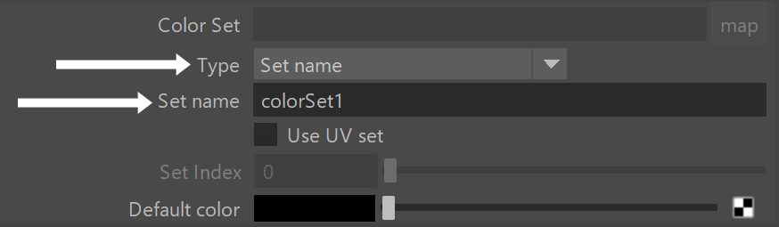
When using a V-Ray Vertex Colors texture as a color map for the RGB slot, or a mask to modulate any of the emission channels (e.g. Discharge, Smoke, etc.), make sure to set the Type to Set name and the Set name to colorSet1. colorSet1 is the default naming convention for Maya's vertex color sets. If you add additional color sets (using Mesh Display → Create Empty Set), each consecutive set will be named colorSet2, colorSet3, etc.
For a step by step tutorial on using the Vertex Color texture for as the Source's RGB map, please check the Simulation RGB Workflows (Chapter 3) tutorial.
Otherwise, if you want to use a Vertex Color texture in the Discharge Mask, Temperature Mask, Smoke Mask, Fuel Mask or Particle Mask, note that it will read the Vertex Alpha and not the Vertex Color RGB. If you are using vertex painting, make sure to paint in RGBA mode and use Alpha = 0 for areas that should not emit. When using the Vertex Color texture as a mask, its Vertex Color RGB does not matter at all.
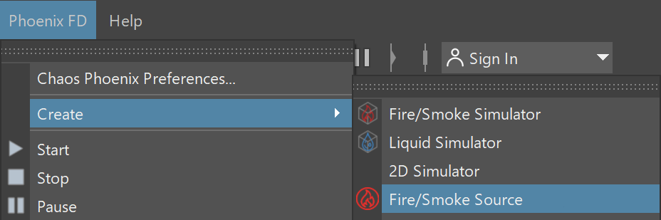
UI Paths: ||Phoenix FD menu|| > Create > Fire/Smoke Source
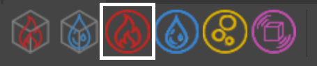
||Phoenix FD Shelf|| > Create Phoenix FD Fire/Smoke Source button
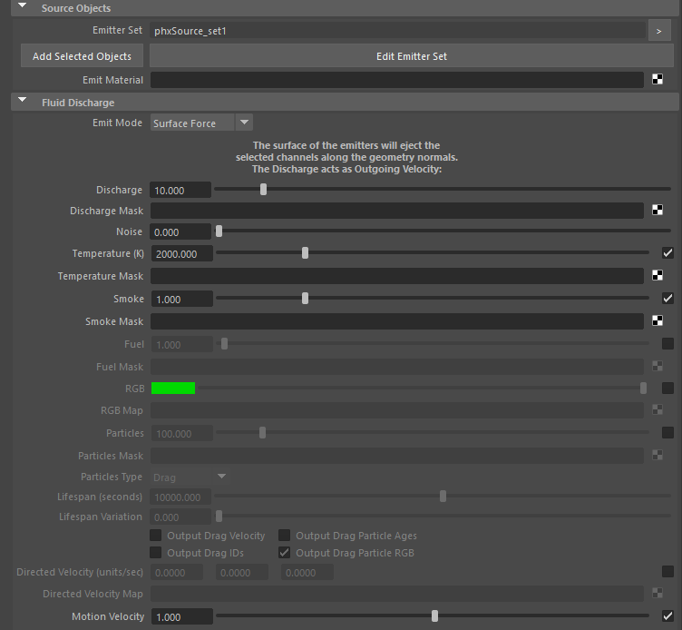
Parameters
Fluid can be emitted from a geometry’s surface, or from the entire volume of an emitting geometry. Non-Phoenix particles, such as nParticles, can also act as emitters for a Phoenix Source. They can emit from a spherical 3D shape, or from instanced geometry.
Note that if the Emit Mode is set to Volume Brush or Volume Inject, and you have a Mask that uses Projection, then the Mask will be applied on the whole volume, based on the closest geometry surface.
Note that the Source icon itself does not emit fluid, so the position of the icon's viewport gizmo in the scene does not matter.
Instead, you must pick the geometry and/or particles that you want to use as emitters, in the Source’s list.
Emitter Set | nodeSet – Specifies a list of objects that will emit fluid. Both geometry and particle systems can be selected here. Note that if you want to emit from an Instancer, you must select the instanced geometry in this set. Also note that you can add Simulators as emitters as well, as if the surface or the volume of their fluid was a regular geometry in the scene. This way you can use one Simulator to emit fluid into a second Simulator, so you can get effects such as burning liquid. For additional information, please head over to the Interactions Between Simulators page.
Emit Material | material – In Maya objects can have different materials assigned to different polygons of the object. Only polygons with the specified material will emit the fluid.
Emit Mode | ifNotSolid (enum: 0 - 3) – Specifies the way the objects in the Emitter Set emit fluid.
Surface Force – The surface of the emitters will eject the selected fluid channels along the geometry normals. In this mode, the Discharge acts as Outgoing Velocity and it specifies the speed of the emitted fluid in units/sec. The displayed units will change accordingly if the scene units change.
This mode can work with both Solid and non-Solid emitters. If you use a Mask for the discharge in Surface Force mode, white areas of the emitter's surface will eject fast fluid, while darker ones would emit more slowly. Black areas will not emit at all.
Volume Brush – The fluid inside the volume of the emitters will gradually change towards the selected channel values. When this mode is selected, the Discharge acts as Brush Effect (%) and it specifies the rate at which the transition takes place. When Brush Effect is 100%, the fluid will immediately reach the selected channel values, and if Brush Effect is less, it specifies how close the fluid values will get to the values from the Source over 1 second. E.g. if the Temperature inside an emitter's volume is 1000 and the Source emits Temperature 2000 with Brush Effect of 80%, then after 1 second the temperature will have risen to 1800. Note that the Volume Brush mode can both increase or decrease the fluid values, for example if the Smoke in the Source is set to 0.5, the Source would increase the smoke in voxels that have 0.0 smoke until it reaches 0.5, but will decrease the smoke in voxels having 1.0 smoke, again - until it reaches 0.5. This mode is useful for creating standing volumes of fluid with a high Brush Effect, or alternatively - to slowly convert the fluid inside the volume of the emitters to the values selected below over a period of time. Note that you can both increase or decrease the values of the fluid channels in Volume Brush mode. When Brush Effect (%) is 0, then the Source has no effect.
This mode requires that all selected emitters are set into non-Solid mode from their Per-Node Properties. If you use a Mask for the discharge in Volume Brush mode, white zones in the volume will have the Brush Effect you have specified, while darker zones will use a smaller Brush Effect. Completely back zones in the mask would not be affected at all by this Source.
Volume Inject – The volume of the emitters will discharge the selected fluid channels with added pressure. When this mode is selected, the Discharge acts as Inject Power and it specifies the added volume of the injected fluid per second. This mode is useful for getting explosive discharge. Inject Power can be negative, in which case the Source will suck in and delete the fluid.
This mode requires that all selected emitters are set into non-Solid mode from their Per-Node Properties. If you use a Mask for the discharge in Volume Inject mode, white zones in the volume will have the Inject Power you have specified, while darker zones will use a smaller Inject Power. Completely back zones in the mask would not be affected at all by this Source.
Transfer – The volume of the emitters will transfer content from other Phoenix Simulator object(s) into this one. The Discharge acts as Transfer Effect (%).
When emitting from particles in any of the 'Sphere' Particle Shape modes, the Surface Force Emit Mode is not supported - Phoenix will automatically fall back to Volume Inject mode. Only Use Particle Shape supports all 3 emit modes.
Emit Mode: Transfer is not supported by particles either - Phoenix will automatically fall back to using Volume Brush.
Discharge | discharge – This parameter controls the strength of the source. Check Emit Mode for more info.
Discharge Mask | dischargeMult – Allows you to vary the Discharge over the surface or the volume of the emitters. White areas of this map will have the strongest discharge, while black areas of the map will not discharge at all. The individual fluid channels can also be modulated using dedicated maps from the options below. See the info on the Emit Mode option above for more info on how the Mask affects each mode. Make sure to enable the texture's Alpha is Luminance option. For more information on texture mapping in Phoenix, please check the Texture mapping, moving textures with fire/smoke/liquid, and TexUVW page.
Noise | noise – Varies the Discharge across the surface or the volume of the emitting geometry or particle. The variation also changes over time. This is a shorthand for using an animated noise in the Mask slot.
Temperature (K) | useTemperature, temperature – Specifies the temperature of the emitted fluid, in Kelvin. A value of 0 is absolute zero, and a value of 300 denotes room temperature. Temperature above 300 makes the fluid rise up, while temperature below 300 makes it fall down. You can find out more about Phoenix Grid Channel Ranges here.
Temperature Mask | temperatureMult – Allows you to vary the channel over the surface or the volume of the emitters. If this is not used, the Source will emit equal temperature over the entire surface or volume of the emitters. Make sure to enable the texture's Alpha is Luminance option. For more information on texture mapping in Phoenix, please check the Texture mapping, moving textures with fire/smoke/liquid, and TexUVW page.
Smoke | useSmoke, smoke – Specifies the density of the emitted Smoke. This value is usually between 0 and 1, but it can be set greater than 1 if you wish your smoke to look thick and heavy even after traveling some distance. You can find out more about Phoenix Grid Channel Ranges here. If the Smoke channel is not enabled in the Output rollout of the Simulator, this parameter will be ignored.
Smoke Mask | smokeMult – Allows you to vary the channel over the surface or the volume of the emitters. If this is not used, the Source will emit equal smoke density over the entire surface or volume of the emitters. Make sure to enable the texture's Alpha is Luminance option. For more information on texture mapping in Phoenix, please check the Texture mapping, moving textures with fire/smoke/liquid, and TexUVW page.
Fuel | useFuel, fuel – Specifies the amount of emitted Fuel. If the Fuel channel is not enabled in the Output rollout of the Simulator, this parameter will be ignored.
Fuel Mask | fuelMult – Allows you to vary the channel over the surface or the volume of the emitters. If this is not used, the Source will emit the same amount of Fuel over the entire surface or volume of the emitters. Make sure to enable the texture's Alpha is Luminance option. For more information on texture mapping in Phoenix, please check the Texture mapping, moving textures with fire/smoke/liquid, and TexUVW page.
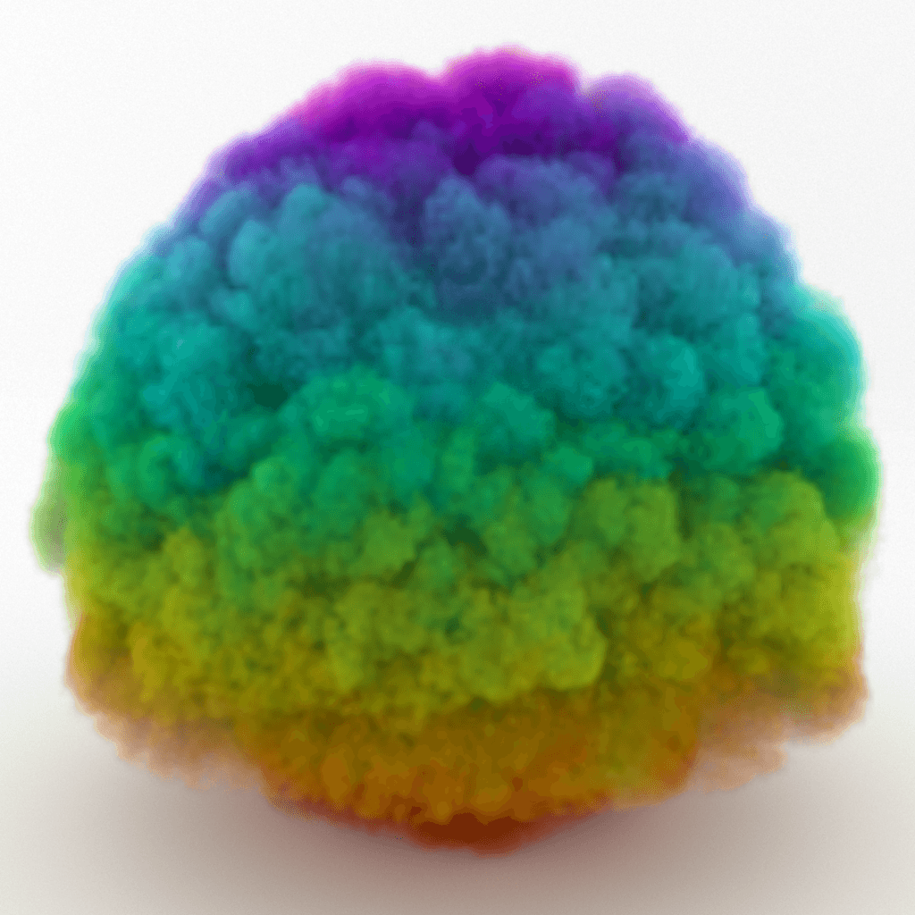
RGB | useUvw, uvw – If the RGB Map is not enabled, the emitted fluid's RGB channel will contain the specified color. If the RGB Map is enabled, the RGB values from the texture map will be used instead of the color swatch. If the RGB channel is not enabled in the Output rollout of the Simulator, this parameter will be ignored. Also, note that if Emit Mode is set to Volume Brush or Volume Inject and the Map uses Projection, then the Map will be applied on the whole volume, based on the closest geometry surface.
RGB Map | uvwMult – Allows you to vary the RGB over the surface or the volume of the emitters. If this is used, the color swatch is ignored. Otherwise, the Source will emit equal RGB over the entire surface or volume of the emitters. For more information on texture mapping in Phoenix, please check the Texture mapping, moving textures with fire/smoke/liquid, and TexUVW page.
To render the Smoke with these RGB values, set the Smoke Color Based On parameter to RGB. For rendering of liquids, set a Grid Texture as the Diffuse map for a V-Ray Material, and set the Grid texture's Channel to RGB.
Particles | useParticles, particles – Allows the source to emit particles into the Simulator. The particle birth rate is in thousands of particles per second.
Particles Mask | particlesMult – Allows you to vary the amount of particles over the surface or the volume of the emitters. If this is not used, the Source will emit equal amount of particles over the entire surface or volume of the emitters. Make sure to enable the texture's Alpha is Luminance option.
Particles Type | particlesType (enum: 0 - 2) – Specifies the type of particles created by this source:
Drag – The source will emit Drag particles. These are the simplest Phoenix particles and are just carried by the velocity of the simulation, without interacting with one another. They can be shaded using the Particle Shader and can be used for simulation of embers, or integration effects such as dust or sand. The RGB color of Drag particles is inherited from the Source and written in the cache files if the Simulator → Output → RGB Grid Channel is enabled.
Foam – The source will emit Foam particles. Note that Foam simulation must be enabled from the Liquid Simulator so this type of particles can be emitted into it.
Splashes – The source will emit Splash particles. Note that Splash simulation must be enabled from the Liquid Simulator so this type of particles can be emitted into it.
Lifespan (seconds) | particlesLifespan – The maximum age of the particles created by this source, specified in seconds.
Lifespan Variation | particlesLifespanRandom – Adds variation of the particles' lifespan, specified in seconds.
Drag particles are created as separate particle systems per each Source that creates them, using the name of the emitting geometry. This is why the particle channels written to the simulation cache files are chosen from the Source, unlike the channels of other particle types which are set through a Simulator's Output rollout.
Note that writing more channels to the cache files takes more time and will add up to the simulation time, so if you know in advance that you will not be needing a certain channel for rendering, then it would help the simulation times if you turn it off.
Even if you do not simulate visible fluid like smoke or fire, there can still be Velocity simulated within the grid, if for example, you animate an object to move around inside the grid to stir the Velocity channel. The simulated velocity can then affect Drag particles, and can also be previewed in the viewport, or even rendered.
Output Drag Velocity | particlesOutVel – When enabled and the Particles Type is set to Drag, this parameter exports the Velocity channel to the cache files, so that you can use it for rendering with motion blur or coloring of particles based on their speed using the Particle Texture.
Output Drag IDs | particlesOutIDs – When enabled and the Particles Type is set to Drag, this parameter exports the ID channel to the cache files.
Export Drag Particle Ages | particlesOutAges – When enabled and the Particles Type is set to Drag, this parameter exports the Age channel to the cache files.
Export Drag Particle RGB | particlesOutRGB – When enabled and the Particles Type is set to Drag, this parameter exports the RGB channel to the cache files.
The RGB Grid Channel output under Simulator → Output has to be enabled for the RGB simulation to take place.
Direct Velocity (units/sec) | useDirectedVelocity – Creates velocities in a certain direction or based on a Map.
Direct Velocity Map | directedVelocityMap – Allows you to vary the Direct Velocity over the surface or the volume of the emitters. If this is not used, the Source will emit equal Direct Velocity over the entire surface or volume of the emitters. When using Map, the Direct Velocity is generated from the selected texture and is not multiplied by the value added in the Directed Velocity X/Y/Z slots.
When using a Texture map to direct the Velocity of the fluid emitted from the Source:
The Red color affects the Direct Velocity on the +/- X axis.
The Green color affects the Direct Velocity on the +/- Y axis.
The Blue color affects the Direct Velocity on the +/- Z axis.
Motion Velocity | useVelocity, velocity – When enabled, moving emitters will affect the velocity of the fluid and make it follow the emitter. This effect is controlled with the specified multiplier. If the emitter is not moving, this option has no effect.
- Particles with attached geometry will act like standard geometry obstacles and will push the fluid by default, as long as their Solid Phoenix property is enabled.
- Particles without geometry will need to be attached to a Source in order to interact with the fluid in any way.
- Particles without geometry can emit fluid using their shape and size using the Source's Particle Shape and Custom Prt Size options.
- Particles without geometry will not affect the fluid's motion by default, so you need to enable Motion Velocity explicitly if you need this effect.
- If Motion Velocity is enabled, the fluid emitted by a particle may refuse to leave the particle shape area and continue to move together with the particle, because it will have the same velocity.
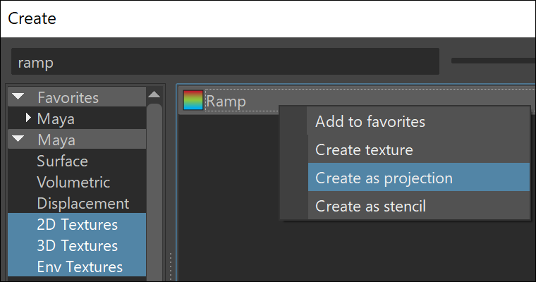
When using 2D Textures (such as Ramp for example) together with a Phoenix Source in Volume Brush mode you will need to set up a Projection and adjust the 3D placement node in order to get correct mapping.
While creating the texture, right-click over the Menu item in the Create panel and choose "Create as projection". Then select the projection node, press on the Interactive placement button and adjust your placement node.
TexUVW Emission
The main purpose of the Texture UVW feature is to provide dynamic UVW coordinates for texture mapping that follow the simulation. If such simulated texture coordinates are not present for mapping, textures assigned to your simulation will appear static, with the simulated content moving through the image. This undesired behavior is often referred to as 'texture swimming'. In Phoenix such textures can be used for mapping the fire or smoke color and opacity of volumetrics, as well as the color and opacity of meshes. Texture can be also used for displacing volumetrics and meshes.
UVW coordinates are generated by simulating an additional Texture UVW Grid Channel which has to be enabled under the Output rollout for the settings below to have any effect.
For additional information on the Texture UVW feature, please check the Texture mapping, moving textures with fire/smoke/liquid, and TexUVW page.
Inherit TexUVW From Geom | texUVWFromGeom – Sets the UVW Grid Channel value for each cell where fluid is emitted to the UV value of the emission geometry in that cell. As a consequence, for example, modulating the Smoke Color with a texture on the very first frame will produce a render that looks very close to the original geometry, if the same texture was applied to it. When this option is disabled, the TexUVW values will be based on the position of the emission object inside the Simulator. Please check the Texture UVW example below.
Variation | texUVWVarMode – Variation is used to offset the UVW coordinates upon emission to avoid visible tiling once a texture is applied to the resulting simulation. Similarly to a printer, if the UVW channel is not varied, it would be like printing out the same sentence over and over again on each new line. When varied, the printer will change the line being printed. The following methods are available:
- No Variation - The emitted TexUVW will not change over time.
- Along U/V/W - The emitted TexUVW value will change over time in the U/V/W direction and by the amount set in Variation/Sec.
- Along Grid/Object/World Normals - The emitted TexUVW value will change over time in the direction of the emitting geometry's normals in Grid/Object/World space and by the amount set in Variation/Sec. Grid space is the system of the Simulator, it always has the Z axis pointing up. Object space is the local transform of the emitter.
Variation/Sec | texUVWVarSpeed – Controls the variation speed - the default value of 1 will cause textures assigned for rendering to repeat exactly once for every 30 frames (1 second) of the simulation.
Emission from Particles
Time Base | timeBase (enum: 0 - 1) – This parameter is used when emitting from particle systems. It allows you to animate the parameters using the age of the particle instead of the timeline frame time.
Absolute – Parameters of the source will be animated based on the timeline frame time.
Particle Age – Parameters of the source will be animated based on the age of the particle. This way, values at timeline frame 0 will apply to each particle at the moment of its birth, and e.g. values at frame 10 will apply to the particle 10 frames after it was born. This allows particles born at different moments to perform identical animations offset in time. This can be useful e.g. if you want all particles to emit strongly after they are born and reduce their emission after a while, but in case the particles are born through a long period of time, the Absolute mode will change the discharge of all particles together, while Particle Age will allow each particle to have its own copy of the animation.
Time Scale different than 1 will affect the Particle Age in the Fire Source. In order to get predictable results you will have to adjust the keyframes using this formula: Time Scale * Time in frames.
Particle Shape | partShapeType (enum: 0, 1, 3) – This parameter is used when emitting from particle systems.
Sphere, 1 voxel – Each particle will be the size of one grid cell. Particle sizes and shapes will be ignored.
Sphere, use size – The particle sizes (radiusPP) will be used.
Sphere, custom size – The particle shape will be spherical and the size will be taken from the Custom Particle Size field.
When a source emits from non-solid particles in any of the Sphere modes, the simulator traces each moving sphere and emits continuously throughout its trajectory, no matter how fast the particle is moving and how many steps the simulation uses. In a contrary way, in Use particle shape mode, the particles are getting evaluated the same way as regular mesh geometries, so in motion they are sampled only at the simulation steps without filling the trajectory in between the particle positions in time. In such case, if a particle moves very quickly and the simulator has low Steps per Frame, the trajectory of the particle would get interrupted and you should increase the simulation steps in order to keep it continuous.
Custom Particle Size | partCustSize – Specify a custom size for the particles using this option. The size is in scene units.
Discharge Modifiers
A list of modifiers that allow modulating the emission using properties of the source object (such as Normal, Position or Speed) at the point of interaction with the simulator. A ramp control is used to remap from the value of the specified property to a user-specified multiplier.
See the Discharge Modifiers page for more information.
Example: RGB Map Vertex Color
 Smoke Simulation
Map = Vertex Color
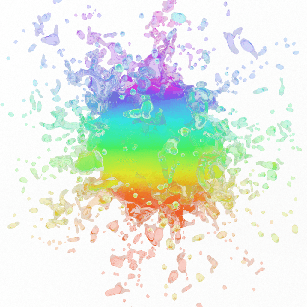 Liquid Simulation
Map = Vertex Color