This page provides a tutorial on the different workflows available for controlling the RGB Grid Channel of the Phoenix Simulator in Maya.
Overview
This is an Entry Level tutorial which requires no previous knowledge of Phoenix. A basic understanding of Maya would be helpful but is not a prerequisite for being able to follow along.
Requires Phoenix FD 3.12.00 for V-Ray Next and V-Ray Next for Maya Hotfix 1 Official Release for Maya 2015 or newer. You can download official Phoenix and V-Ray from https://download.chaos.com. If you notice a major difference between the results shown here and the behavior of your setup, please reach us using the Support Form.
The instructions on this page guide you through the different workflows available for controlling the RGB Grid Channel of the Phoenix Simulator in Maya.
The tutorial is divided in chapters covering different topics such as:
- Using a Phoenix Source to emit a uniform RGB color.
- Using a Phoenix Source to emit RGB from a texture.
- Using a Phoenix Source to emit RGB from the vertex colors of the source geometry.
- Using a Phoenix Source in Brush mode to change the RGB color of Simulations while the simulation is running.
- Using a Phoenix Mapper in conjunction with a V-Ray Distance Texture to change the RGB based on the proximity of an object in the scene while the simulation is running.
All these workflows are suitable for both Fire/Smoke and Liquid simulations.
The Download button below provides you with an archive containing example scenes based on the instructions on this page.

Units Setup
Scale is crucial for the behavior of any simulation. The real-world size of the Simulator in units is important for the simulation dynamics. Large-scale simulations appear to move more slowly, while mid-to-small scale simulations have lots of vigorous movement. When you create your Simulator, you must check the Grid rollout where the real-world extents of the Simulator are shown. If the size of the Simulator in the scene cannot be changed, you can cheat the solver into working as if the scale is larger or smaller by changing the Scene Scale option in the Grid rollout.
Go to Windows → Settings and Preferences → Preferences → Settings and set the Working Units to centimeters.
Set the Time to 30fps. We do this to ensure the setup is identical to the Simulation RGB Workflows tutorial for 3ds Max. You may skip this step if you find it unnecessary. Keep in mind the final result of your simulation may turn out slightly different.

Chapter 1: Emitting uniform RGB color from the Phoenix Source
Create the following nodes:
- Create → Polygon Primitives → Sphere with a Radius of 5 cm. Move it 5 units up in the Y direction so it sits at the origin.
- Phoenix Simulator with a Grid→ Cell Size (units) of 1.0 and Grid → X / Y / Z Size of 40 / 60 / 40.
- Phoenix Fire/Smoke Source.
Middle-Mouse button drag the Sphere to the automatically generated emission set (phxSource_set1) of the Source so it knows to use it as an emission geometry.

Start the simulation from the Phoenix Simulator → Action Buttons.
Open the Phoenix Simulator → Preview rollout and Enable GPU Preview. Note the presence of Fire in addition to the Smoke.
Because we are trying to focus on shading the Smoke Color based on the RGB Grid Channel, in the next step we will disable the export of the Temperature Grid Channel and also the rendering of Fire from the Volumetric Shader.

Open the Phoenix Simulator → Rendering rollout.
From the Rendering → Fire sub-rollout, set the Based on to Disabled. This will disable the emissive component of the Volumetric Shader. The Fire should no longer be visible in the GPU Preview as well.
Open the Rendering → Smoke Color sub-rollout and set the Based on option to RGB. The color of the smoke in the Viewport should go black. There are 2 reasons for this:
- When setting the Based on option to a certain channel, you need to make sure that the specified channel is cached to disk. This is done from the Output rollout → Output Grid Channels.
- The default RGB color of the Phoenix Simulator is black (0, 0, 0). You need to set the color to another value either from the Phoenix Source, or by using a Phoenix Mapper. We take a look at the Mapper workflow in Chapter 5.

You can think of the Rendering → Fire/Smoke sub-rollouts as the Phoenix Volumetric Shader. Those rollouts hold the majority of the parameters that govern how the supported Grid Channels (such as Smoke, Temperature, RGB, Velocity, etc.) are used during the rendering stage.
The Volumetric Shader is separated in 3 major sections:
- The Fire and Fire Lights rollouts control the emissive component of the shader. You can specify what channel is used to emit light, how strong is the emission, what color it is and how it affects the Alpha. If you want to learn more on this topic, you can check the Documentation.
- The Smoke Color rollout controls the shading of the volume. You can directly set a uniform Constant Color, use a Texture or a simulated Grid Channel - such as RGB. Importantly, the Smoke Color rollout also holds the settings that govern how the volume is affected by external light sources and by it's own emissive component (the Fire).
- The Smoke Opacity rollout is used to specify where the volume is visible inside the Phoenix Simulator. While most of the time you'll use either the Simple Smoke, or the Smoke options, it's also possible to set this to Speed, for instance, and tweak the Opacity Diagram below such that "smoke" is visible only in those areas of the container where the Velocity Grid Channel is above a certain threshold.
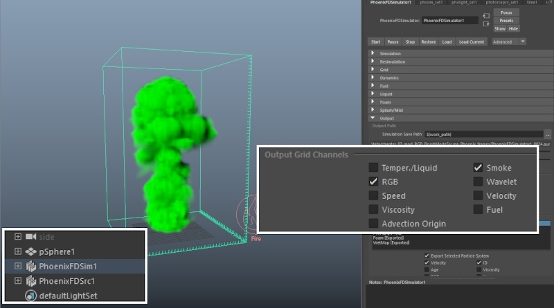
Go to the Phoenix Simulator → Output rollout and disable Temperature from the Output Grid Channels section.
Enable the RGB. You need the RGB Grid Channel stored to disk if you want to use it for the Smoke Color. This holds true in general - if you want to use a certain Grid Channel in the Volumetric Shader, you need to cache it to disk during the simulation stage.
The Output rollout controls which Grid Channels are saved in the .aur or .vdb cache files on your hard drive. Any time you run a simulation, Phoenix stores those files in the background.
Since we are not utilizing the Temperature grid channel for this tutorial, saving it to disk is unnecessary.

Finally, select the Phoenix Source and enable RGB. The color swatch to the right (green by default) is used to specify what color is emitted into the RGB channel from the source geometry (the Sphere).
If you run the simulation, the Smoke should now be green.
Note that the emission with this setup is uniform. You can have 3 different spheres with 3 separate Phoenix Sources whose RGB emission is set to a different color. In the next chapter we see how to use a single Phoenix Source to emit different colors all from the same geometry.
Hit Phoenix Simulator → Start. The color of the smoke in the viewport should now be green.

To recap:
- Create a source geometry, a Phoenix Simulator and a Phoenix Source.
- Add your source geometry to Emission Set of the Phoenix Source.
- Enable GPU Preview on the Phoenix Simulator.
- Open the Rendering rollout of the Simulator.
- Disable Fire and set the Smoke Color Based on to RGB so the Smoke color is based on the RGB Grid Channel.
- Enable the export of RGB channel from the Output rollout and disable Temperature to save some disk space.
- Set the desired emission color on the Phoenix Source. Don't forget to enable RGB from the tickbox.

Chapter 2: Emitting RGB from a texture
We will continue with the scene from Chapter 1. You can use the chapter_01_emitting_uniform_RGB_from_phoenixSource.ma file if you didn't follow along.
Assuming that you already have a setup with a working Smoke Color by RGB, we will simply assign a new Lambert material to the Sphere and plug a Checker texture to the diffuse slot.
You may want to use the Trash icon on the Phoenix Toolbar to delete the cache files if the Viewport preview is getting in the way.
If you can't see the colors of the noise texture in your Viewport, hit the '6' button with the mouse cursor over the Viewport to enable the texture preview.
Assigning a material to the source geometry is not a requirement for the texture emission to work. We do this so we can easily preview the texture in the Viewport.

Phoenix will take into account the tweaks made to the placement nodes for your texture.
Both the 2D and the 3D placement nodes are supported.

Once you're happy with the Checker texture's appearance, connect it to the RGB Map Input swatch on the Phoenix Source. You can do this either by Middle-Mouse button dragging it from the Hypershade window to the RGB Map slot, or by manually typing the name.
The Source is now aware of the texture and will use it for the emission of RGB.

Hit Phoenix Simulator → Simulation → Start to run the sim.
The color of the Smoke should now be based on the texture you applied to the Source. This holds true for all textures, not just the Checker. For example, you could manually paint a texture in Photoshop and use that in the source.
Chapter 3: Emitting RGB based on the Vertex Color of the Source Geometry
Continuing with the scene from Chapter 2, delete the cache files or hide the Phoenix Simulator so it doesn't get in the way.
We will quickly go over painting vertex color on our source geometry using the Mesh Display → Paint Vertex Color Tool.
Before we start, select the emission geometry and assign the default lamber1 material. This step is necessary so you can preview the painted vertex colors.

With the emission geometry selected, go to Mesh Display → Paint Vertex Color Tool.
Feel free to paint any colors you wish.
If you ever accidentally close the Tool Settings Window, you can invoke it again by double-clicking on its icon in the Toolbox to the left.

Select the Phoenix Source and assign a V-Ray Vertex Colors texture to the RGB map parameter.
Set the Type to Set name, and the Set name to colorSet1.
colorSet1 is the default naming convention for Maya's vertex color sets. If you add additional color sets (using Mesh Display → Create Empty Set), each consecutive set will be named colorSet2, colorSet3, etc.
Hit the Simulator→ Start button to run the simulation. The RGB emission should now be based on the colors you painted on the Sphere.

Chapter 4: Changing the RGB color of simulations after emission with a second Phoenix Source in Brush mode
Chapters 1-3 covered the basics - how to set up the export, preview and rendering of the RGB channel, and how to emit into the RGB channel from a piece of geometry using the Phoenix Fire/Smoke Source.
In this chapter and the next, we go over 2 separate workflows which allow you to modify the RGB channel after emission. We will first take a look at the simpler of the two - using a Phoenix Source in Brush Mode.
To start off, re-create the setup from Chapter 1, or open the provided project file called chapter_01_emitting_uniform_RGB_from_phoenixSource.ma.
- Create a source geometry, a Phoenix Simulator and a Phoenix Source.
- Add your source geometry to the Emitter Nodes list of the Phoenix Source.
- Enable GPU Preview on the Phoenix Simulator.
- Open the Volumetric Option from the Rendering rollout of the Simulator.
- Disable Fire and set the Smoke Color Based on to RGB so the Smoke color is based on the RGB Grid Channel.
- Enable the export of RGB channel from the Output rollout and disable Temperature to save some disk space.
- Set the desired emission color on the Phoenix Source. Don't forget to enable RGB from the tickbox.
Set the RGB on the Source to mid-gray (RGB on the Fire Source is green by default).
Also, rename the Source to phx_source_smoke or something along those lines. In the next step we add a second one so keeping organized will be quite helpful.
As the Smoke comes out of the Sphere, its color should now be gray because we set the RGB on the source as such. What if we could somehow change the color once the smoke reaches a certain area of the simulator, or touches a certain object? For that to happen, you need to find a way to modify the RGB channel.
Remember - the Smoke does not magically carry the color by itself - there is an entirely separate RGB Grid Channel being simulated and the color of the smoke is being based on it. If you set the RGB Channel for the entire bounding box of the simulator to 3 separate colors, the Smoke will happily travel through and inherit them.

Create another Phoenix Fire/Smoke Source and rename it to phx_source_rgb to keep your scene tidy.
Then, create a box and position it somewhere along the path of the smoke. We will set the box as the Emitter object for the phx_source_rgb Phoenix Source and only emit RGB from it.
As a result, when the smoke moves through the volume of the box, it will inherit whatever color we've specified on the RGB swatch of phx_source_rgb.

Add the box to the emission set of phx_source_rgb and set the Emit Mode to Volume Brush. You will be prompted with a message stating that only Non-Solid emitters can be used in Brush Mode and Phoenix can covert the object to Non-Solid for you - choose Yes.
Disable Temperature and Smoke and enable RGB for phx_source_rgb.
Set the Discharge to 100.
If you now Start the simulation, the smoke should be gray and only turn green once it passes through the box.
You can control how fast the transition happens from the Discharge parameter on the source. At 100, the color will change immediately while a lower value will produce a slower transition over time.
The Volume Brush and Volume Inject modes use the entire volume of the specified emitter objects, as opposed to the Surface Force Mode which emits only from the outer surface (basically, the shell) of the object.
Furthermore, if the box is Solid the smoke will collide with it instead of passing right through which is not what we want.
As a side note - you can bring up the Phoenix FD Properties for any object in your scene with the Right Mouse Button.

The methods discussed in Chapters 2 can be applied here as well - you can modify the RGB emission of phx_source_rgb with a texture map. Try it out!
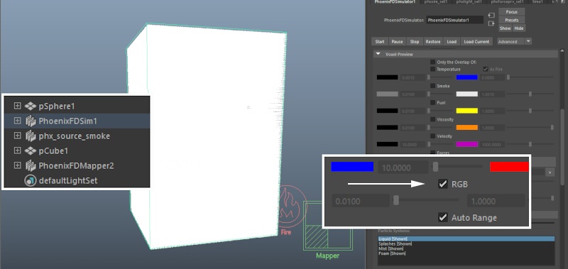
Instead of using the Smoke channel as the middle-man, you can preview the RGB Channel directly. To do so, go to Simulator → Preview rollout → GPU Shade Preview sub-rollout → disable GPU Preview.
Then, in the Voxel Preview section, enable RGB at the bottom and disable all the other channels.
You should now be able to see the values in the RGB channel even before the Smoke comes into contact with it.
The voxel preview can be quite useful for debugging your setup.

Chapter 5: Changing the RGB color of Fire/Smoke and Liquid simulations after emission with a Mapper and a V-Ray Distance Texture
In this final chapter, we will re-create the setup from Chapter 4 using a Phoenix Mapper and a V-Ray Distance Texture.
The Distance Texture will be used as a Mask for the Mapper which will constrain the Mapper to setting the values of the RGB Channel only in proximity of the object specified in the Distance Texture Objects list.
As this setup can be a bit harder to wrap your head around, here's a detailed explanation:
- The V-Ray Distance Texture has 4 parameters to pay close attention to: the Objects list, Far Color, Near Color and Distance. When you apply the texture to object A, it returns a color value between Near Color and Far Color based on the distance between object A and the objects in the Objects list. This is done for each shading point of the object A - the texture will calculate the distance between the shading point and the objects in the list and return a certain value.
- The Phoenix Mapper is used to set the values for each individual cell/voxel of the Simulator. This is an important distinction - it doesn't simply flood the entire container - you can specify where (Mask) the value (Map) is applied.
- You can think of the Phoenix Mapper as an object that you're applying the Distance Texture to. Instead of shading points, we now work with the cells/voxels of the Simulator. The texture will return a value based on the distance between each individual voxel and the geometry objects in the list.
- The result of this can be used as a Mask to feed to the Mapper. You can then give it a Map and its color will only be applied to those voxels where the Distance Texture evaluates to a value greater than 0 (black).

Starting with the final scene from Chapter 3, delete the phx_source_rgb but keep the box geometry.
Go to Phoenix FD → Create → Mapper and create one in your scene. The position of the Mapper in your scene does not matter - you can place it anywhere you see fit.
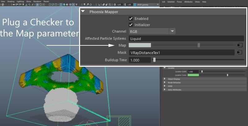
Set the Channel parameter to RGB so the Mapper knows to affect the RGB Channel of the Simulator.
The Affected Particle Systems parameter defaults to Liquid and can be used to specify what Particle Systems will be affected by the Mapper in the case that you are simulating Liquids.
As we are creating a Fire/Smoke Simulation, this parameter will have no effect.
If you're running a Liquid simulation and you want to affect the color of the particles, add the respective particle system name to the Affected Particle Systems list (ie. Liquid, Foam, Splash etc.).

Open the Hypershade and create a V-Ray Distance Texture.
Add pCube1 (or any other object that you'd like to serve as a mask for the Mapper's Influence) to the to the Objects set of the Distance texture (named distTexSet1 by default). The easiest way to add an object to a Maya set is to Middle-Mouse button click and drag in the Outliner.
Leave everything else at default for the time being.

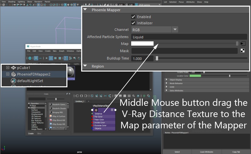
Select the Phoenix Mapper node and Middle-Mouse-Button click and drag the V-Ray Distance Texture to the Map parameter on the Mapper.
Earlier we mentioned that we will use the Distance Texture as a Mask so you may be wondering why are we putting it into the Map slot instead. It's just for preview - the Map parameter is what is actually set so it's easier to plug the texture here, set it up correctly and then move it to the Mask slot.
Open the Preview rollout of the Phoenix Simulator and disable GPU Preview.
Enable Voxel Preview → RGB and disable Smoke, Temperature, etc. if those are enabled.
The voxel preview will allow you to easily check how the Mapper is affecting the RGB Channel.
Go to the Simulation rollout and uncheck Use Timeline Stop Frame. Set Custom Stop Frame to 2 so the simulation will only run for one frame.
Hit Start.
The entire RGB Channel should now be white.
Instead, we want only the voxels near the object to be white and the rest of them - black. That way, when we put the Distance Texture in the Mask slot, it will only affect the voxels close to the object.
The reason for this is the settings of the V-Ray Distance Texture. By default, the Far Color is set to white (therefore the RGB of the voxels far away from the object is set to white), and the Near Color is black (so the RGB of the voxels close to the object is set to black).
Reverse the Far and Near Color - set the Far Color to black and the Near Color to white.
Hit Start.
You should now see an area around the box transitioning from white to black. The thickness of this 'wrapper' around your object is controlled by the Distance parameter on the V-Ray Distance Texture.
Set the Distance to 3.

The 'wrapper' should now fit tightly around your object. That's all you need to do for the V-Ray Distance Texture.
Plug the Distance Texture into the Mask slot of the Phoenix Mapper and remove it from the Map slot with Right-Mouse-Button → Break Connection.

Add a Checker to the Map slot (or any other texture - that's up to you).
Increase the Simulation → Stop Frame value to 10 or so and hit Start to run the simulation.
If you're looking at the voxel preview, you will notice that the RGB is correctly set up at the start of the simulation but once the smoke reaches it, it gets diluted and disappears.
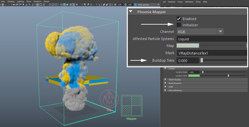
The reason is the Mapper settings. By default, the Initializer option is enabled. This means that the Mapper will set the specified channel (RGB in our case) to whatever value is provided by the Map on the first frame of the simulation and then it will become inactive.
Disable the Initializer option, so the Mapper would affect the entire duration of the simulation.
Lastly, the Buildup Time parameter at the bottom controls how quickly the Mapper will set the affected cells of the simulator to the specified Map value. Buildup Time is in seconds - the default value of 1 means that the Mapper will gradually set the RGB channel for the affected voxels over 1 second.
Set Buildup Time to 0 so the effect is instantaneous. If you want the colors to mix on contact instead of being outright overwritten, setting this to 0.1 or so should be a good starting point.
That is all. You can hit Start to run the simulation.