This page provides information on the Interaction rollout.
Overview
It's strongly recommended to avoid geometry that has cavities inside. These may cause jets and other undesired phenomena.
This roll-out is used to enable/disable the interaction with objects in the scene. There are several different types of objects that may affect the simulation: Sources, Solid objects, Forces, etc.
By default, all these scene elements will interact with the simulator unless otherwise specified by the Interaction Set. If you want to disable the interaction you have to put the objects in the Interaction set. If there are more objects that don't need to interact with the simulator, you may alternatively switch to the Include list mode by un-checking Exclude List. In this mode you have to add to the Interaction Set all the objects that you want to interact with the Simulator.
Since all forces affect the simulation by default, adding a force in your scene to be used by e.g. nParticles will automatically affect your simulation and this might not be desired. You may use the Interaction Set to exclude a force if you wish so.
UI Path: ||Select PhoenixFDSim|| > Attribute Editor > Scene Interaction rollout
Parameters

Interaction Set | interactionSet – Specifies a set that defines a list of objects to include/exclude from the simulation. All other objects in the scene are excluded/included respectively.
Exclude List | interExcludeList – When enabled, the Interaction Set defines which objects to exclude (and all other objects are included). When disabled, it specifies which objects to include (and all other objects are excluded).
Exclude Hidden Objects | interExcludeHidden – When enabled, the hidden objects will be excluded regardless of the Interaction Set content. Templated objects (using Display Layers in the Channel Box or Drawing Overrides on the Shape node) are also considered hidden.
Ignore Render Layers – When enabled, the render layers will be ignored during the simulation. Otherwise, the simulator will interact only with objects in the current layer.
Geometry

Object voxels | objectVoxels – Phoenix FD is a grid-based simulator, and geometry is converted into voxel form. The cells overlapped by a solid geometry object are frozen and processed in a different way. When a given voxel is half-way inside the geometry, this option helps you choose whether this voxel is going to be frozen or not. It does not produce significant change in the simulation, but is of crucial importance for the rendering. For example, if the object voxels are circumscribed, the liquids can't reach the real object's surface and this is visible in the rendering. You can override this option per object from the Phoenix FD Object Properties extra attribute. For more information, see the Object Voxels example below.
Circumscribed – All voxels that intersect the surface are considered solid. This is recommended for fire simulations.
Center – The surface voxels are considered solid only if their bigger part lies in the object
Inscribed – All voxels that have intersection with the surface are considered non-solid. It's recommended for liquid simulations.
The Object voxels setting is a simulation option. If its value changes, the simulation must be calculated again for the changes to take effect.
Object Velocity | objectVelocity – Controls how to calculate the motion of the solid objects inside the simulator.
Transformation Only – The movement will be calculated only using the transformation of the object as a whole.
Per Vertex – Along with the global transformation, a per vertex velocity will be also calculated. Note that the count and the order of the vertices must not change during the simulation.
Motion Vector Color Set – Along with the global transformation, Phoenix will add the velocities from the color set defined in the "Motion Vector Color Set" attribute of the mesh.
Use Viewport Subdivision – When enabled, the viewport subdivision will be used for simulation.
Example: Object Voxels
The example below shows the difference in emission when the object uses Inscribed (voxels intersecting the surface are non-solid therefore do not emit) vs Circumscribed (voxels intersecting the surface are solid) voxelization.
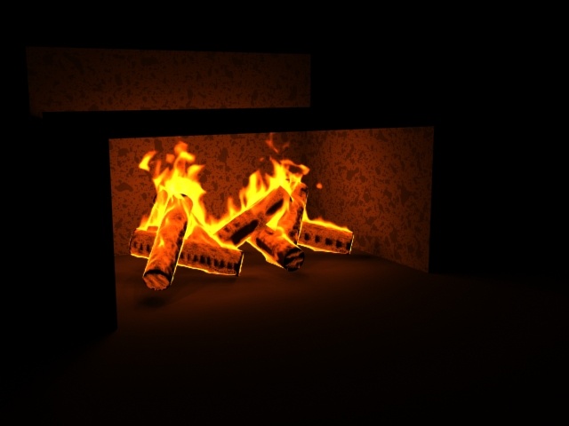
Object voxels = Inscribed
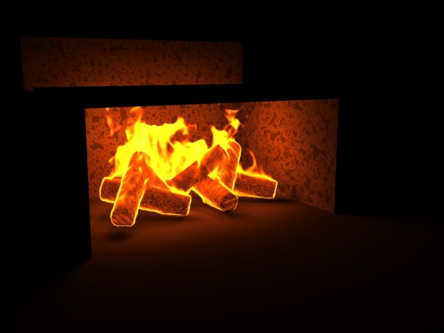
Object voxels = Circumscribed