This page provides information on the V-Ray Spot Light.
Overview
The V-Ray Spot Light is a V-Ray specific light source that can be used to create a physically accurate light that directs a narrow beam of light with falloff.
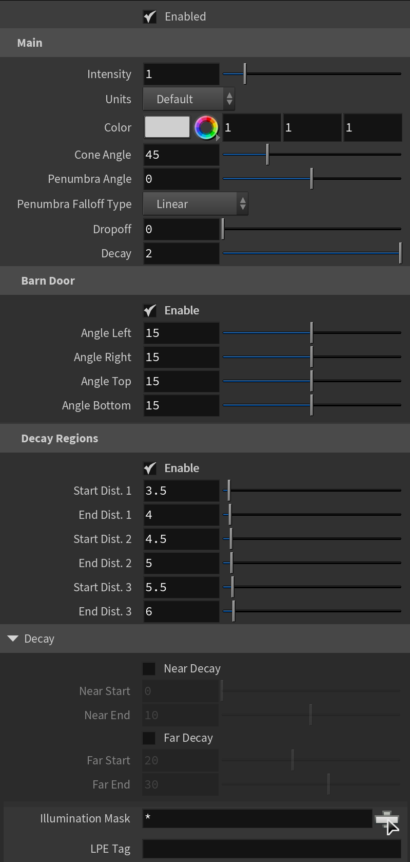
Main
Enabled – Turns the light on and off.
Intensity – Multiplier for the light strength; this is also the light intensity in the units set by the Units parameter.
Units – Specifies the light units. Using correct units is essential when using the V-Ray Physical Camera. The light automatically takes the scene's unit scale into consideration to produce the correct result for the scale you are working with. The possible values are:
Default – The color and multiplier directly determine the visible color of the light without any conversion. The light surface appears with the given color in the final image when seen directly by the camera (assuming there is no color mapping involved).
Lumens – Total emitted visible light power measured in lumens. When this setting is used, the intensity of the light does not depend on its size. A typical 100W electric bulb emits about 1500 lumens of light.
Lm/m/m/sr – Visible light surface power measured in lumens per square meter per steradian. When this setting is used, the intensity of the light depends on its size.
Watts – Total emitted visible light power measured in watts. When this setting is used, the intensity of the light does not depend on its size. Keep in mind that this is not the same as the electric power consumed by a light bulb for example. A typical 100W light bulb only emits between 2 and 3 watts as visible light.
W/m/m/sr – Visible light surface power measured in watts per square meter per steradian. When this setting is used, the intensity of the light depends on its size.
Color – Specifies the color of the Spot Light.
Cone Angle – Specifies the angle of the light cone formed by the V-Ray Spot Light. See the Cone Angle example below for illustration.
Penumbra Angle – Specifies the angle within the light cone at which the light begins to transition from full strength to no lighting. When set to 0, there is no transition and the light produces a harsh edge. For illustration, see the Penumbra Angle example below.
Penumbra Falloff Type – Determines how the light transitions from full strength to no lighting inside the light cone.
Linear – The light does not have any falloff.
Smooth Cubic – The light fades in a realistic way, similar to the Inverse Square option for Decay.
Dropoff – Controls the dropoff rate of the light intensity.
Decay – Controls the behavior of the light intensity from the distance of the light source.
Barn Door – Enables or disables the barn door effect. Barn doors restrict the light cone on the four sides of the light to produce a rectangular light shape. In the real world, barn doors are four planes attached in a square around the light.
Decay Regions – Enables decay regions to be used with the V-Ray Spot Light.
Near Decay – Toggles near decay on and off. See the examples below for more information.
Near Start – Determines where the fade in starts. Anything before this point is rendered dark.
Near End – Determines where the fade in ends. After this threshold, the light is at its full value.
Far Decay – Toggles far decay on and off. See the examples below for more information.
Far Start – Determines where the fade off starts.
Far End – Determines where the light reaches a value of 0, i.e. completely fades off.
Illumination Mask – Specifies which objects to be affected by the V-Ray Spot light.
LPE Tag – Allows you to specify a string tag that can be used in a Light Path Expression to isolate the contribution from this light. See the Advanced Light Path Expressions page for more information.
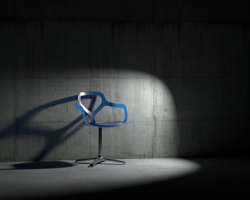
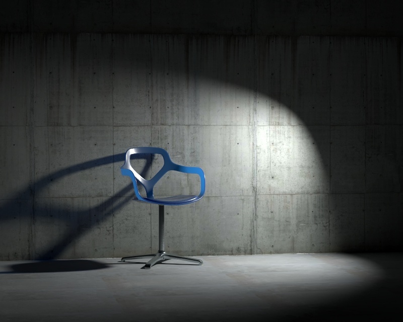
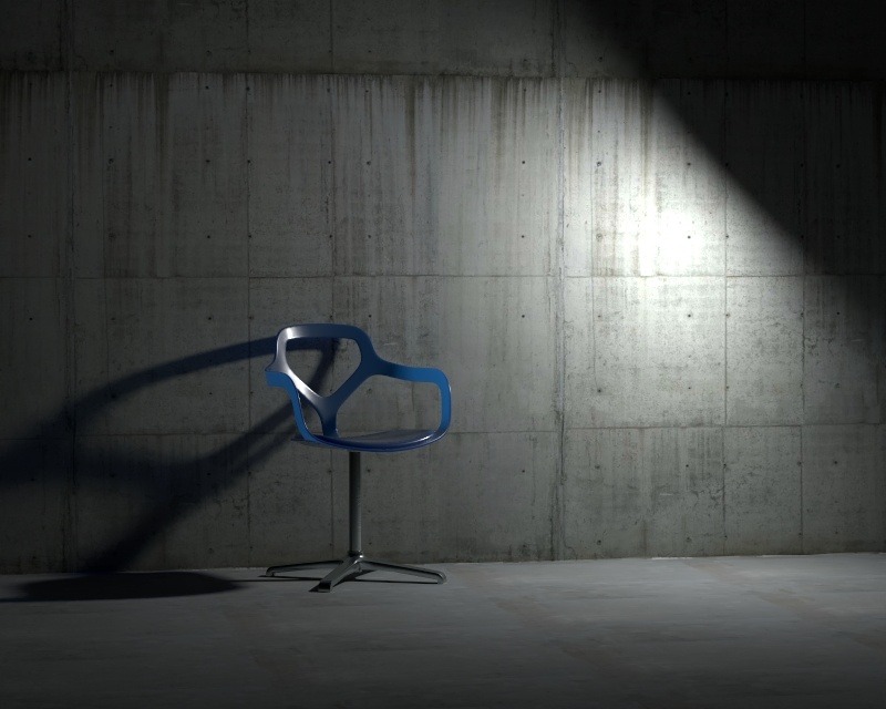
Example: Cone Angle
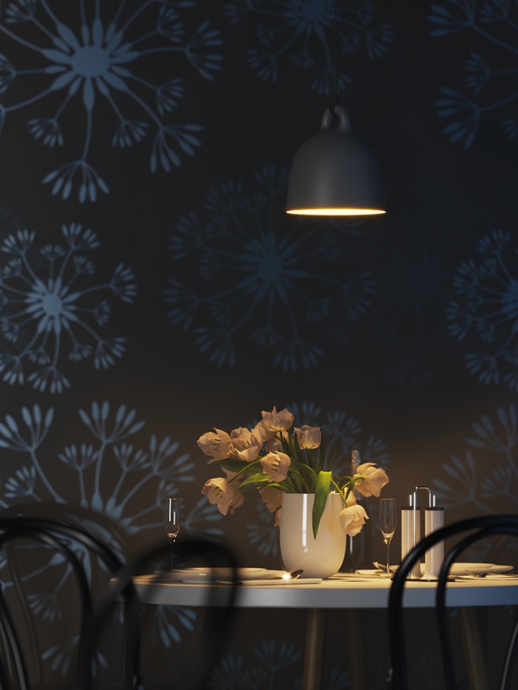
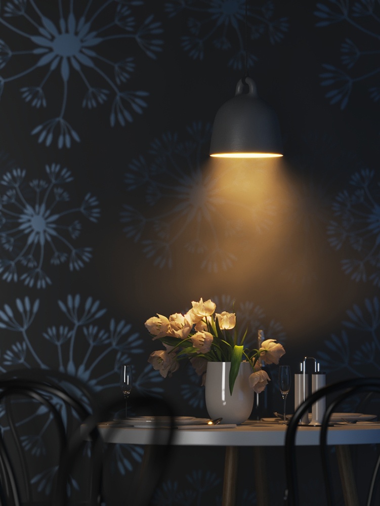
This example demonstrates how the light changes with the change of the Cone Angle. The Penumbra Angle is set to 20 for all renders, only the degrees of the Cone Angle change. Notice how lower degrees result in sharp shadows and focused light, while higher degrees make the light diffused and the shadows blurrier.
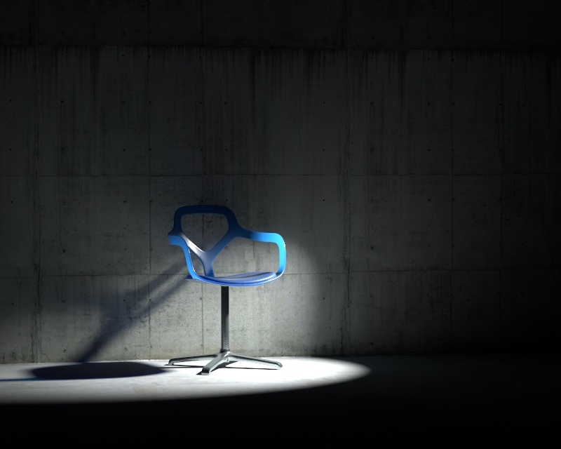
Cone Angle = 10 degrees

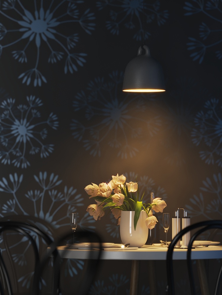
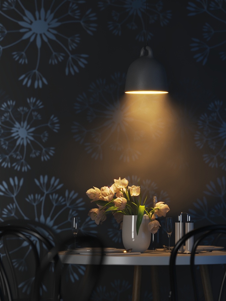
Cone Angle = 30 degrees
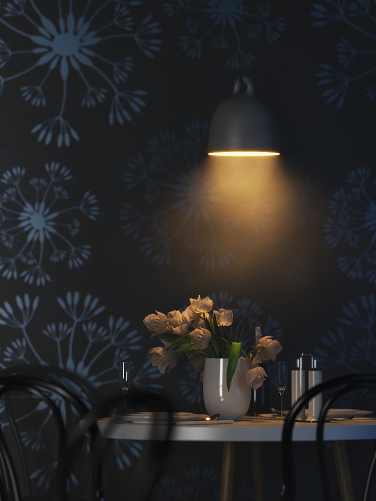
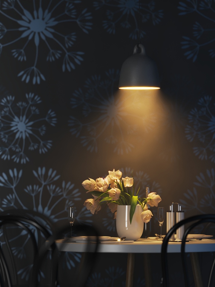
Cone Angle = 45 degrees
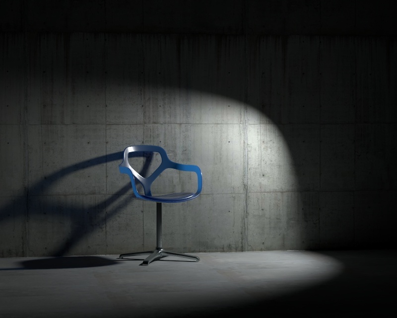
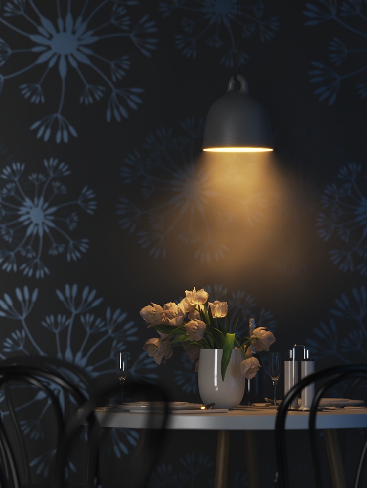
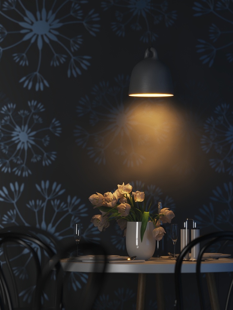
Cone Angle = 60 degrees
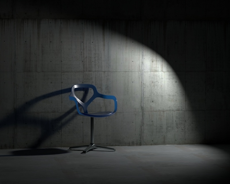
Cone Angle = 90 degrees
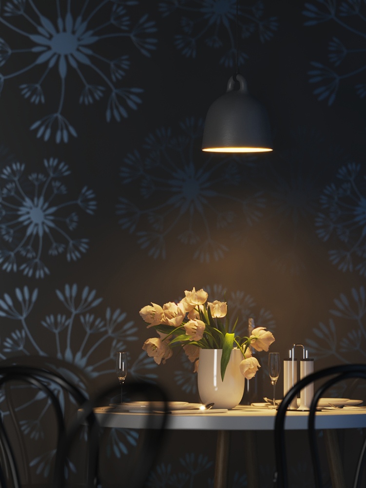
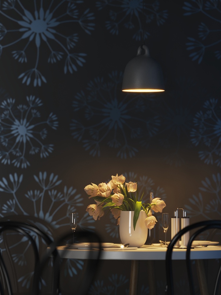
Example: Penumbra Angle
This example demonstrates the behavior of the light when changing the Penumbra Angle. The Cone Angle is set to 20 for all renders.

Penumbra Angle = 0 degrees
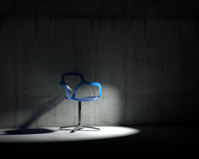
Penumbra Angle = 15 degrees
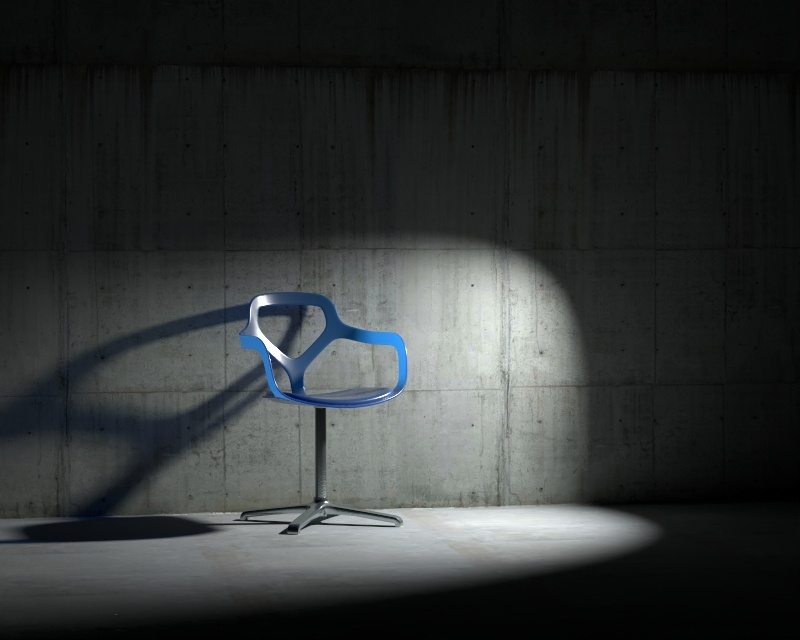
Penumbra Angle = 30 degrees
Penumbra Angle = 45 degrees
Penumbra Angle = 90 degrees
This example shows the variances achieved by changing the Near Start parameters only. Near Start 10, Near End 60 Near Start 30, Near End 60 Near Start 50, Near End 60 This example shows the variances achieved by changing the Near End parameters only. Near Start 0, Near End 10 Near Start 0, Near End 30 Near Start 0, Near End 50 This example shows the variances achieved by changing the Far Start parameters only. Far Start 10, Far End 60 Far Start 30, Far End 60 Far Start 50, Far End 60 This example shows the variances achieved by changing the Far End parameters only. Far Start 60, Far End 60 Far Start 60, Far End 100 Far Start 60, Far End 120 This example shows some artistic lighting results achieved by using both Near and Far decay options. Near Start 0, Near End 15, Far Start 30, Far End 60 Near Start 20, Near End 35, Far Start 40, Far End 55 Near Start 30, Near End 60, Far Start 90, Far End 120
Example: Decay Near Start
Example: Decay Near End


Example: Decay Far Start
Example: Decay Far End

Example: Near and Far Decay


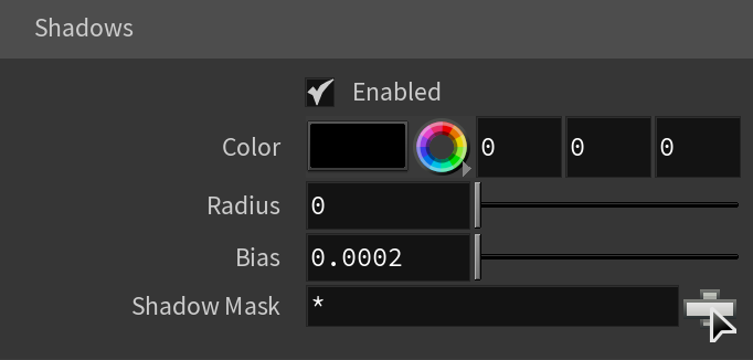
Shadows
Enabled – When enabled, the light casts shadows. Disable this option to turn off shadows for the light.
Color – Controls the color of shadows for this light. Note that anything different from black is not physically correct.
Radius – Specifies the size of the light. A value of 0.0 makes the light a point light. Larger values produce soft (area) shadows.
Bias – Moves the shadow toward or away from the shadow-casting object (or objects). Higher values move the shadow toward the object(s) while lower values move it away. If this value is too extreme, shadows can "leak" through places they shouldn't or "detach" from an object. Other effects from extreme values include moire patterns, out-of-place dark areas on surfaces, and shadows not appearing at all in the rendering.
Shadow Mask – Specifies objects that cast shadows when light is directed at them.
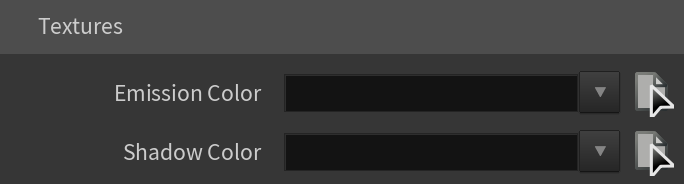
Textures
Emission Color – Specifies the color of the light rays and of the light source itself when visible in renderings.
Shadow Color – Specifies the color of the shadows produced by the light.
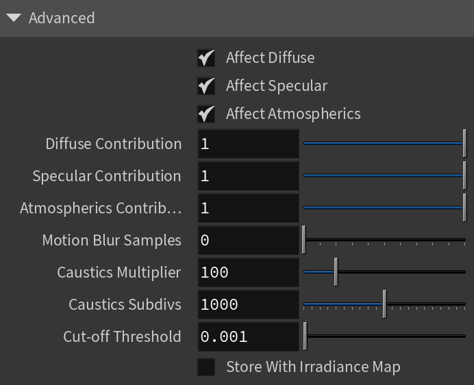
Advanced
Affect Diffuse – Determines whether the light affects the diffuse properties of the materials.
Affect Specular – Determines whether the light affects the specular of the materials. This means glossy reflections.
Affect Atmospherics – Determines whether the light influences the atmospheric effects in the scene.
Diffuse Contribution – When Affect Diffuse is enabled, specifies a multiplier for the effect of the light on the diffuse component.
Specular Contribution – When Affect Specular is enabled, specifies a multiplier for the effect of the light on the specular component.
Atmospheric Contribution – When Affect Atmospherics is enabled, this value determines the amount of involvement.
Motion Blur Samples – Specifies the number of samples used to sample the light for motion blur.
Caustics Multiplier – Specifies a multiplier for the generated caustics by the selected object. Note that this multiplier is cumulative - it does not override the multiplier in the Caustics Tab of the V-Ray Render Settings.
Caustics Subdivs – Only used when calculating Caustics. Lower values mean more noisy results, but render faster. Higher values produce smoother results but take more time.
Cut-off Threshold – Specifies a threshold for the light intensity, below which the light is not computed. This can be useful in scenes with many lights, where you want to limit the effect of the lights to some distance around them. Larger values cut away more of the light; lower values make the light range larger. When this value is 0.0, the light is calculated for all surfaces.
Store With Irradiance Map – When enabled and GI calculation is set to Irradiance map, V-Ray calculates the effects of the V-Ray Spot Light and stores them in the irradiance map. The result is that the irradiance map is computed more slowly but the rendering takes less time. The irradiance map can also be saved for later use.