This page provides information about the V-Ray Object Properties SOP.
Overview
The Object Properties SOP offers different render settings on a per-object basis such as primary and secondary visibility, visibility to camera, displacement, hair properties, matte/shadow properties, etc.
Assigning Object Properties SOP and/or Displacement materials works with packed geometry. It is not expected to work with packed fragments.
For more information on object properties that work with other geometry different than packed geometry, see the following links: Object Properties, Hair Properties, Displacement.
Object Properties
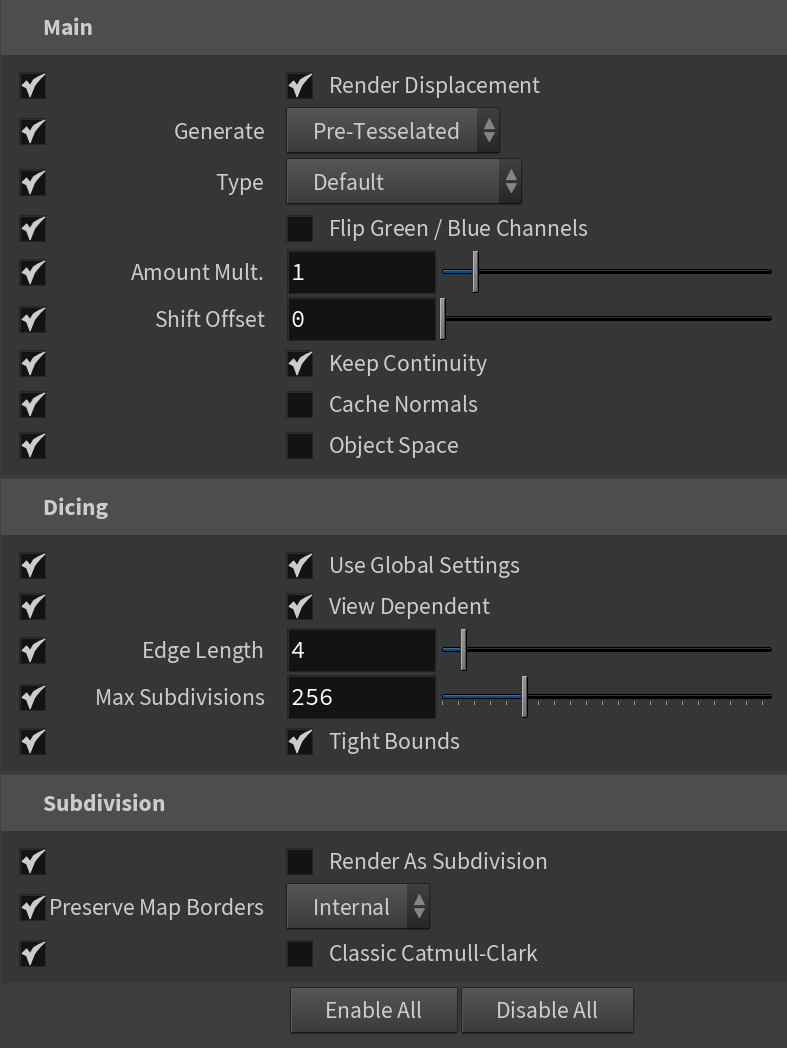
Enable All – Enables all parameters in all Object Properties tabs at once.
Disable All – Disables all parameters in all Object Properties tabs at once.
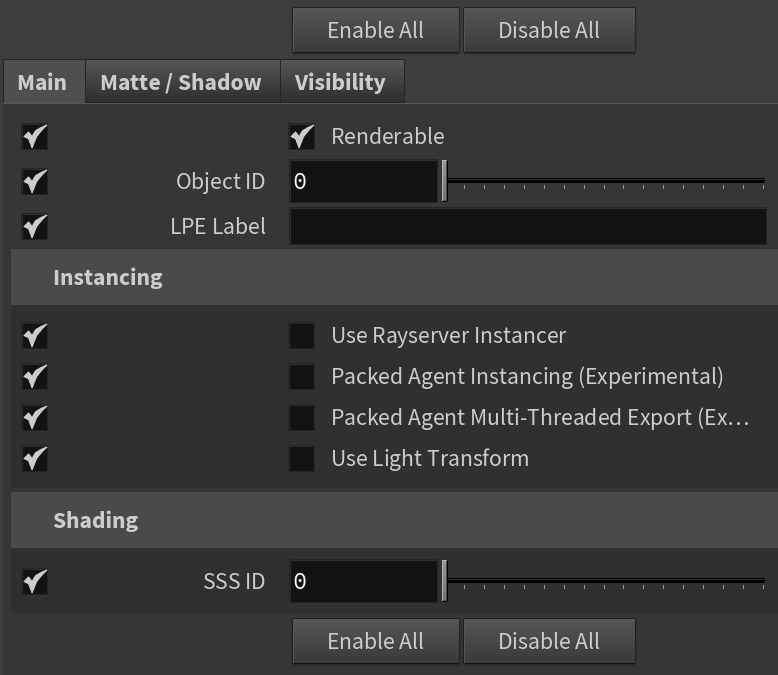
Main
Renderable – When disabled, the instance isn't rendered. The object's properties can still be queried from within VEX but no geometry is rendered. This is roughly equivalent to turning the object into a transform space object.
Object ID – Specifies an ID for the object. This is used by the MultiMatte render element which creates selection masks based on Object IDs.
LPE Label – Specifies a light path expression label for the object. Find more information about what light path expressions are at the Advanced Light Path Expressions page.
Use Rayserver Instancer – Uses the GeomRayserverInstancer node instead of Instancer2 node.
Packed Agent Instancing (Experimental) – Experimental packed agent instances detecting.
Packed Agent Multi-Threaded Export (Experimental) – Experimental multi-threaded packed agent export. Note that this option may take a lot of RAM.
Use Lights Transform – Takes light transform into account for instancing.
SSS ID – Used to tell V-Ray SSS and V-Ray Skin materials that objects with the same ID need to share the same illumination samples when using raytraced multiple scattering. This avoids illumination seams between those objects.
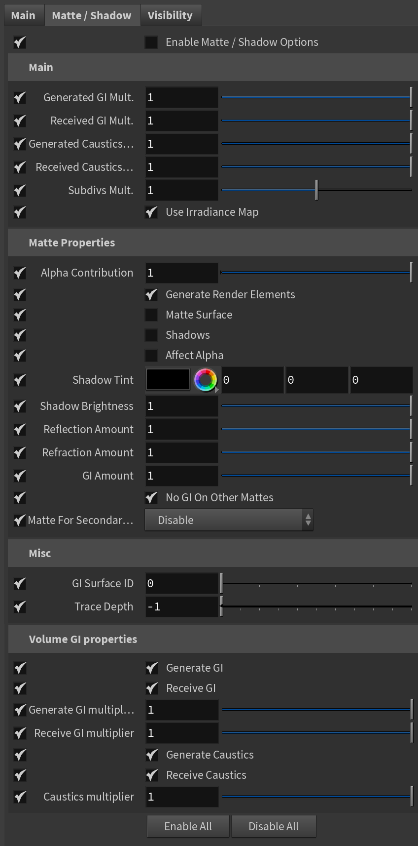
Matte / Shadow
Enable Matte/Shadow Options – Enables the Matter/Shadow options.
Generated GI Mult. – Specifies a multiplier for the amount of GI generated by the material.
Received GI Mult. – Specifies a multiplier for the amount of GI received by the material.
Generated Caustics Mult. – Specifies a multiplier that controls how much caustics the object generates. Note that in order to generate caustics, an object must have a reflective or refractive material.
Received Caustics Mult. – Specifies a multiplier that controls how much caustics the object receives. When light is refracted by objects that generate caustics, the resulting caustics are only visible when they are projected on caustics receivers.
Subdivs Mult. – Specifies a multiplier for the subdivisions of all secondary ray tracing done for the particular surface.
Use Irradiance Map – When enabled, the irradiance map is used to approximate diffuse indirect illumination for the object. If disabled, brute force GI is used. You can use this for objects in the scene which have small details and are not approximated very well by the irradiance map.
Alpha Contribution – Determines the appearance of the object in the alpha channel of the rendered image. A value of 1.0 means the alpha channel is derived from the transparency of the base material. A value of 0.0 means the object does not appear in the alpha channel at all and shows the alpha of the objects behind it. A value of -1.0 means that the transparency of the base material cuts out from the alpha of the objects behind. Matte objects are typically given an alpha contribution of -1.0. Note that this option is independent of the Matte surface option (i.e. a surface can have an alpha contribution of -1.0 without being a matte surface).
Generate Render Elements – When enabled, V-Ray generates zDepth, velocity, extra tex, and multi matte render element for matte objects. When this check box is disabled V-Ray does not generate any render elements for matte objects.
Matte Surface – Makes the material appear as a matte material, which shows the background instead of the base material when viewed directly. Note that the base material is still used for things like GI, caustics, reflections, etc.
Shadows – Makes shadow visible on the matte surface.
Affect Alpha – Makes shadows affect the alpha contribution of the matte surface. Areas in perfect shadow produce white alpha, while completely unoccluded areas produce black alpha.
Shadow Tint – Specifies an optional tint for the shadows on the matte surface.
Shadow Brightness – An optional brightness parameter for the shadows on the matte surface. A value of 0.0 makes the shadows completely invisible, while a value of 1.0 shows the full shadows.
Reflection Amount – Shows the reflections from the base material.
Refraction Amount – Shows the refractions from the base material.
GI Amount – Determines the amount of GI shadows.
No GI On Other Mattes – Causes the object to appear as a matte object in reflections, refractions, GI, etc. for other matte objects. Note that if this is on, refractions for the matte object might not be calculated (the object appears a matte object to itself and is not able to "see" the refractions on the other side).
Matte For Secondary... – Normally the base material is used when an object with a MtlWrapper is seen through reflections/refractions. This option controls whether the MtlWrapper shows the base material or environment when seen through secondary rays (e.g. reflections/refractions).
Disable – The base material is used when the MtlWrapper is seen through reflections/refractions.
Without Projection Mapping – The environment is seen through reflections/refractions.
With Projection Mapping – The environment is seen through reflections/refractions with projection mapping to increase the realism.
GI Surface ID – This number can be used to prevent the blending of Light Cache samples across different surfaces. If two objects have different GI surface IDs, the light cache samples of the two objects are not blended. This can be useful for preventing light leaks between objects of vastly different illumination.
Trace Depth – Specifies the number of times a ray can be reflected. Scenes with lots of reflective and refractive surfaces may require higher values to look correct. A value of -1 specifies this option is controlled by the global Render Settings.
Generate GI – Controls whether the object generates indirect illumination. Note that to obtain the caustics effect you must set the appropriate value for the Caustics multiplier below as well as put some objects that generate caustics in the scene.
Receive GI – Controls whether the object receives indirect illumination. A multiplier can be specified for the received indirect illumination.
Generate GI multiplier – A multiplier for the amount GI generated by the material.
Receive GI multiplier – A multiplier for the amount GI received by the material.
Generate Caustics – When enabled, the selected objects refract the light coming from light sources that are caustics generators, so that caustics are produced. Note that in order to generate caustics, an object must have a reflective or refractive material.
Receive Caustics – When enabled, the selected objects become caustic receivers. When light is refracted by objects that generate caustics the resulting caustics are only visible when they are projected on caustics receivers.
Caustics multiplier – A multiplier for the caustics.
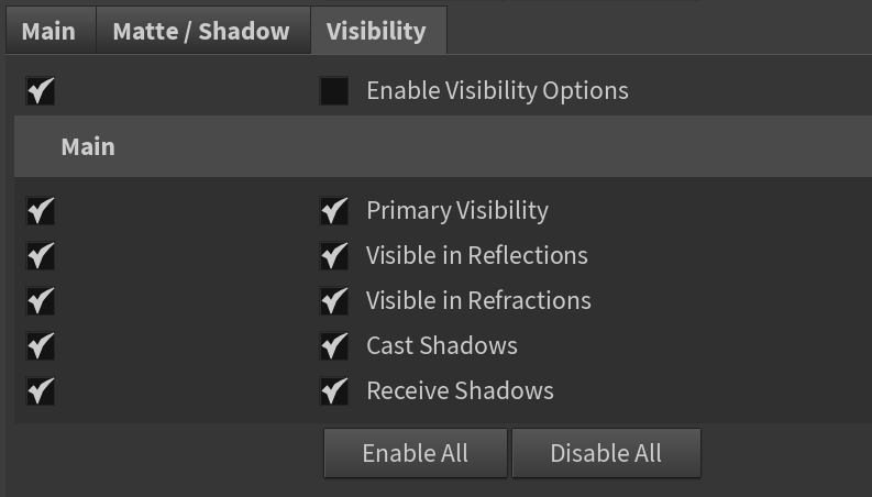
Visibility
Enable Visibility Options – Enables the Visibility Options.
Primary Visibility – When disabled, the object appears perfectly transparent to camera rays.
Visible in Reflections – When disabled, the object appears perfectly transparent to reflection rays.
Visible in Refractions – When disabled, the object appears perfectly transparent to refraction rays.
Cast Shadows – When disabled, the object is invisible to shadow rays from lights and does not cast shadows. Note that when disabled, the object doesn't affect the GI.
Receive Shadows – When disabled, the object does not receive shadows.
Subdivision
Main
Render Displacement – Turns on/off displacement effect.
Generate – Specifies how the resulting triangles of the displacement algorithm are inserted into the rayserver.
On the Fly – Dynamic
Pre-Tesselated – Static (default)
Type – Specifies the mode in which the displacement is rendered.
Default – Takes the original surface geometry and subdivides its triangles into smaller sub-triangles which are then displaced. It can be applied for arbitrary displacement maps with any kind of mapping.
2D – Bases the displacement on a texture map that is known in advance. The displaced surface is rendered as a warped height-field based on that texture map. The actual raytracing of the displaced surface is done in texture space, and the result is mapped back into 3D space. The advantage of this method is that it preserves all the details in the displacement map. However, it requires that the object have valid texture coordinates. You cannot use this method for 3D procedural textures or other textures that use object or world coordinates. The displacement map can take any values.
Vector – If using a displacement texture that is not grayscale, V-Ray converts it to grayscale before rendering the displaced geometry. This mode allows V-Ray to use the Red, Green, and Blue channels of the displacement texture to displace the geometry in the U and V directions in addition to the direction of the face normal.
Vector (Absolute) – A vector-type displacement mode in which the texture is interpreted as 0.5-based tangent space displacement map.
Vector (Object) – Only meaningful when a V-Ray Ptex is used for displacement, where the texture values represent 0-based displacement in object space. If mesh information is stored in the Ptex file, V-Ray can also displace correctly mesh deformations.
Flip Green / Blue Channels – When enabled, the Green and Blue channels of the supplied texture map are swapped.
Amount Multiplier – The amount of displacement for white areas of the displacement map. If Use Global Settings is enabled, this value is multiplied by the global displacement Amount option. A value of 0.0 means the object appears unchanged. Higher values produce a greater displacement effect. This can also be negative, in which case the displacement pushes geometry inside the object.
Shift Offset – Specifies a constant which is added to the displacement map values, effectively shifting the displaced surface up and down along the normals. This can be either positive or negative.
Keep Continuity – When enabled, V-Ray tries to produce a connected surface. Use it when you get splits (usually around sharp edges) in the displaced geometry.
Cache Normals – When enabled, V-Ray generates and saves information about the normal of each newly generated vertex. This requires additional memory but speeds up the shading calculations during rendering. Please see the Displacement rollout of the Options Tab to improve output result.
Object Space – When enabled, the parent transformation affects the amount of displacement. Use this option for 3D displacement.
Dicing
Use Global Settings – When enabled, the global Displacement quality settings from the V-Ray Renderer are used.
View Dependent – Determines if view-dependent tessellation is used. When enabled, Edge Length determines the maximum length of a subtriangle edge, in pixels. A value of 1.0 means that the longest edge of each subtriangle is about one pixel long when projected on the screen. When View Dependent is off, Edge Length is the maximum subtriangle edge length in world units.
Edge Length – The maximum length of a subtriangle edge after subdivision. This affects the degree of subdivision before displacement, which in turn affects the quality of the displacement itself. Each triangle of the original mesh is subdivided into a number of subtriangles. More subtriangles mean more detail in the displacement, slower rendering times and more memory usage. Less subtriangles mean less detail, faster rendering and less memory used. Units used for this parameter depend on the View Dependent parameter.
Max Subdivisions – Controls the maximum number of subtriangles generated from any one triangle of the original mesh. The square of this value is used. For example, a value of 256 means that at most 256 x 256 = 65536 subtriangles are generated for any given original triangle. It is recommended not to increase this value a great deal over the default value of 256. If you need to use higher values, it is better to first tessellate the original mesh itself into smaller triangles before starting the displacement process.
Tight Bounds – When enabled, initialization is slower but tighter bounds are computed for the displaced triangles making rendering faster.
Subdivision
Render As Subdivision – When enabled, the object is subdivided during rendering.
Preserve Map Borders – Specifies how to handle subdivisions of UV coordinates at UV seams. The possible values are:
None – UVs are always subdivided regardless of whether they are on a UV seam or not;
Internal – Only preserves UVs if they are on an internal UV seam;
All – Does not subdivide UVs on UV seams.
Classic Catmull-Clark – When enabled, V-Ray uses the Classic Catmull-Clark method for subdividing the mesh instead of the hybrid one used by default. This option should be enabled only if the mesh is composed entirely of rectangular faces or it does not work.
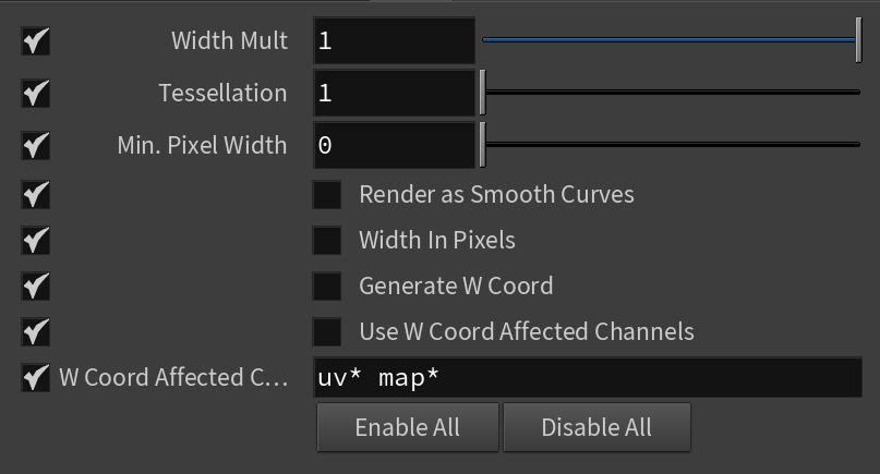
Hair
Width Mult – A hair width multiplier. It is used as base width if a "width" attribute is not found.
Tessellation – Allows manual control over the number of subdivisions when intersecting the spline based hairs.
Min. Pixel Width – Sets the minimum pixel width of each hair strand to help ensure samples are taken consistently between pixels. A value of 0 means no minimum width is applied, but increasing it helps make sure each strand is consistently rendered. This additional calculation increases render times, but smooths the hair width.
Render as Smooth Curves – When enabled, hair strands are represented as splines instead of line segments.
Width In Pixels – When enabled, the Width Mult parameter is calculated in pixels.
Generate W Coord – When enabled, V-Ray generates a W mapping coordinate that represents the position of the shaded point along the hair strand. This is useful for mapping a ramp texture, for example.
Use W Coord Affected Channels – When enabled, V-Ray generates a W mapping coordinate only for channels in the W Cord Affected Channels list.
W Coord Affected Channels – А list of space-separated channels that are affected when generating a W mapping coordinate.