This page provides information on V-Ray Photometric Lights, also known as IES Lights.
Overview
Photometric lights utilize an .ies file which contains the distribution profile for the light. An .ies file contains complete specifications of a real world light bulb or tube including the shape of the light's cone and the steepness of the light's falloff. Such files are usually provided by the manufacturer of the real-world bulb, and the information in those files, gathered through lab experiments, is extremely accurate in its representation of the light source. By loading an .ies file, the light's properties are recreated within Houdini and used by V-Ray during rendering.
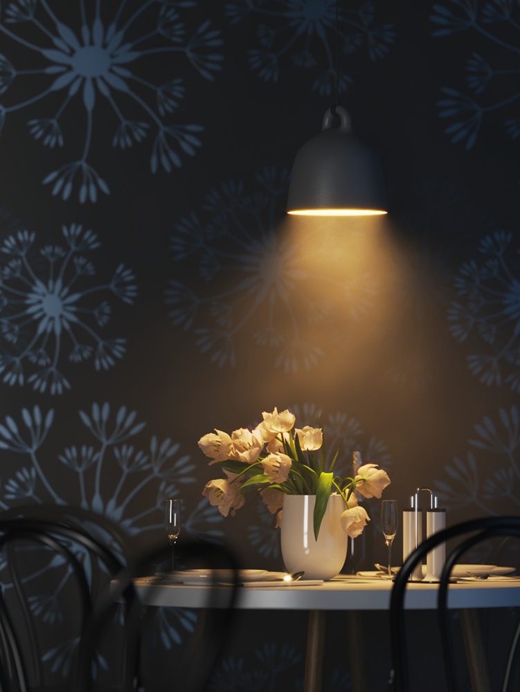
IES lights are particularly useful for architectural interior renderings, where it can be important to show an accurate representation of the use of specific man-made light sources in the scene.
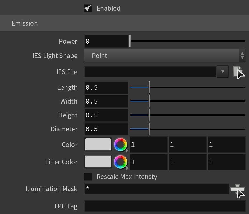
Emission
Enabled – Enables the IES light.
Power – Specifies the intensity of the light in lumens (lm). When a value of 0.0 is used, the default luminous power from the IES profile is used. For illustration, see the Power example below.
IES Light Shape – Determines how the shape of the light specified in the .ies file is taken into consideration during the calculation of shadows.
From File – Uses the shape information stored in the .ies file.
Rectangular
Circular – Treats the light shape as a planar circular area light. Its dimensions can be specified with the diameter parameter below.
Sphere – Treats the light shape as a sphere light. Its dimensions can be specified with the diameter parameter below.
Vertical cylinder
Horizontal Cylinder Oriented Along Luminaire Length
Horizontal Cylinder Oriented Along Luminaire Width
Ellipse Oriented Along Luminaire Length
Ellipse Oriented Along Luminaire Width
Ellipsoid Oriented Along Luminaire Length
Ellipsoid Oriented Along Luminaire Width
Elliptic cylinder
Horizontal Elliptic Cylinder Along Luminaire Length
Horizontal Elliptic Cylinder Along Luminaire Width
Vertical Circle
Vertical Ellipse
Cuboid
IES File – Specifies an .ies file to use for the current light.
Length – Specifies the length for applicable IES Light Shape types.
Width – Specifies the width for applicable Light Shape types.
Height – Specifies the height for applicable Light Shape types.
Diameter – Specifies the diameter for applicable Light Shape types.
Color – Specifies the color of the Photometric Light.
Filter Color – Specifies a color multiplier for the light.
Rescale Max Intensity – When enabled, the intensity values of the IES file are scaled so the new maximum value is set to the New Max Intensity parameter.
New Max Intensity – Specifies the new maximum intensity after rescaling the intensities in the IES file, when Rescale Max Intensity option is enabled. The value is in cd (candela).
Illumination Mask – Specifies which objects to be affected by the V-Ray IES light.
LPE Tag – Allows you to specify a string tag that can be used in a Light Path Expression to isolate the contribution from this light. See the Advanced Light Path Expressions page for more information.
Example: Power
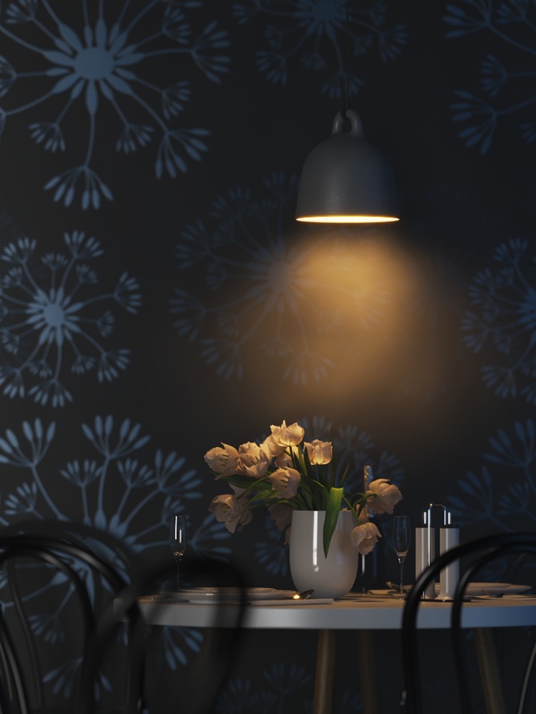
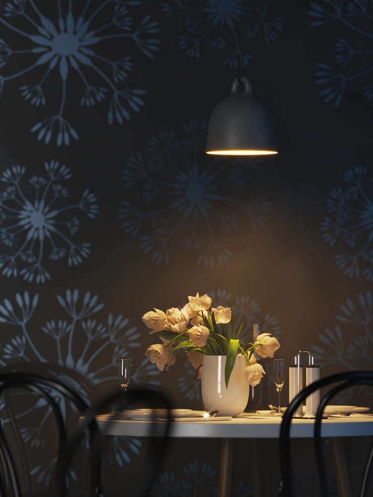
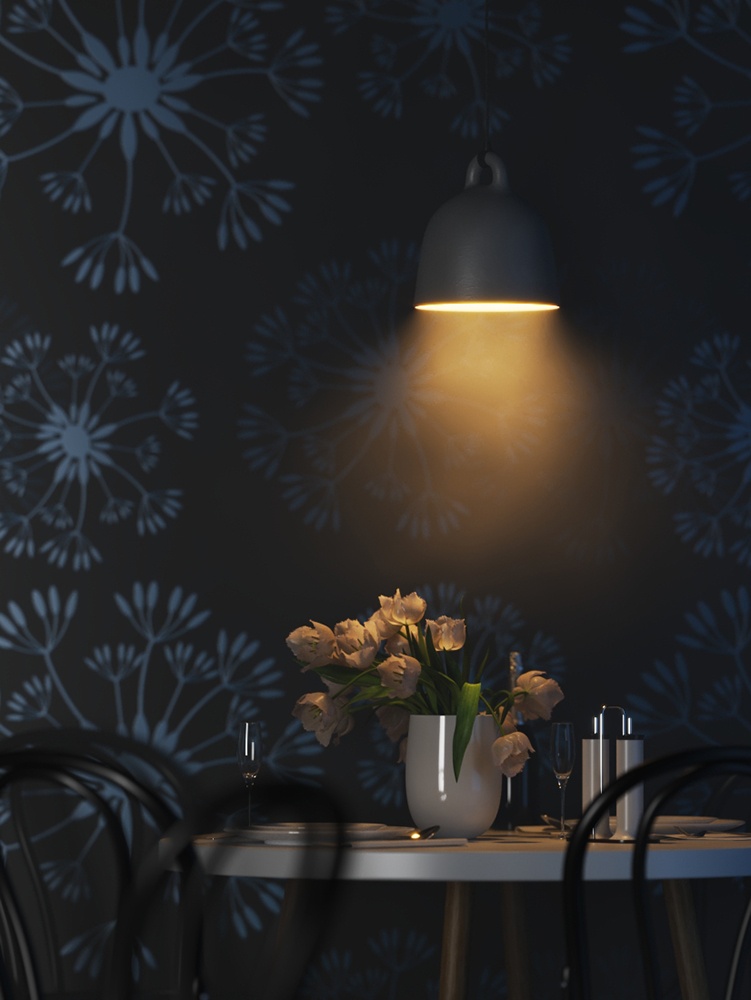
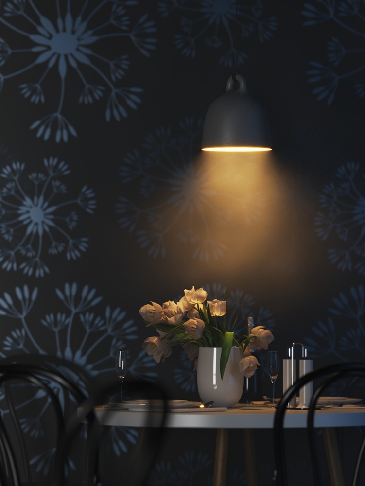
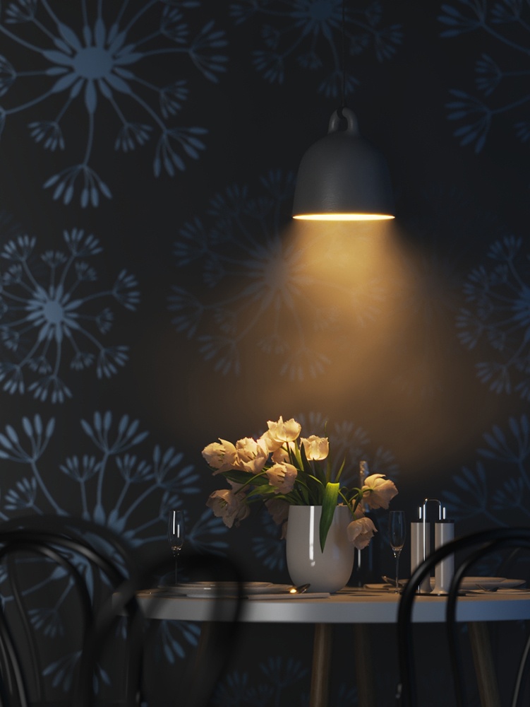
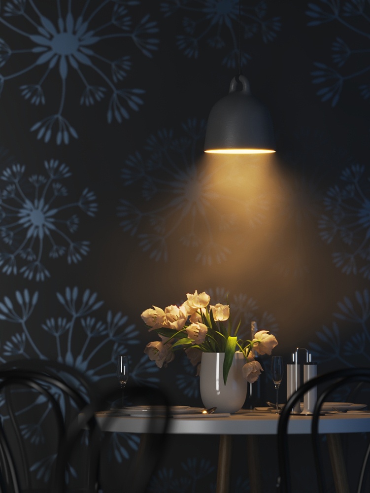
This example shows how the Power parameter affects the IES light.
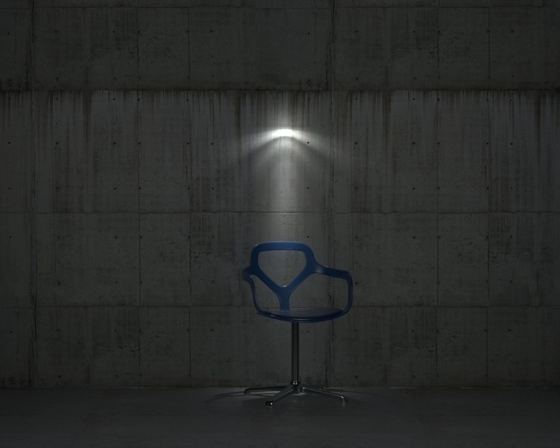
Intensity is taken from the .ies file
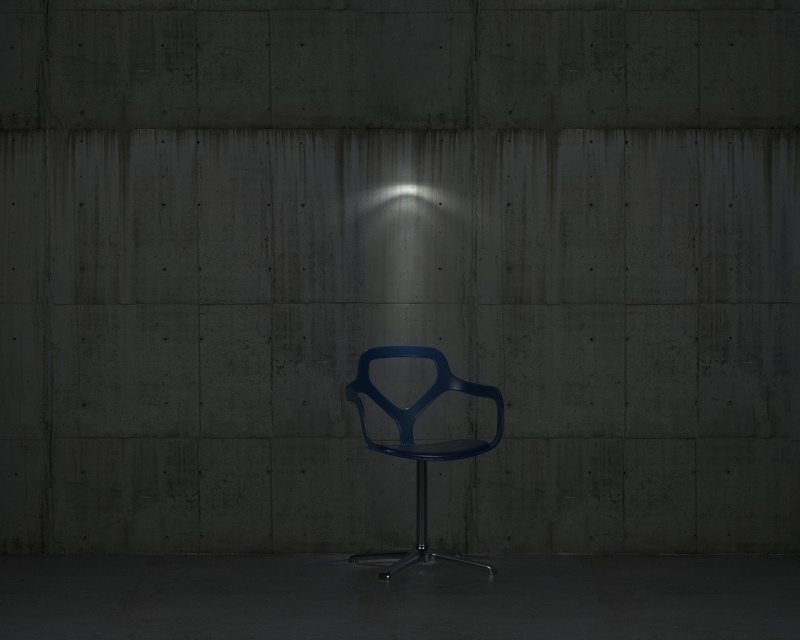
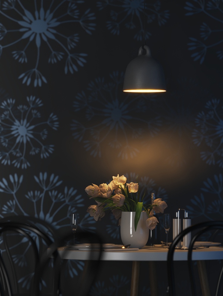
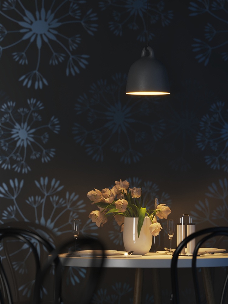
Intensity = 300
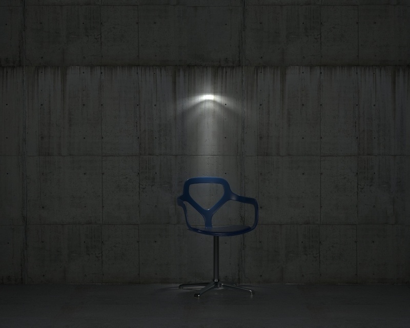
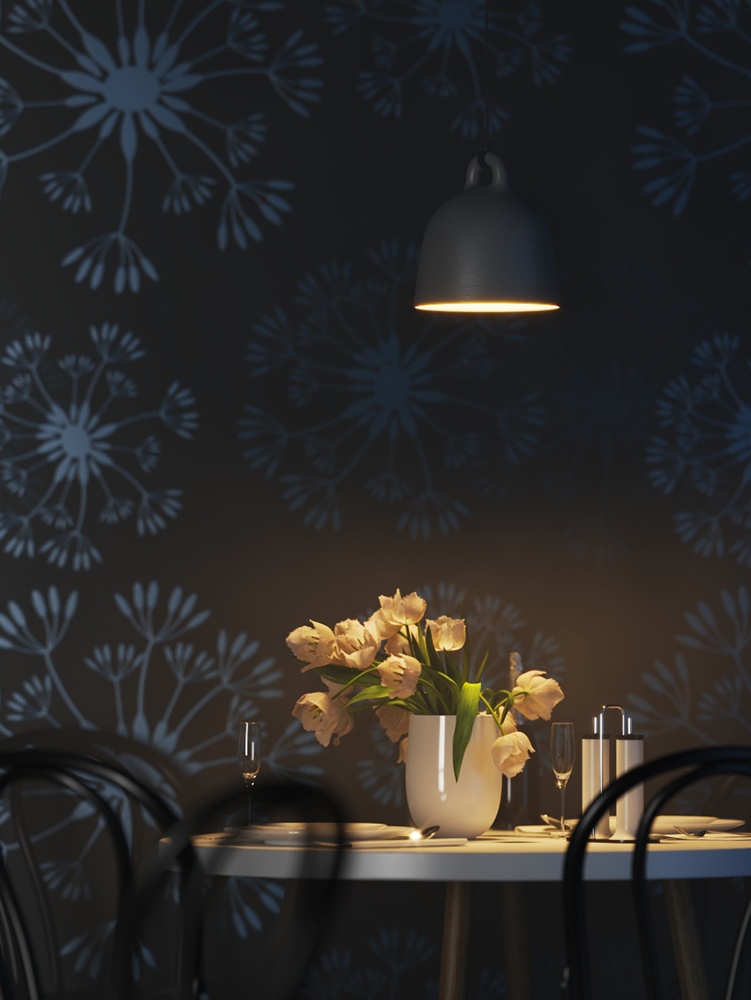
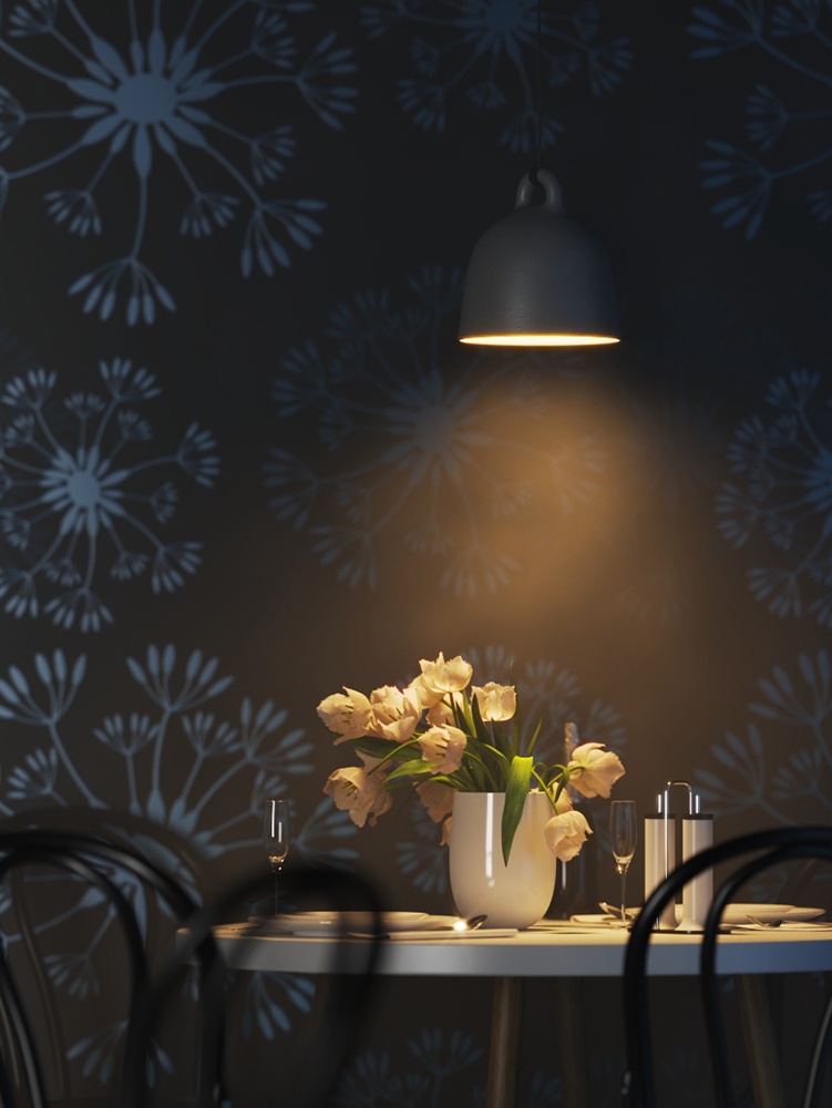
Intensity = 600
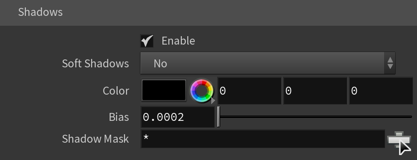
Shadows
Enabled – When enabled, the light casts shadows. Disable this option to turn off shadows for the light.
Soft Shadows – Sometimes the .ies file contains information about the physical shape and size of the bulb. When this option is enabled, the light casts shadows according to this information. Otherwise, the light casts shadows as if it was a Point Light.
Color – Controls the color of shadows for this light. Note that anything different from black is not physically correct.
Bias – Moves the shadow toward or away from the shadow-casting object (or objects). Higher values move the shadow toward the object(s) while lower values move it away. If this value is too extreme, shadows can "leak" through places they shouldn't or "detach" from an object. Other effects from extreme values include moire patterns, out-of-place dark areas on surfaces, and shadows not appearing at all in the rendering.
Shadow Mask – Specifies objects that cast shadows when light is directed at them.
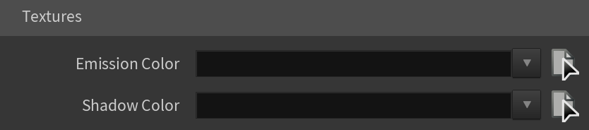
Textures
Emission Color – Specifies the color of the light rays and of the light source itself when visible in renderings.
Shadow Color – Specifies the color of the shadows produced by the light.
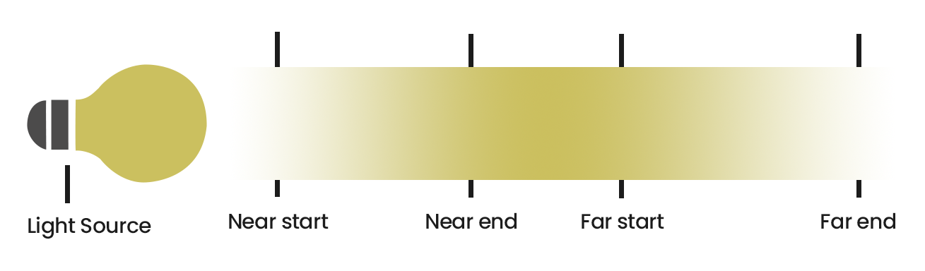
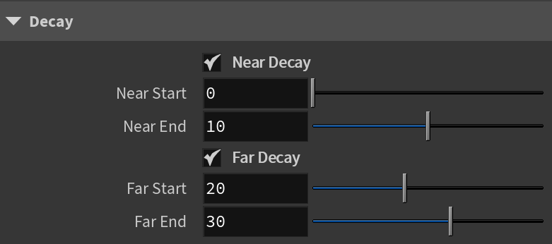
Decay
The Decay parameters determine how the light fades in and out. The Near Decay determines how light fades in. The light isn't at its maximum value at its source, but instead gradually increases until it reaches the Near End. The Far Decay determines how light fades out. The light isn't at its maximum value at its end, but instead gradually decreases after the Far Start.
Decay option is useful for creating hotspots or controlling the length of a "God Rays" effect created with Environment Fog.
Near Decay – Toggles near decay on and off. See the examples below for more information.
Near Start – Determines where the fade in starts. Anything before this point is rendered dark.
Near End – Determines where the fade in ends. After this threshold, the light is at its full value.
Far Decay – Toggles far decay on and off. See the examples below for more information.
Far Start – Determines where the fade off starts.
Far End – Determines where the light reaches a value of 0, i.e. completely fades off.
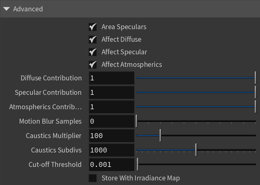
Advanced
Area Speculars – When enabled, the highlights match the shape of the light. When disabled, highlights are always calculated as if affected by a point light.
Affect Diffuse – Determines whether the light affects the diffuse properties of the materials.
Affect Specular – Determines whether the light affects the specular of the materials. This means glossy reflections.
Affect Atmospherics – Determines whether the light influences the atmospheric effects in the scene.
Diffuse Contribution – When Affect Diffuse is enabled, specifies a multiplier for the effect of the light on the diffuse component.
Specular Contribution – When Affect Specular is enabled, specifies a multiplier for the effect of the light on the specular component.
Atmospheric Contribution – When Affect Atmospherics is enabled, this value determines the amount of involvement.
Motion Blur Samples – Specifies the number of samples used to sample the light for motion blur.
Caustics Multiplier – Specifies a multiplier for the generated caustics by the selected object. Note that this multiplier is cumulative - it does not override the multiplier in the Caustics Tab of the V-Ray Render Settings.
Caustics Subdivs – Only used when calculating Caustics. Lower values mean more noisy results, but render faster. Higher values produce smoother results but take more time.
Cut-off Threshold – Specifies a threshold for the light intensity, below which the light is not computed. This can be useful in scenes with many lights, where you want to limit the effect of the lights to some distance around them. Larger values cut away more of the light; lower values make the light range larger. When this value is 0.0, the light is calculated for all surfaces.
Store With Irradiance Map – When enabled and GI calculation is set to Irradiance map, V-Ray calculates the effects of the V-Ray IES Light and stores them in the irradiance map. The result is that the irradiance map is computed more slowly but the rendering takes less time. The irradiance map can also be saved for later use.
This example shows the variances achieved by changing the Near Start parameters only. Near Start 10, Near End 60 Near Start 30, Near End 60 Near Start 50, Near End 60 This example shows the variances achieved by changing the Near End parameters only. Near Start 0, Near End 10 Near Start 0, Near End 30 Near Start 0, Near End 50 This example shows the variances achieved by changing the Far Start parameters only. Far Start 10, Far End 60 Far Start 30, Far End 60 Far Start 50, Far End 60 This example shows the variances achieved by changing the Far End parameters only. Far Start 60, Far End 60 Far Start 60, Far End 100 Far Start 60, Far End 120 This example shows some artistic lighting results achieved by using both Near and Far decay options. Near Start 0, Near End 15, Far Start 30, Far End 60 Near Start 20, Near End 35, Far Start 40, Far End 55 Near Start 30, Near End 60, Far Start 90, Far End 120
Example: Decay Near Start

Example: Decay Near End

Example: Decay Far Start
Example: Decay Far End

Example: Near and Far Decay