This tutorial guides you through the creation of an avalanche effect with Phoenix for 3ds Max, Chaos Cosmos, Chaos Scatter, and tyFlow.
Overview
This advanced-level tutorial shows you how to create an avalanche effect using Phoenix. It's recommended that you have at least basic knowledge of Phoenix simulations, animation, lighting and materials in 3ds Max. Prior experience with tyFlow is beneficial but not required.
The setup for this tutorial requires Phoenix 5.20.00, V-Ray 6 for 3ds Max 2020, Chaos Scatter 2.5 and tyFlow FREE v1.023 or newer. You can download official Phoenix and V-Ray builds from https://download.chaos.com. If you notice a major difference between the results shown here and the behavior of your setup, please reach us using the Support Form.
We will be creating two shots: one full shot, serving as an establishing shot, and a close-up shot that allows viewers to feel the impact of the avalanche.
The sample scenes provide you with the terrain and winter trees from Chaos Cosmos, populated with the help of Chaos Scatter. We use tyFlow's particles as a source to generate and simulate smoke, creating an avalanche effect with Phoenix.
For the close-up, we add an extra layer of smoke, apply camera shake, and some animated trees to enhance the visuals.
At the end of the tutorial, we color correct the image with V-Ray Frame Buffer, and we make the shot more cinematic by using Light Mix. It allows us to adjust the key-to-fill light ratio without rendering the image again.
The Download button below provides you with an archive containing the scene files.
Units Setup
Scale is crucial for the behavior of any simulation. Large-scale simulations appear to move slower, while medium and small-scale simulations display lots of vigorous movement. When you create your Simulator, have a look at the Grid rollout where the real-world size of the Simulator is shown. If it cannot be changed, you can cheat the solver into working as if the scale is larger or smaller by changing the Scene Scale option in the Grid rollout.
The Phoenix solver is not affected by how you choose to view the Display Unit Scale - it is just a matter of convenience.
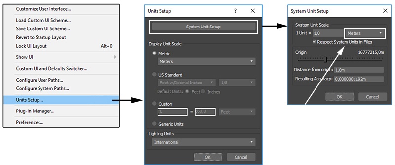
- Go to Customize > Units Setup and set the Display Unit Scale to Metric Meters
- Set the System Units to 1 Unit = 1 Meter
The spruce tree we use in the tutorial stands at approximately 7.85 meters in height, while the terrain for the full shot measures 5000.0 X 5000.0 meters.
Scene Layout
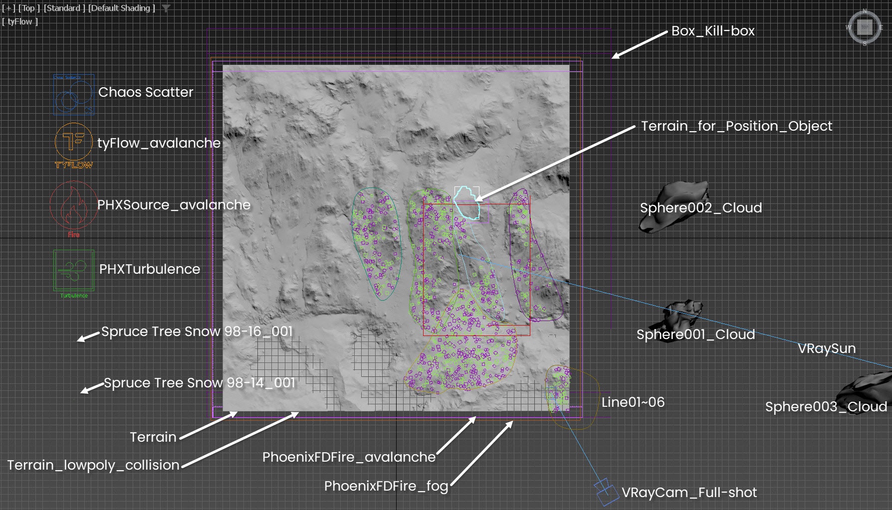
This is the top view of the final scene for the full shot, which includes the following elements:
- PHXTurbulence force to disturb the avalanche;
- PHXSource using the tyFlow_avalanche node as an emitter;
- Phoenix Fire / Smoke Simulator - PhoenixFDFire_avalanche for simulating the smoke as avalanche;
- Phoenix Fire / Smoke Simulator - PhoenixFDFire_fog for rendering the fog;
- VRayCam_Full-shot camera for rendering;
- V-Ray Sun & Sky setup for lighting;
- GeoSphere001_Cloud, GeoSphere002_Cloud and GeoSphere003_Cloud for casting shadows over the winter mountain;
- Terrain geometry;
- Terrain_for_Position_Object for the source emitter for the tyFlow_avalanche;
- tyFlow node: tyFlow_avalanche for emitting particles;
- Terrain_lowpoly_collision geometry used as collision object for the tyFlow particles;
- The Box_kill-box provides a region to define where the tyFlow particles penetrate the Terrain_lowpoly_collision and will be removed;
- Two trees from Chaos Cosmos: Spruce Tree Snow 98-14 and Spruce Tree Snow 98-16;
- A Chaos Scatter object to scatter the Spruce Tree Snow 98-14 and Spruce Tree Snow 98-16 over the Terrain geometry;
- Line01~06 are used to define the region that the terrain uses to scatter trees.
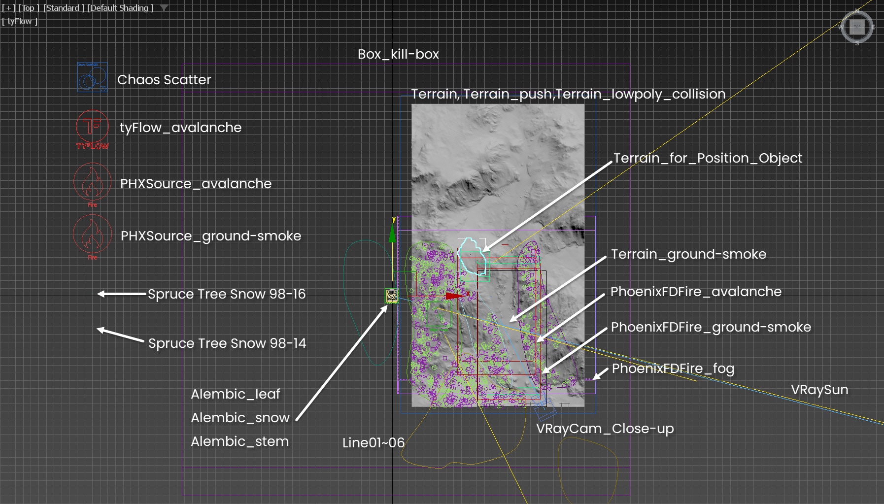
This is the top view of the final scene for the close-up shot, which includes the following elements:
PHXTurbulence force to disturb the avalanche;
PHXSource using tyFlow_avalanche as an emitter;
Phoenix Fire/Smoke Simulator - PhoenixFDFire_avalanche for simulating the smoke acting as an avalanche;
Phoenix Fire/Smoke Simulator - PhoenixFDFire_ground-smoke simulating the ground smoke acting as snow over the ground;
Phoenix Fire/Smoke Simulator - PhoenixFDFire_fog for rendering the fog;
VRayCam_Close-up camera for rendering;
Dummy_camera-shake (not shown in the screenshot) is a dummy object with a Noise controller applied to its position. VRayCam_Close-up.Target is linked to this dummy to create the camera shake effect;
V-Ray Sun & Sky setup for lighting;
Terrain geometry;
Terrain_push geometry;
Terrain_for_Position_Object for the source emitter for the tyFlow_avalanche;
tyFlow node: tyFlow_avalanche;
Terrain_lowpoly_collision geometry used as collision object for the tyflow particles;
Box_kill-box provides a region to define where the tyFlow particles which penetrate the Terrain_lowpoly_collision geometry will be deleted;
Two trees from Chaos Cosmos: Spruce Tree Snow 98-14 and Spruce Tree Snow 98-16;
A Chaos Scatter object to scatters the Spruce Tree Snow 98-14 and Spruce Tree Snow 98-16 over the Terrain geometry;
Line01~06 are used to define the region that terrain uses to scatter trees;
Alembic_leaf, Alembic_snow, and Alembic_stem are animated trees stored in Alembic file format, specifically crafted to enhance the visuals for the close-up shot.
We inherit Line01~06 from the full shot. However, in the close-up shot, due to the smaller trimmed terrain, some of these lines are not used to define the winter forest.
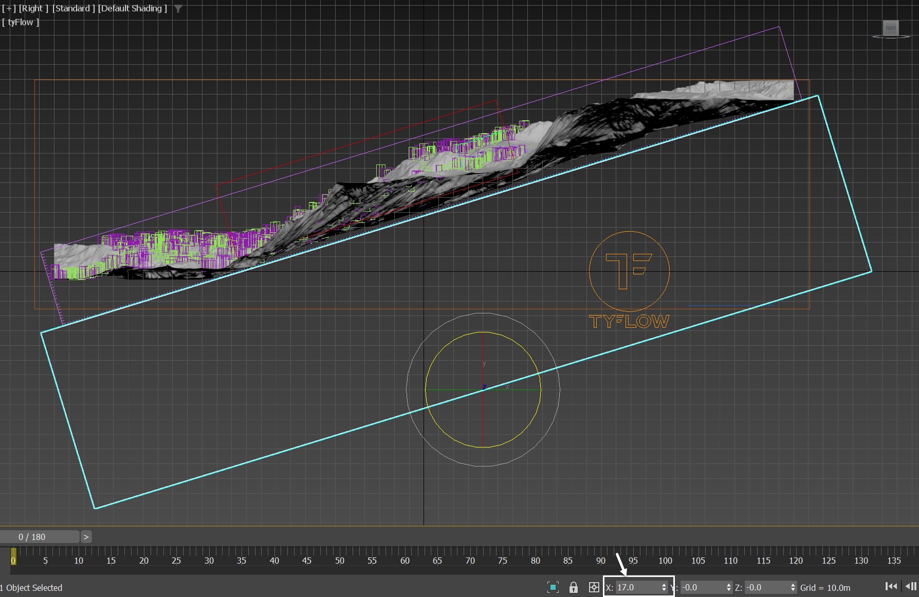
As tyFlow particles penetrate the terrain, those within the Box_kill-box are deleted by the tyFlow's Surface Test (inside) operator. It's worth noting that the Box_kill-box is rotated at a 17-degree angle on its X-axis to align with the Terrain geometry.
Set up a kill box to delete the excess particles and make the particle simulation more efficient.
In the real world, avalanches typically occur on slopes steeper than 30 degrees, with the most common instances happening on slopes ranging from 35 to 50 degrees.
Although the overall slope of the valley where the avalanche flows is not particularly steep, the specific area we select for emitting the tyFlow particles - Terrain_for_Position_Object - does have a steep slope. Therefore, the region we chose as the starting point for the avalanche is indeed valid.
Geometry Settings
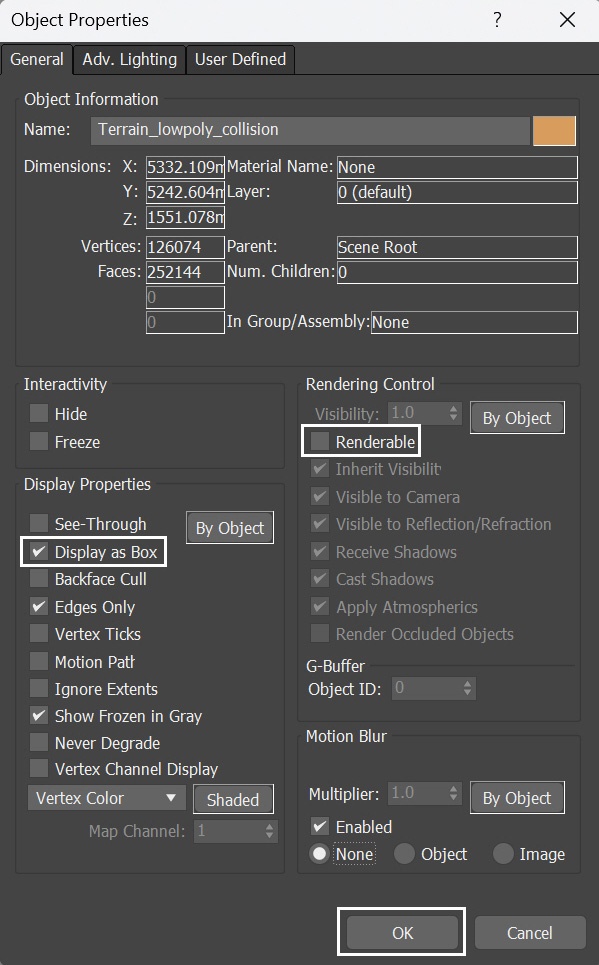
All the helper geometries used in the scenes, including Terrain_lowpoly_collision, Box_Kill-box, Terrain_for_Position_Object, Terrain_ground_smoke and Terrain_Push, have their Object Properties set to Display as Box and Renderable disabled. This configuration ensures that they remain unobtrusive in the viewport and are not visible in the final rendering.
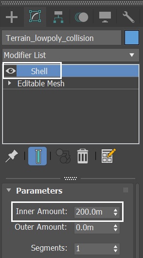
In scenes involving collision in tyFlow or Phoenix simulations, such as Terrain_lowpoly_collision, Terrain_ground_smoke, and Terrain_Push, all the helper geometries have a Shell modifier added.
The purpose of this Shell Modifier is to give volume to the planes by transforming them into actual 3D shapes with thickness. This added thickness ensures precise particle collision. Furthermore, in order to get predictable Phoenix simulation results it's best to use closed geometry objects.
Scene Setup
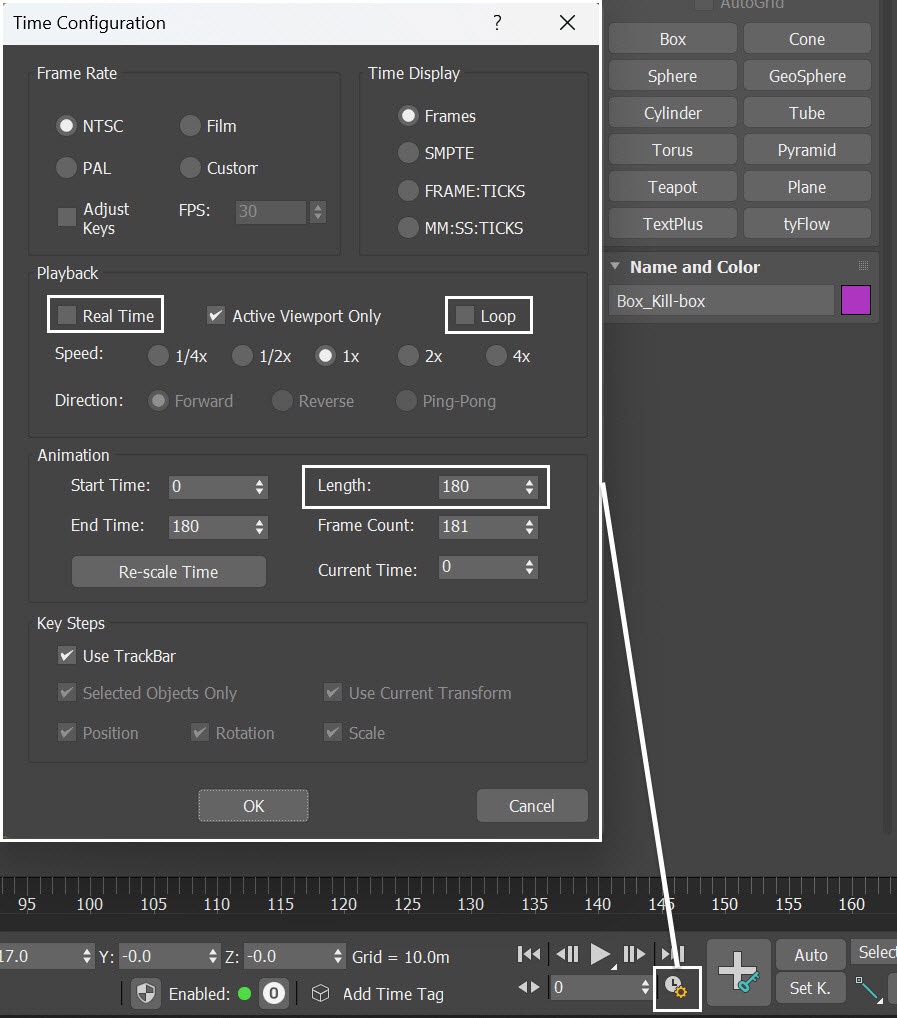
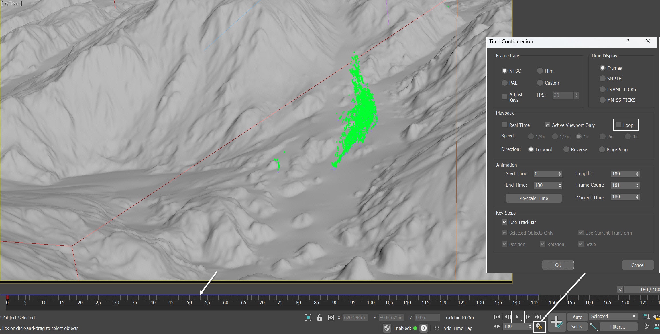
Click on the Time Configuration icon ( ![]() ) and set the Animation Length to 180, so that the Time Slider goes from 0 to 180.
) and set the Animation Length to 180, so that the Time Slider goes from 0 to 180.
Disable both the Real-Time and Loop options.
By default, 3ds Max's viewport animations play in real-time, skipping frames as needed. The playback speed depends on both hardware capabilities and scene complexity. Enabling the Real Time option in scenes with numerous particles, rigid bodies, and high-poly meshes may lead to 3ds Max not playing every frame of the animation.
Disabling the Loop ensures that the animation stops at the last frame when played, which is particularly useful when caching particle animations with tyFlow. We explore further this topic later.
This tutorial comprises of two render shots and numerous steps. Here we focus on the Phoenix-related steps only. Feel free to use the camera and light settings in the provided sample scene.
For reference, you can find the camera, tyFlow, light settings, and the Alembic trees below.
Camera Settings for Shot01
From Create Panel → Cameras → V-Ray, select the VRayPhysicalCamera and add it to the scene. Rename it to VRayCam_Full-shot.
The exact position of the Camera is: XYZ: [ 317.7, -389.1, 42.2 ].
The exact position of the Camera Target is: XYZ: [ 232.0, -241.0, 37.0 ].
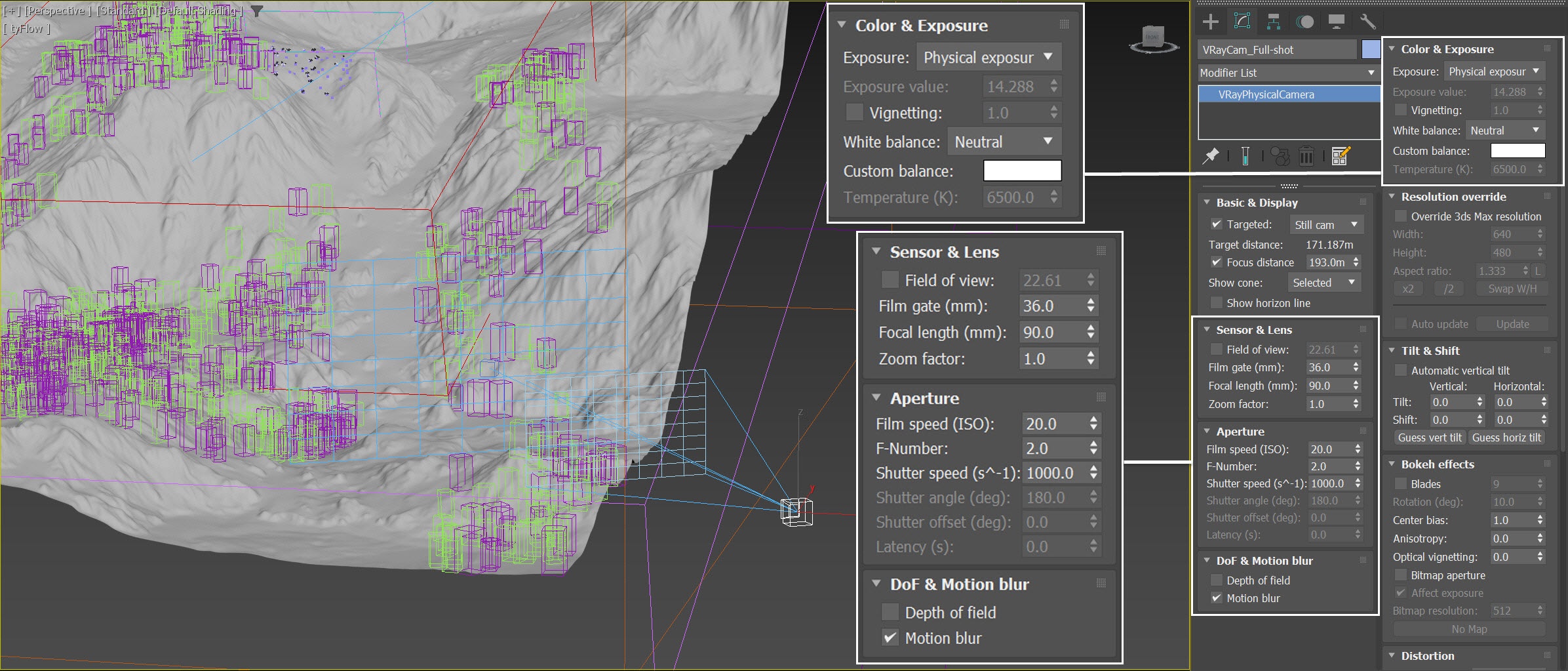
In the Sensor & Lens rollout:
Film gate is set to 36.0mm.
Focal length is set to 90.0mm.
In the Aperture rollout:
Film speed is set to 20.0.
F-Number is set to 2.0.
Shutter Speed is set to 1000.
In the DoF & Motion blur rollout, enable Motion blur.
In the Color & Exposure rollout, White balance is set to Neutral.
To make the shot more visually compelling, we have animated VRayCam_Full-shot and VRayCam_Full-shot.Target over time. Here is a table with the keyframes for the VRayCam_Full-shot.
Frame | Position (X, Y, Z) | Tangent type |
|---|---|---|
0 | 317.7, -389.1, 42.2 | Linear |
180 | 306.0, -372.0, 41.0 | Linear |
Here is a table with the keyframes for the VRayCam_Full-shot.Target.
Frame | Position (X, Y, Z) | Tangent type |
|---|---|---|
0 | 232.0, -241.0, 37.0 | Linear |
180 | 223.0, -224.0, 36.0 | Linear |
Camera Settings for Shot02
From Create Panel → Cameras → V-Ray, select the VRayPhysicalCamera and add it to the scene. Rename it to VRayCam_Close-up.
The exact position of the Camera is: XYZ: [ 198.65, -480.0, 6.8 ].
The exact position of the Camera Target is: XYZ: [ 121.8, 6.0, 40.9 ].
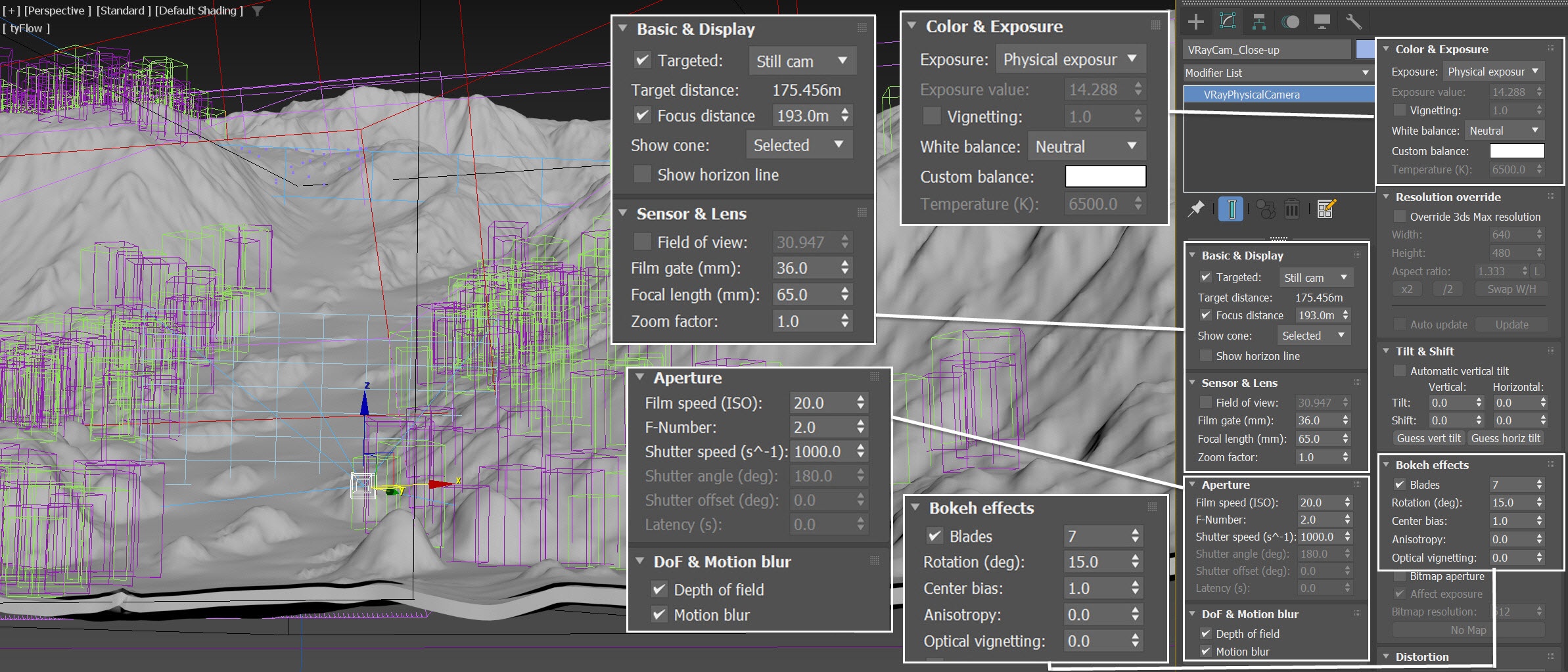
In the Basic & Display rollout, set the Focus distance to 193.0m.
In the Sensor & Lens rollout:
Film gate is set to 36.0mm.
Focal length is set to 65.0mm.
In the Aperture rollout:
Film speed is set to 20.0.
F-Number is set to 2.0.
Shutter Speed is set to 1000.0.
In the DoF & Motion blur rollout, enable both Depth of field and Motion blur.
In the Color & Exposure rollout, White balance is set to Neutral.
In the Bokeh effects tab, the Blades option is enabled and set to 7, with a Rotation of 15. Center bias is set to 1.0.
Bokeh is the result of achieving a soft, defocused background while capturing a subject with a fast lens at its widest aperture. It represents the visually pleasing quality of the out-of-focus blur in a photograph, and enabling this option subtly enhances the realism of the rendering.
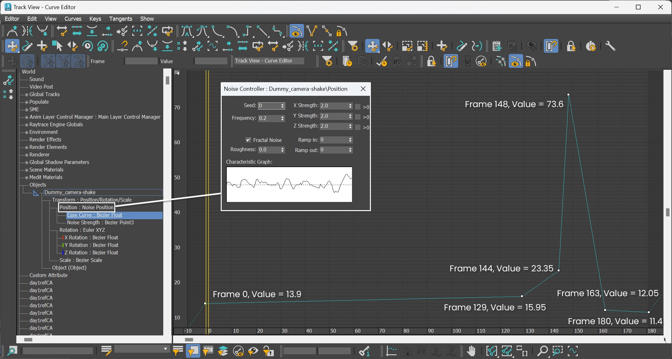
As Shot 02 is a close-up shot, we invest additional effort to heighten its impact. We introduced a Dummy object into the scene, renaming it Dummy_camera-shake, and subsequently linked VRayCam_Close-up.Target to it.
To create the camera shake effect, we initially apply a Noise Controller to the position of Dummy_camera-shake, causing a continuous, unrealistic shaking motion. To address this, we incorporate an Ease Curve on top of the Noise controller, animating the ease value over time. At frame 148, we intensify the effect to simulate the impact of the avalanche colliding with trees as it descends in the valley.
Each frame and value used are shown in the screenshots.
Lighting
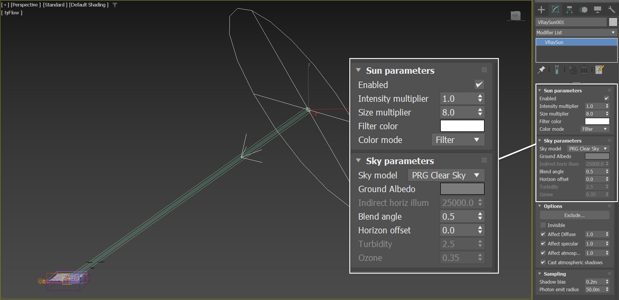
From the Create Panel go to Lights → V-Ray → VRaySun and create a VRaySun in the scene.
The exact position of the VRaySun is set to XYZ: [ 4346.0, -1138.0, 2675.0 ].
The exact position of the VRaySun Target is set to XYZ: [ 0.0, 0.0, 0.0 ].
Increase the Size multiplier to 8.0 to soften the shadows.
tyFlow Settings
This section contains information about the tyFlow settings. The setup is not discussed in-depth, it is only provided as a starting point for the Phoenix Simulation.
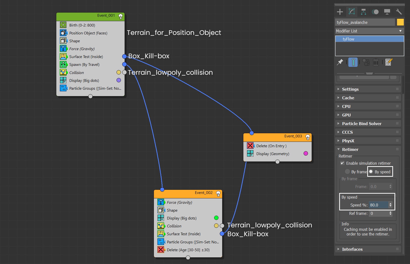
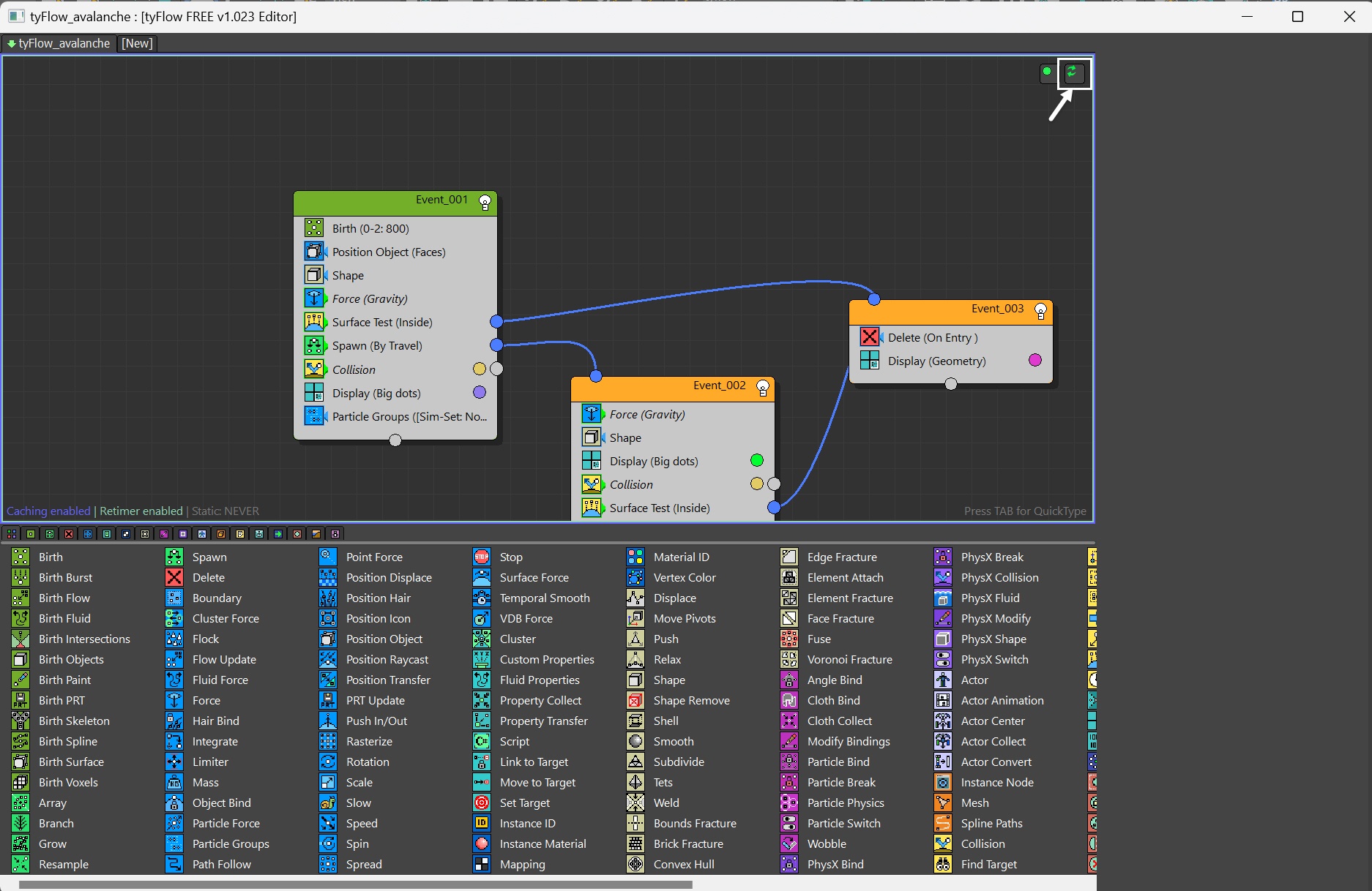
In this tyFlow configuration, we initiate Event01 particles from the Terrain_for_Position_Object. These particles follow a gravity-induced descent along Terrain_lowpoly_collsion. Concurrently, as the particles are in motion, Event02 dynamically spawns new particles using the Spawn by travel operator which are subsequently removed after a specified duration. If during this process, any particles breach the Terrain, they are promptly deleted upon entering the Box_fill-box region.
Although the velocity of the particles can be controlled by the strength of gravity, and the friction in the Collision operator, we end up fine-tuning the final velocity in the tyFlow Retimer. We check Enable simulation retimer to use By speed mode. Set Speed% to 80.0.
Shot01 and Shot02 share the same tyFlow settings, but we fine-tuned the tyFlow settings in Shot02 to make the close-up more impactful. We turn up the strength of Force (gravity) and lower the Friction in Collision, so the final particle speed is faster.
If only event01 particles are generated and used as a smoke source, you may notice intermittent puffs of smoke in the simulation results, which do not convincingly resemble an avalanche. This is why we introduce an additional event02 particle, generated using the Spawn by travel operator. This approach ensures a continuous stream of smoke, resulting in a more realistic representation.
Here is a preview animation of the particle simulation of tyFlow.
Animated Trees
To enhance the impact of shot02, we introduce some dynamic trees in the scene. We strategically position some trees near the avalanche flow and configure their rigs and dynamics using tyFlow. Since this process involves many steps and setups, and the tree rigs make the scene heavy, we streamline the tutorial by converting these animated trees into an accessible alembic format for your convenience, allowing you to concentrate on the Phoenix simulation.
We then apply these Alembic meshes with the Tree Snow 98-16 material to achieve a realistic shading.
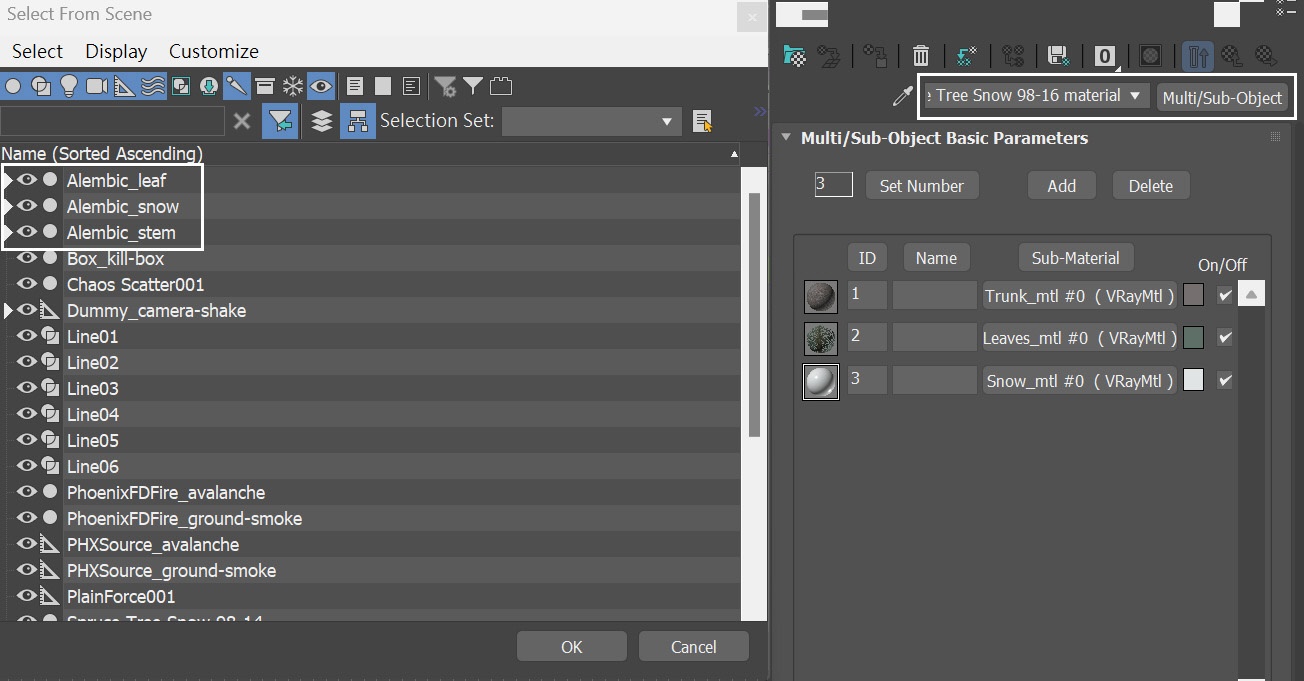
The animated trees are composed of three Alembic groups: one for the leaves, one for the snowdrifts on the tree, and one for the branches and trunks of the tree. Originally, these trees were set to be dynamic using tyFlow, allowing them to react to the force of the wind. This dynamic behavior becomes particularly evident when an avalanche begins to interact with the trees around frame 140, causing them to sway dramatically in response.
By converting the rigged trees into Alembic objects, we eliminate the need of wind, of additional ground geometry, or multiple tyMeshers, and tyflow setups for the tree rigs.
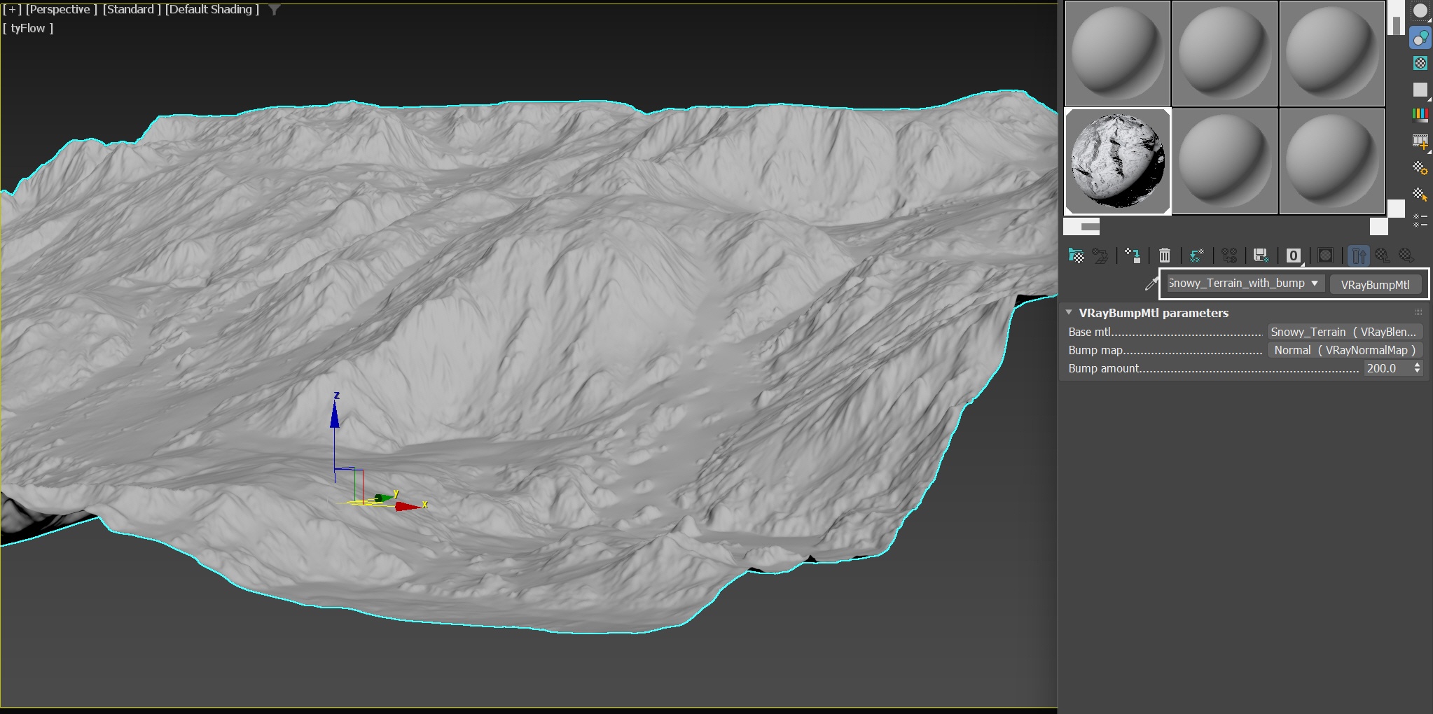
Terrain Geometry and Shading
For realistic shading, we apply Snowy_Terrain_with_bump material to it. In this setup, we use Terrain_diffuse.jpg for the diffuse slot and Terrain_normal.jpg for the bump slot. The 4K resolution of the normal map greatly enhances the details of the terrain mesh, which is especially useful for the close-up shot.
Anatomy of the Avalanche
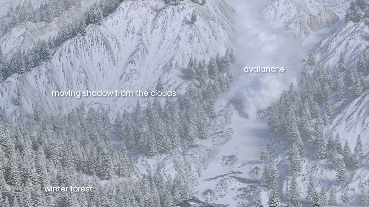
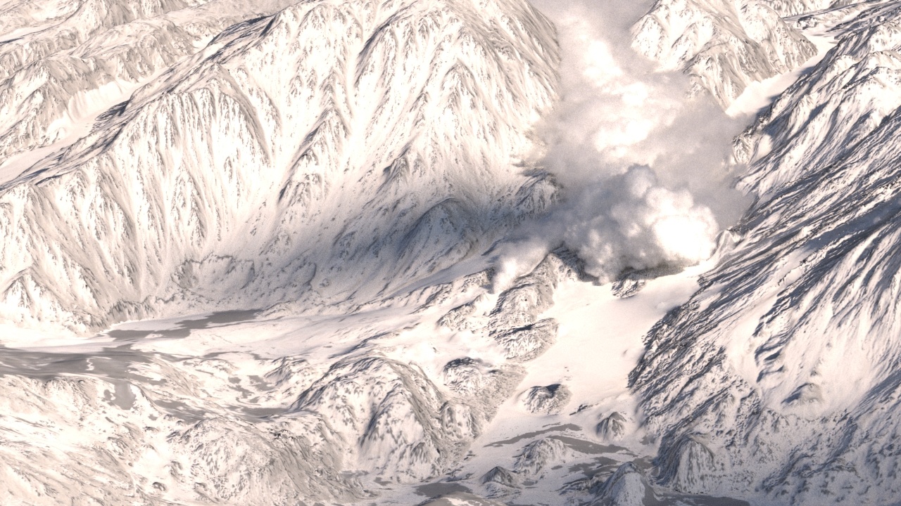
Shot 01 - Full shot
This is the establishing shot in which you see the avalanche from a distance, with winter trees scattered across the terrain. We limit the distribution of the trees to keep them out of the valley. This approach not only enhances the overall realism of the forest but also ensures that the trees do not obstruct the path of the avalanche.
Since the forest in this shot is static, it can seem rather boring. To address this, we introduce three dynamic spheres positioned above it as clouds. These spheres cast shadows onto the forest, infusing vitality and depth into the entire scene.
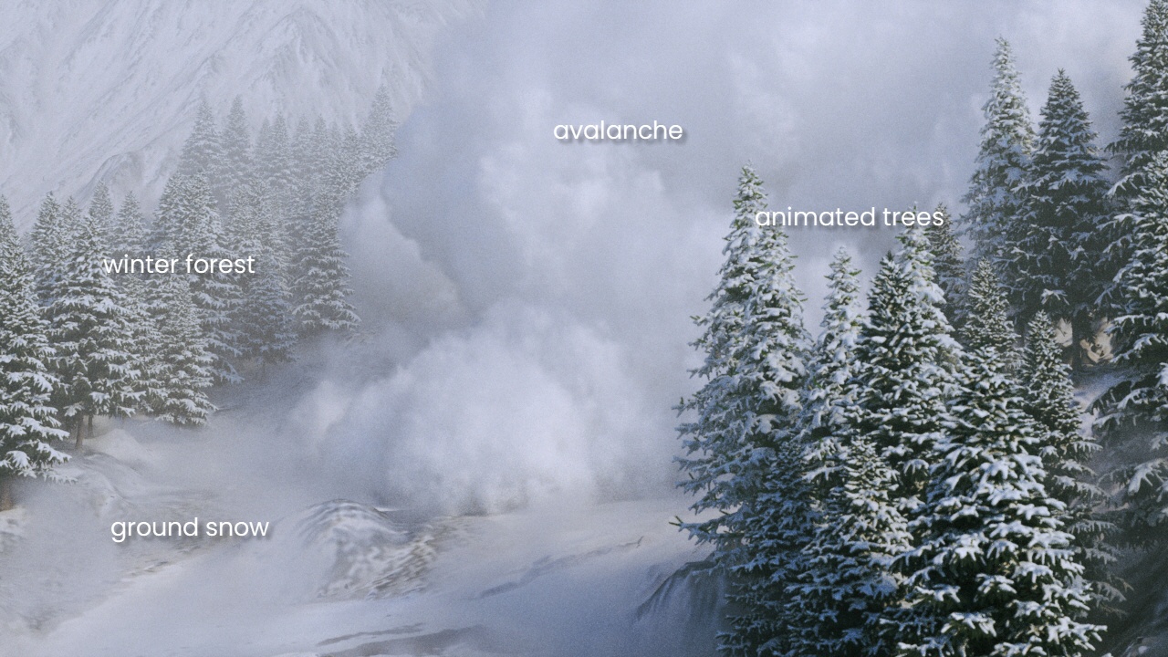
Shot 02 - Close-up
In close-up shots, the avalanche approaches the camera head-on. To heighten the impact, we incorporate dynamic trees and introduce blowing snow on the ground. This snow constantly moves toward the camera, amplifying the visual intensity.
Scattering Trees with Chaos Scatter
Let's begin by focusing on Shot 01.
Open the scene file Avalanche_shot01_max2020_start.max, which includes terrain, tyFlow, and other essential components to get started. Our initial task is to distribute winter trees across the mountain.
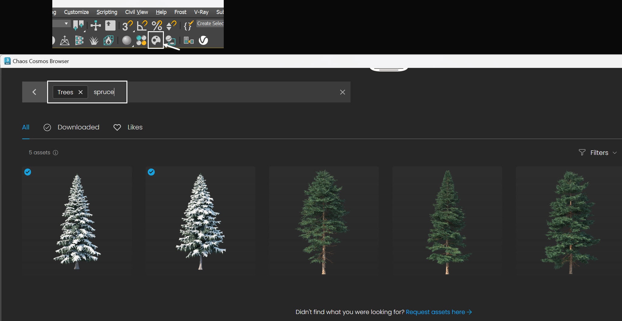
Open Chaos Cosmos browser and use the search bar to look up for trees and spruce. You'll find two relevant models for creating a winter forest: Spruce Tree Snow 98-16 and Spruce Tree Snow 98-14. Download these models and import them into your scene.
Move the trees to the side to ensure they are not visible from the camera's perspective.
The exact position of Spruce Tree Snow 98-16 in the scene is XYZ: [ -465.0, -149.0, -23.0 ].
The exact position of Spruce Tree Snow 98-14 in the scene is XYZ: [ -465.0, -233.0, -23.0 ].
Please ensure you're logged into your Chaos account to gain access to the content within Chaos Cosmos.
You can position the trees differently, as long as they are not visible from the camera's perspective.
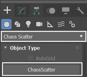
Navigate to the Create panel and select the Geometry tab. From the drop-down menu, select Chaos Scatter and create a Chaos Scatter in the scene.
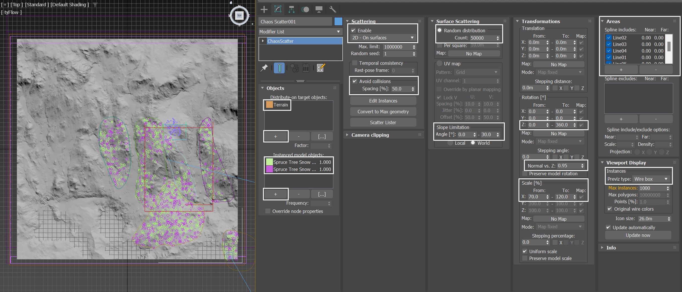
With the Chaos Scatter selected, in the Objects rollout, use the "+" button to add Terrain to the Distribute-on target objects list. Then add the Spruce Tree Snow 98-16 and Spruce Tree Snow 98-14 to the Instanced model objects list.
- In the Scattering rollout, check the Enable option. Set the mode to 2D -On surfaces.
- Enable Avoid collisions. Set the Spacing[%] to 50.0. This can avoid the tree overlapping.
- In the Surface Scattering rollout, Set the Random distribution Count to 50000.
- Set the Slope Limitation Angle from 0.0 to 30.0.
- In the Rotation section of the Transformations rollout, set the Z Rotation To to 360.0.
- To randomize the trees, in the Transformations rollout, set the Normal to Z to 0.95.
- In the Scale[%] section, set X From and To to 70.0 and 120.0, respectively.
- In the Areas rollout, use the "+" button to add Line01~06. By doing this, the tree asset is scattered within the enclosed region defined by those splines.
- In the Viewport Display rollout, set the Previz type to Box.
To create a more diverse forest, you can add multiple trees to the instanced model objects list. However, keep in mind that this may impact performance, so for this tutorial, we only use two.
Configuring the Slope Limitation Angle can enhance realism, as steep slopes in the real world are not conducive to plant growth.
Applying a 360.0° Z Rotation, adding scale randomness to the trees, and avoiding perfectly upright positions enhances the shot's realism, especially in a forest with only two tree instances, breaking the pattern and making it harder to spot identical tree faces.
The Previz type is set to Box. This makes it easier to check the dimensions of the scattered trees.
For this Chaos Scatter settings, we use the Shot 01 scene as an example. As shot 02 is intended for close-up viewing, we halve the terrain size for better performance. However, the Chaos Scatter setup remains identical to that of shot 01.
Phoenix Simulation for Shot 01
Go to Create Panel → Create → Geometry → PhoenixFD → FireSmokeSim. Rename the simulator to PhoenixFDFire_avalanche.
The exact position of the Phoenix Simulator in the scene is XYZ: [107.4, 44.7, 68.7 ].
The exact rotation of the Phoenix Simulator in the scene is XYZ: [ 17.0, 0.0, 0.0 ].
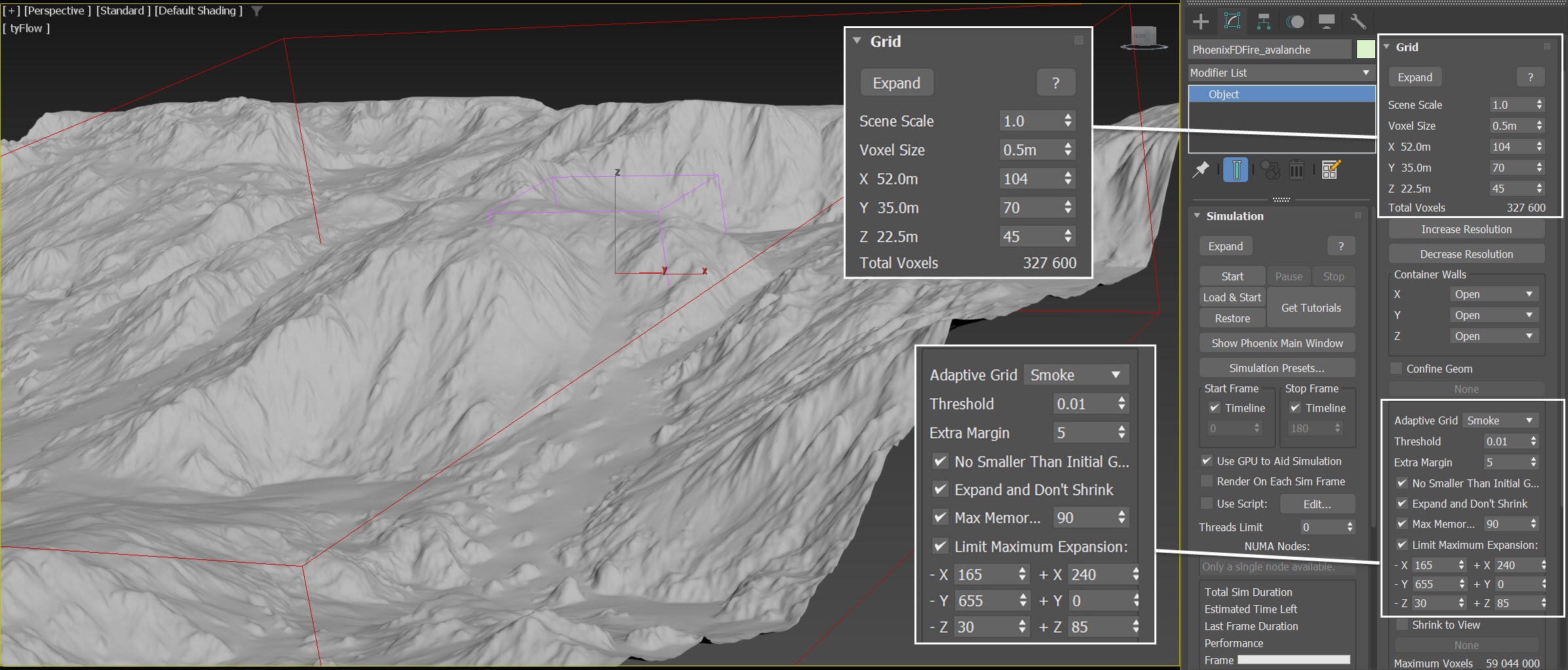
Open the Grid rollout and set the following values:
- Voxel Size: 0.50 m;
- Size XYZ: [ 104, 70, 45 ] - We keep the Simulator size small enough to roughly cover the region of Terrain_for_Position_Object where it generates tyFlow particles;
- Adaptive Grid: Smoke - the Adaptive Grid algorithm allows the bounding box of the Simulation to dynamically expand on-demand. With a Threshold of 0.001, the Simulator expands when the Voxels near the walls of the simulation bounding box reach a Smoke value of 0.001 or greater;
- Set Extra Margin to 5 to compensate for the fast movement of the smoke;
- Enable Expand and Don't Shrink - this way the Adaptive grid does not contract back when there is very thin smoke at the borders of the grid;
- Enable Max Expansion: X: (165, 240), Y: (655, 0), Z: (30, 85) - to save memory and simulation time by limiting the Maximum Size of the simulation grid.
The reason we chose to use this value for the Voxel Size is that given the resolution of the final output image, the distance from the camera to the avalanche effect, and the fact that we will be using Resimulation to increase the Grid Resolution later, this size of 0.50m is small enough to produce the visual details we need.
Ensure you set the Extra Margin to 5; otherwise, the growing Adaptive Grid won't keep up with the fast-moving smoke.
Rotate the Simulator, aligning (by 17°) it with the Terrain geometry. By doing this, we save simulation time because when the Simulator is aligned to the terrain, we use a smaller grid size.
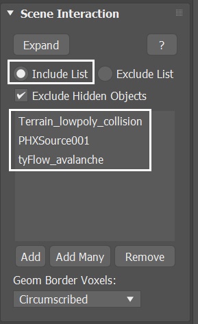
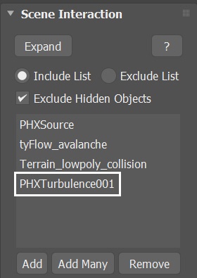
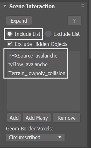
With the Simulator selected, navigate to the Scene Interaction rollout. Since there are many objects in the scene, in order to avoid any unwanted interactions, switch to the Include List and add PHXSource, tyFlow_avalanche, and Terrain_lowpoly_collision to the list. This way the simulation will interact only with the objects in the Include list.
For Geom Border Voxels, we maintain the default mode - Circumscribed. However, please note that switching to the Inscribed mode will result in more smoke in the simulation, making the smoke at the front of the avalanche appear less refined. Additionally, the avalanche flow will seem to run faster. For additional information about Geom Border Voxels, please read here.
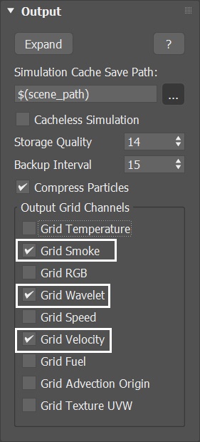
Select the Phoenix Simulator → Output rollout and enable the output of Grid Smoke, Grid Wavelet and Grid Velocity Channel.
Since we'd like to perform a Resimulation using Wavelet Turbulence to increase the simulation detail, we enable the Wavelet Grid Channel output.
Any channel that you intend to use after the simulation is complete, needs to be cached to disk. For example:
Velocity is required at render time for Motion Blur;
Grid Wavelet is used for Wavelet Turbulence when performing a Resimulation.
Adding a Fire/Smoke Source for the Avalanche
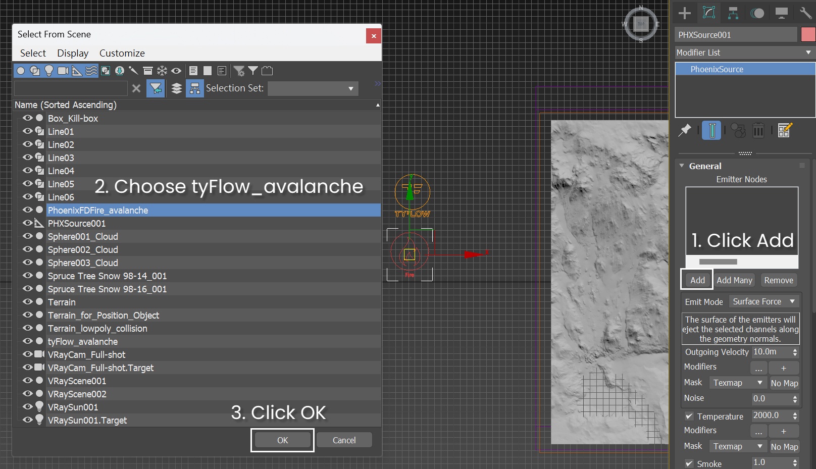
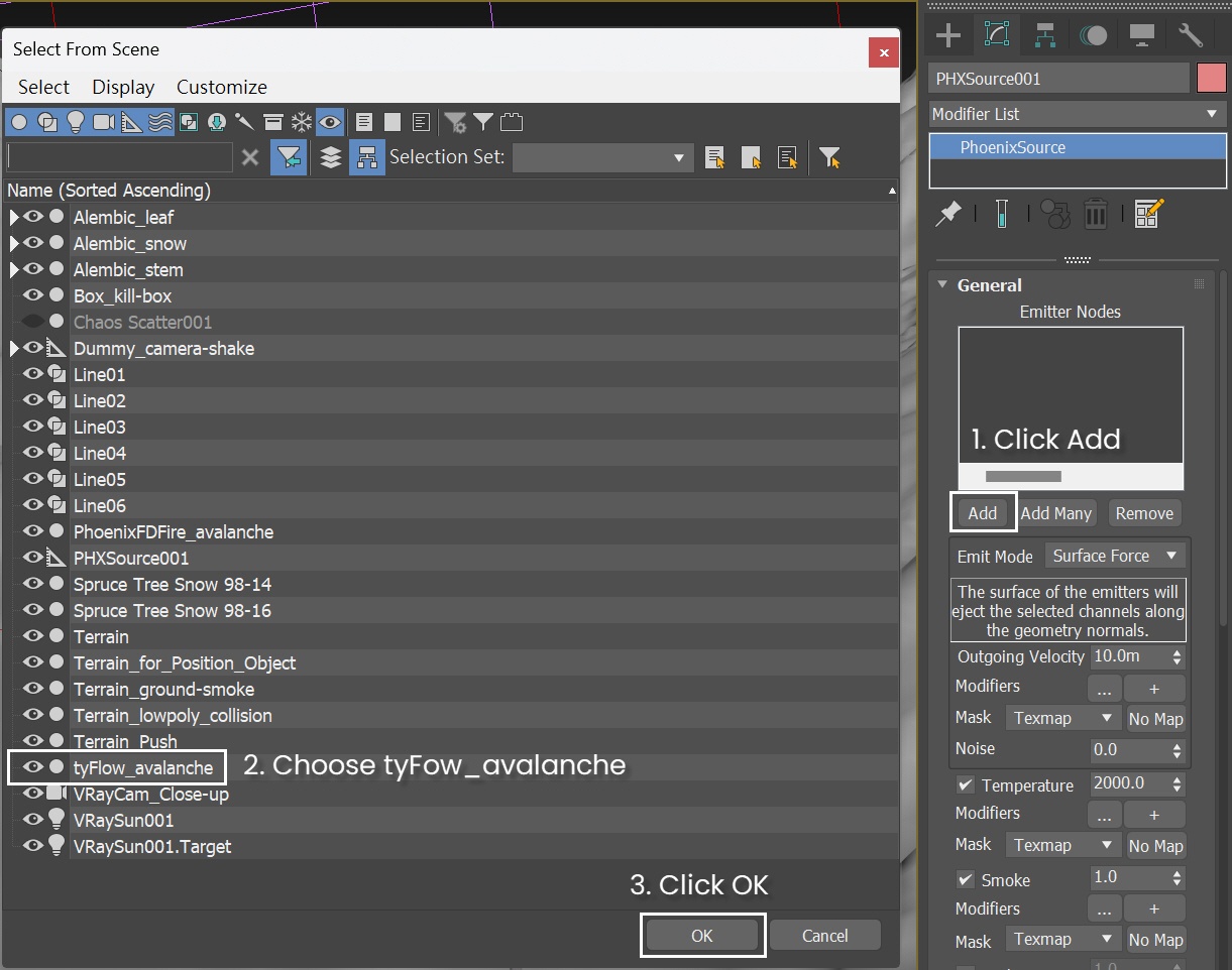
Create a Phoenix Fire/Smoke Source in the scene: Create Panel → Create → Helpers → PhoenixFD → PHXSource.
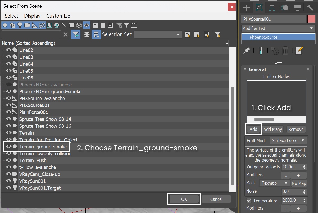
Press the Add button to choose which geometry to emit from and select the tyFlow_avalanche entry in the Scene Explorer.
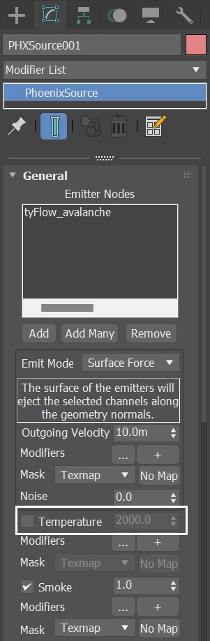
After adding the tyFlow_avalanche to the Emitter Nodes of the PHXSource, let's disable the Temperature channel since we won't need it in this simulation. Leave everything else at the default settings for now.
Initial Simulation
To focus on the fluid simulation task, we begin by hiding the Chaos Scatter object in the scene.
Additionally, clicking the Play Animation button prompts tyFlow to automatically cache the particle animation in the system memory. Once cached, you find a purple bar in the timeline. Caching the particles can enhance the efficiency of the Phoenix fluid simulation.
In the Time Configuration menu, make sure to uncheck the Loop option so the animation plays just once.
If for any reason, the particle animation in tyFlow doesn't cache properly, you can resolve this by opening the tyFlow Editor and by clicking the upper right button to clear the cache. Then click the Play Animation button to recache.
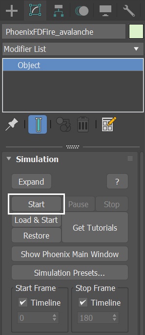
Select the Simulation rollout of the Simulator. Press the Start button to simulate.
This is a voxel preview of the current animation. The result is what looks like thick smoke billowing upwards.
Switch to PCG Solver
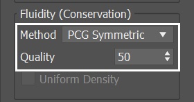
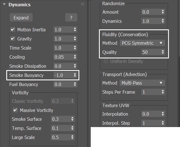
With the Simulator selected, in the Dynamics rollout change the Fluidity Method to PCG Symmetric, with a Quality of 50.
The PCG Symmetric option is the best method for smoke or explosions in general, preserving both detail and symmetry. The high Conservation Quality allows the smoke to swirl better. For more information, visit the Conservation documentation.
Quality enhances conservation strength, especially in scenarios where liquid or smoke is losing volume or when we need to intensify smoke swirling. We raise this parameter's value for improved conservation, but be cautious as it may slow down the simulation.
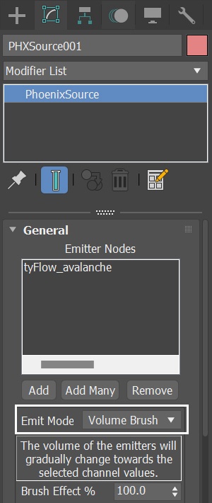
Select the PHXSource in the scene, switch the Emit Mode to Volume Brush. This mode fills the entire volume of the emitter objects with fluid. As particles flow down the hill, this makes it more suitable for simulating avalanche effects than Surface Force.
With those new settings, run the simulation again.
This is a voxel preview of the current animation. While the simulation behaves more like an avalanche now, it appears somewhat weak.
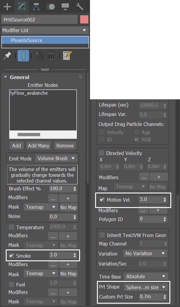
With the PHXSource selected, increase Smoke amount to 3.0. Increase Motion Vel. to 3.0. As for the Particle Shape, switch it to Sphere and set a custom size of 0.7 meters.
With those new settings, run the simulation again.
A larger Smoke Amount, combined with volumetric shading settings, helps us achieve a more convincing avalanche shading.
Motion Velocity Effect allows you to control the impact of a moving object over the fluid. The motion could be caused by translation, rotation, scaling of the object, or by vertex animation where the vertices should push the fluid with their vertex velocities. The higher the value is, the stronger the fluid reaction to the body's motion is. Therefore, to make the smoke more dramatic, we increase the Motion Velocity Effect parameter of the PHXSource to a value of 3.0.
The custom size of the Sphere in the Particle Shape indirectly influences the emitted smoke amount. A larger size value creates larger particles, resulting in more smoke emission. If you desire more smoke, increasing this parameter is one of the available options.
This is a voxel preview of the current animation. While there is now a more robust smoke presence, there still isn't the desired avalanche dynamics with snow accumulating downward.
Adjusting Smoke Buoyancy
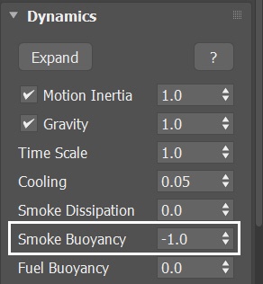
To make the smoke sink down, select the Fire/Smoke Simulator, navigate to the Dynamics rollout, and set the Smoke Buoyancy to -1.0.
With these updated Dynamics settings, rerun the simulation.
If you prefer the smoke to descend more quickly, you can further reduce the Smoke Buoyancy.
This is a voxel preview of the animation.
Adding Phoenix Turbulence
To bring more realism to the avalanche, let's add some forces to the scene. In order to give the smoke even more details, we add Phoenix Turbulence in order to introduce some turbulence in the fluid.
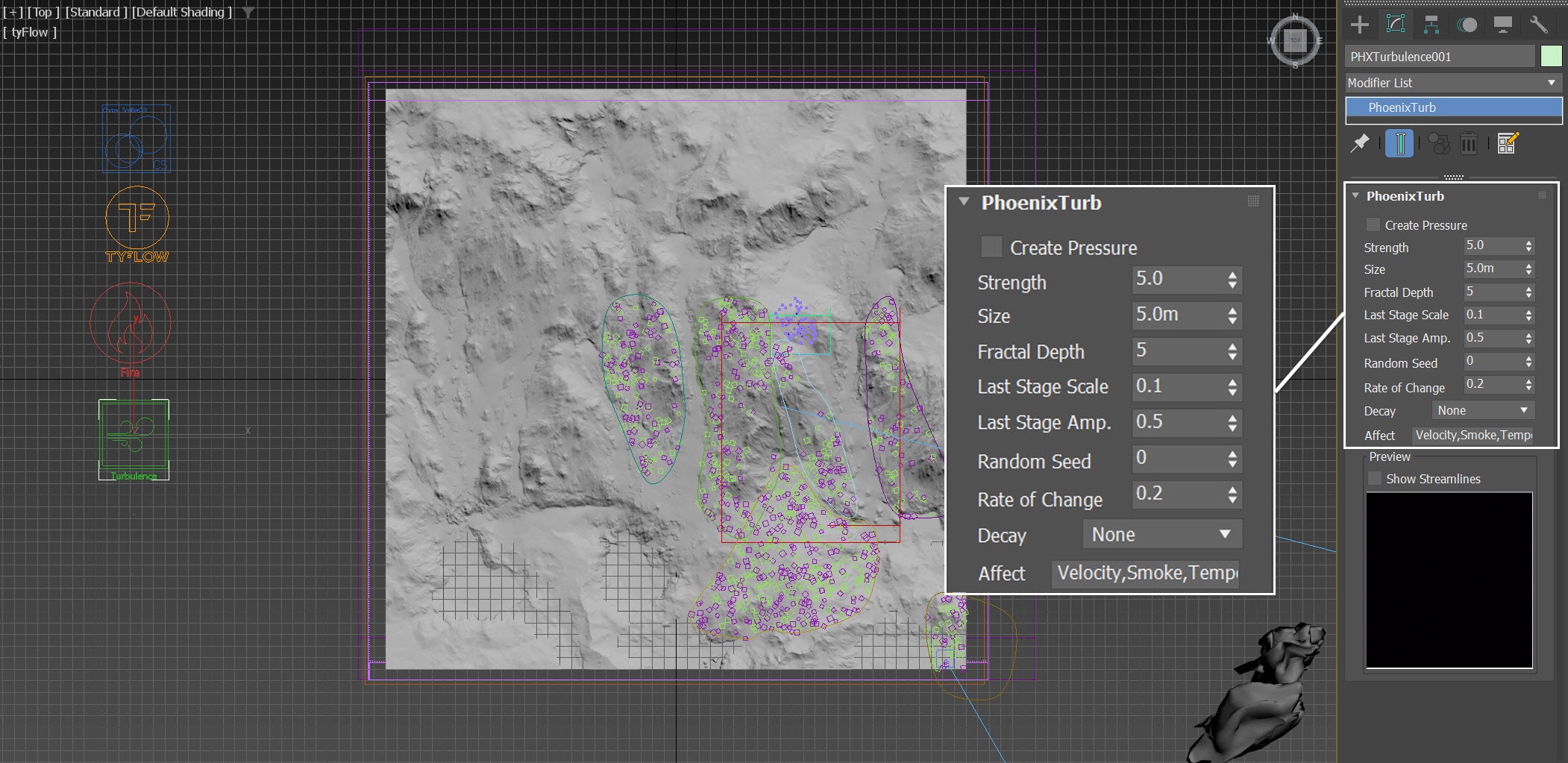
Go to the Create panel > Helpers > PhoenixFD and click on PHXTurbulence. Create a Phoenix Turbulence in the scene.
- Set the position to XYZ: [ -465.0, -47.0, -23.0 ].
- Set the Strength to 5.0.
- Set the Size to 5.0m.
- Set the Fractal Depth to 5.0.
- Reduce the Rate of Change to 0.2.
When choosing the size for the Phoenix Turbulence, we set it to 10 times the Simulator Voxel Size. This ensures the proper scale, and it is potent enough to generate the desired detail without being excessively strong. For more organic and subtle details, increase the Fractal Depth to 5. To prevent the animation from moving too quickly, decrease the Rate of Change to 0.2.
As we add the Phoenix Turbulence to the scene, make sure you add it to the Scene Interaction Include List of the Simulator, too; otherwise, the force won't have any effect.
Run the simulation again.
This is a voxel preview of the current animation. Now more details in the avalanche start to appear.
Resimulation
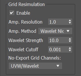
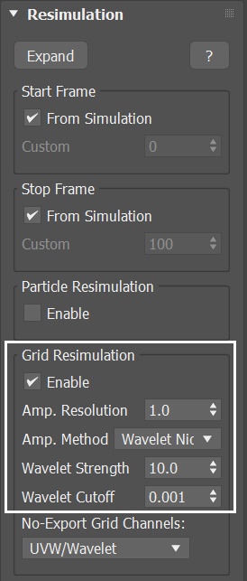
Open the Phoenix Simulator → Resimulation rollout and enable Grid Resimulation.
Note that when you enable Resimulation, Phoenix reads the cache files for preview and rendering from the Resimulation Output Path, instead of the regular Output. Don't worry if the Viewport goes blank and the preview disappears - you can always go back to the original cache files by disabling the Resimulation.
Set the Amp.Resolution to 1.0. This parameter is used to increase the resolution of the grid during the Resimulation process.
Set Amp. Method to Wavelet Nice and Wavelet Strength to 10.0.
Press Simulator → Simulation rollout → Start to begin the Resimulation.
The high value of Wavelet Strength is assigned to enhance wavelet turbulence through Resimulation, ensuring we obtain sufficient details for the avalanche effect.
Wavelet Nice use wavelet turbulence to generate fine details, requiring the export of a Grid Wavelet channel to serve as the base simulation cache files.
You can set the Amp.Resolution to an even higher value to get a more detailed result.
This is a voxel preview of the current animation. As you can see, after the Resimulation, we get more details in the avalanche, while maintaining the overall pattern formation from the base simulation.
Volumetric Shading for Shot 01
Run a test render from frame 165. It helps us assess what changes are needed to improve the look of the shading.
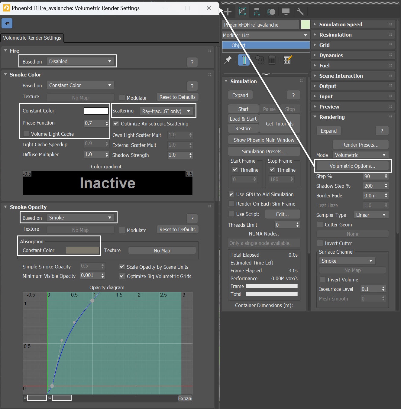
Select the Simulator, and go to its Volumetric Render Settings.
- Set the Fire Based on option to Disabled - we don't need any fire in this scene.
- Change the Smoke Color to pure white of RGB (255, 255, 255).
- Set the Scattering to Ray-tracing (GI only) - this mode uses physically accurate scattering of light rays and produces the most realistic results, though it is a bit slower to render.
- Set the Phase Function to 0.7.
- Set the Smoke Opacity's Based on option to Smoke.
- Set the Absorption Color to brown color of RGB (51, 48, 38).
Increasing the value for Light Cache Speedup speeds up the render, but it also lowers the quality of the Volume Light Cache. If dark cubic grid artifacts start forming on the smoke, the parameter is set too high. For more information, visit the Volumetric Rendering In-Depth page.
In this case, disable the Volume Light Cache, as it produces cleaner render result.
The Phase Function controls the direction in which the light scatters inside the volume. The default value of 0 means isotropic scattering, that is, light is scattered in all directions. A positive value means forward scattering, while a negative value means backscattering.
Here we want to render a realistic avalanche that is made up of ice. The light should scatter forward, that's why we give it a value of 0.7.
Although the composition of clouds and avalanches is not exactly the same, the Phase Function value we use here is identical to the one used in the previous cloudscape tutorial. Therefore, the value of 0.7 is employed more for aesthetic reasons rather than being necessarily based on real physical data.
Note that Phase Function values very close to 1.0 or -1.0 produce very directional scattering that is invisible from most angles, so such values are not recommended. When rendering with a Phase Function different than 0 and Volume Light Cache is enabled, the rendered result is brighter. The Phase Function is ignored when the Scattering is set to Approximate or Approximate+Shadows.
The Absorption Color not only influences the color of volumetric shadows and the tint of objects seen through the volume but also affects its transparency. Brighter colors make the volume more transparent, while darker colors make it more opaque. When adjusting its color value, remember this relationship. In this case, we set the absorption color with a value of 51, which is darker than the default value of 96. Consequently, it will appear more opaque than the default setting.
In general, when you assign a blue color to the Absorption Color, you achieve smoke with a yellow tint and bluish shadows. Conversely, if you choose a yellow color for the Absorption Color, the smoke exhibits a blue tint, and its shadows appear yellowish. In this case, we opt for a dark yellow Absorption color as an artistic choice. You have the freedom to select other colors based on your preference.
The Opacity curve for Smoke collaborates with the source's Smoke Amount to achieve the desired snowpack shading. Nevertheless, you have the flexibility to fine-tune the Opacity curve to match your preferences.
Alternatively, you can load up a render preset from the Avalanche_render_preset.tpr file, that is provided in the sample scene.

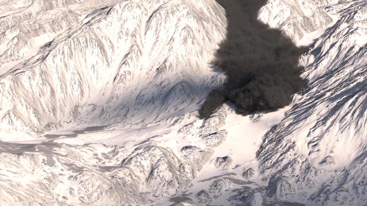
With the new volumetric settings, run a test render from frame 165. The avalanche shading has been improved for a more realistic look, but to enhance the scene's atmosphere, we aim to introduce fog in the next step.
Create a Fire/Smoke Simulator as Fog
In order to simulate the fog in the scene we can use a Fire/Smoke Simulator instead of a V-Ray Environment fog.
Let's create one now. Go to Create Panel > Create > Geometry > PhoenixFD > FireSmokeSim. Rename it to PhoenixFDFire_fog.
The exact position of the Phoenix Simulator in the scene is: XYZ: [ -22.0, 0.0, 0.0 ].
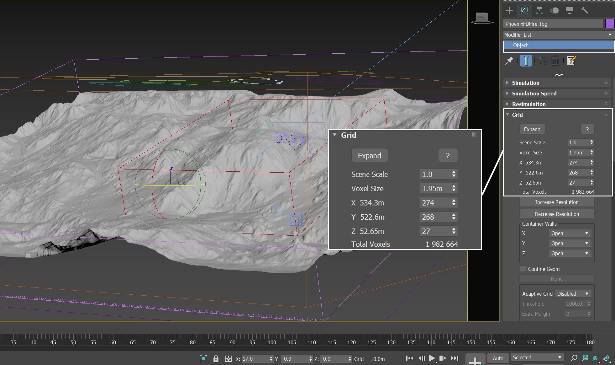
Open the Grid rollout and set the following values:
- Voxel Size: 1.95 m
- Size:
X: 274
Y: 268
Z: 27
While a comparable outcome can be attained using V-Ray Environment Fog, seamless blending of Phoenix Simulator nodes with V-Ray Environment Fog requires switching to the Volumetric Geometry render mode for the Phoenix Simulator. This might result in slower rendering in many scenarios. Therefore, we use another Fire/Smoke Simulator to act as fog, ensuring faster rendering and proper blending of the atmospheric effects.
Volumetric Shading for Shot 01 - Fog
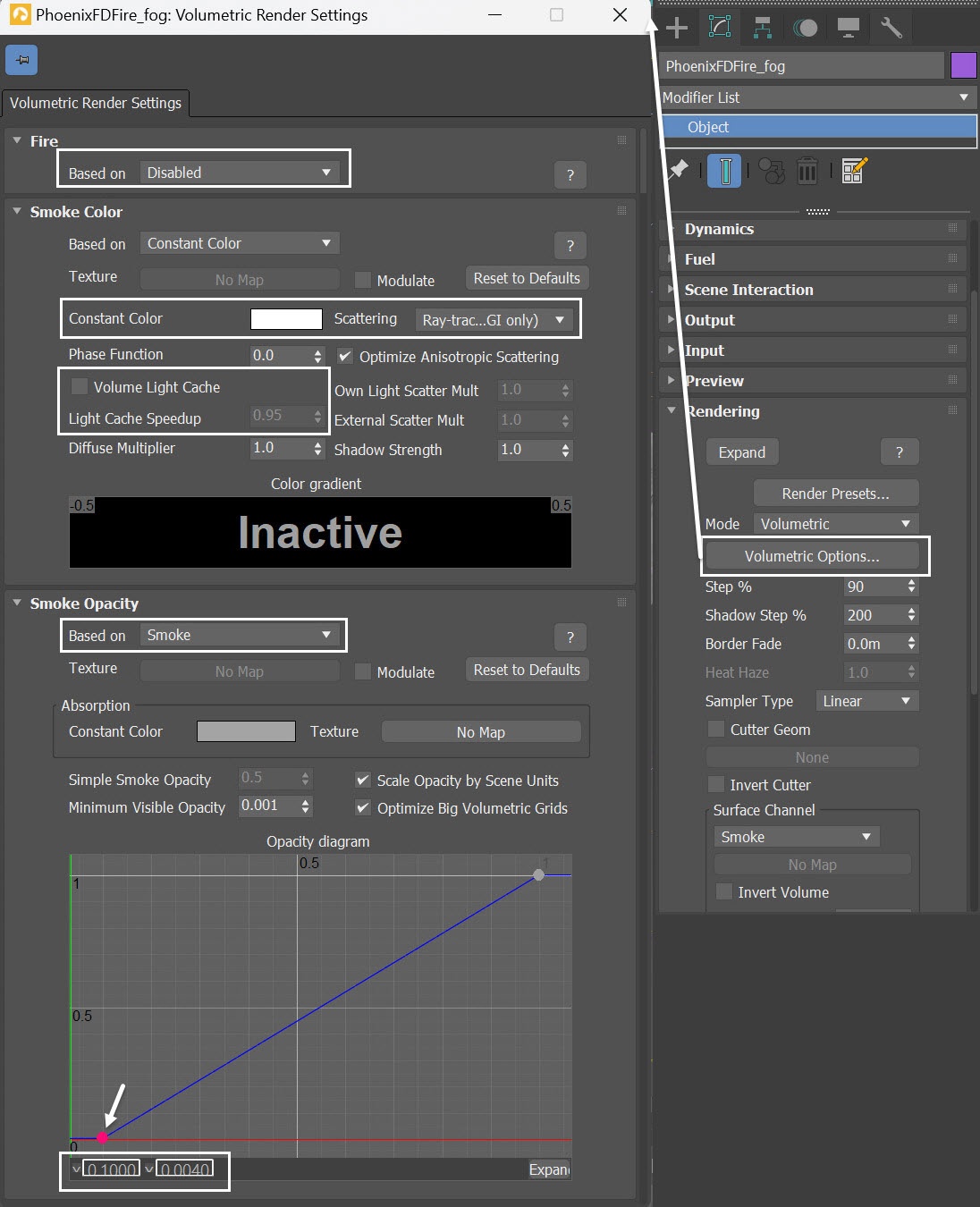
Select the Phoenix Fire/Smoke Simulator, and go to its Volumetric Render Settings.
- Set the Fire Based on option to Disabled - we don't need any fire for the fog effect.
- Change the Smoke Color to pure white of RGB (255, 255, 255).
- Set the Smoke Opacity Based on option to Smoke.
- In the Opacity diagram, adjust the Y value of the first key point to 0.004. This way we can create a fog volume without actually running the simulation.
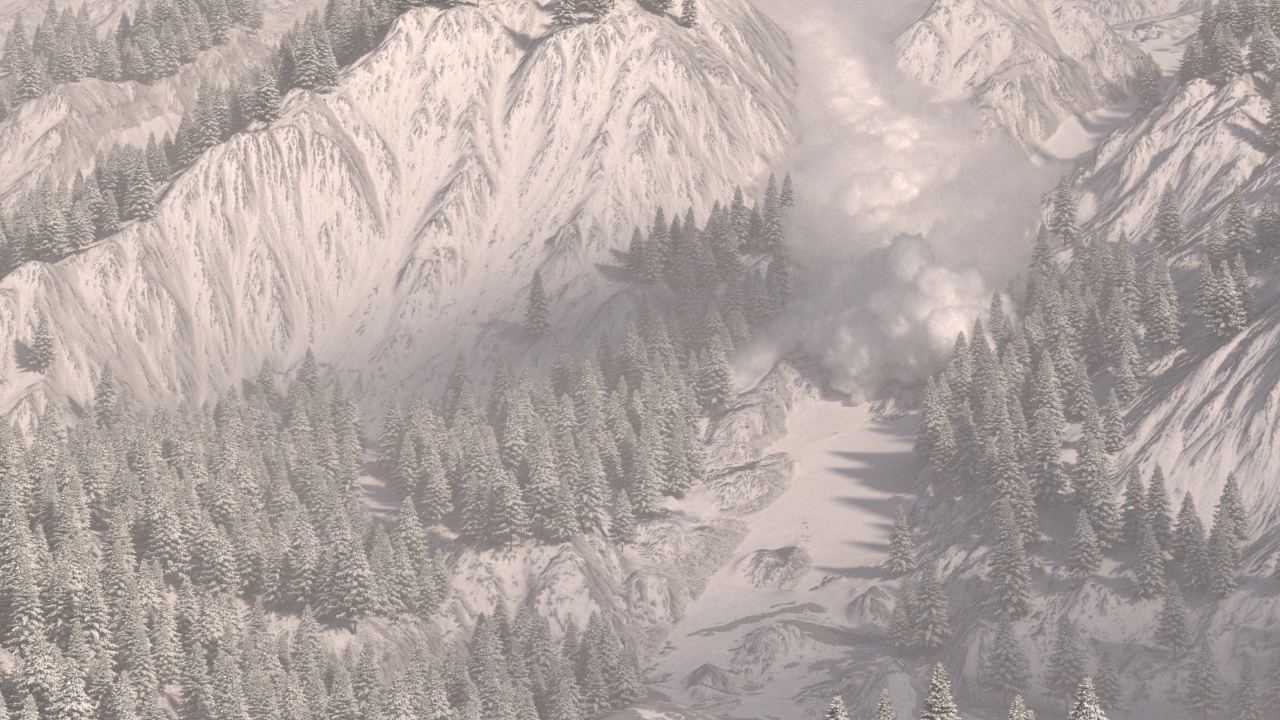
Let's unhide Chaos Scatter and run a test render with the newly added ambient fog. Now, you can observe a convincing avalanche flowing down the valley amidst white snow and a wintry forest. It just requires some color correction.
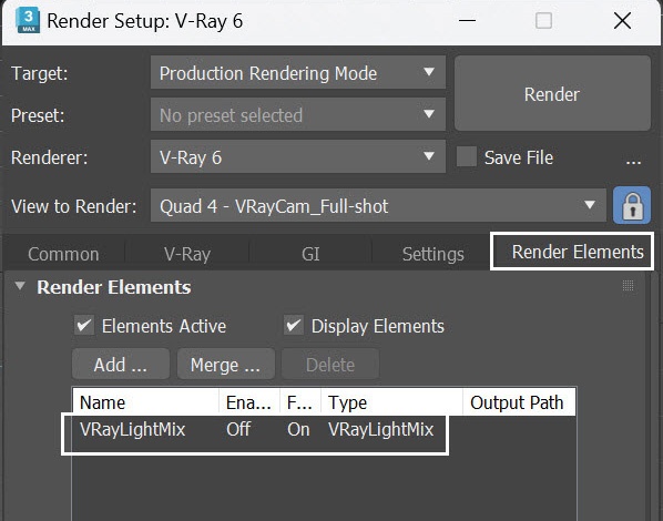
Render Elements
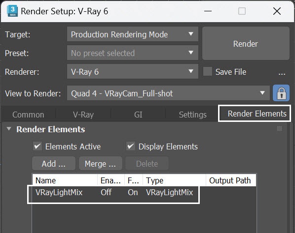
In the Render Setup > Render Elemets tab, add VRayLightMix render elements. This is necessary for relighting the scene in the VFB.
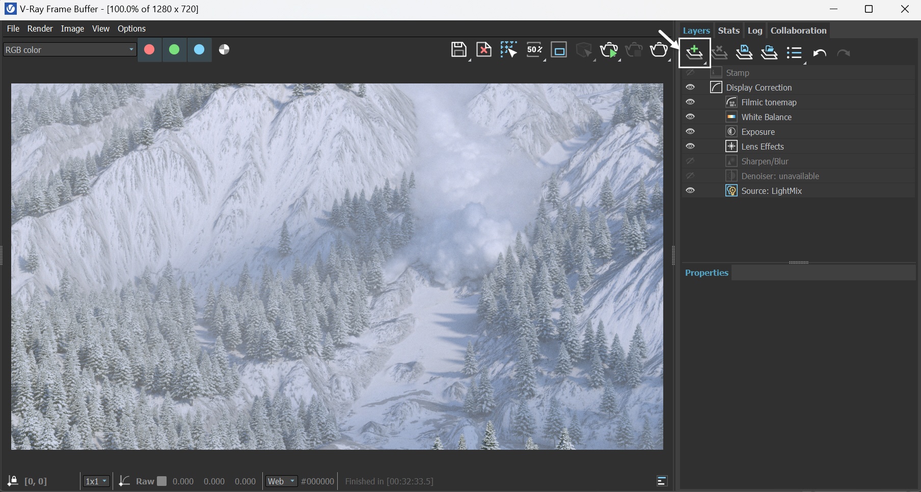
V-Ray Frame Buffer and Relighting with LightMix
Open the V-Ray Frame Buffer and use the Create Layer icon ( ![]() ) to add layers for Exposure, White Balance and Filmic Tonemap.
) to add layers for Exposure, White Balance and Filmic Tonemap.
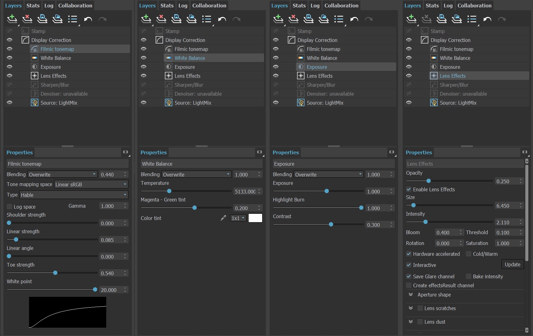
The image is rendered using the V-Ray Frame Buffer. In the current example, the color corrections and post effects are set to:
Filmic Tonemap:
- Blending, Override: 0.440
- Type: Hable
- Shoulder strength: 0.000
- Linear strength: 0.085
- Linear angle: 0.000
- Toe strength: 0.540
- White point: 20.000
White Balance:
- Temperature: 5133.000
- Magenta - Green tint: 0.200
Exposure:
- Exposure: 1.000
- Highlight Burn: 1.000
- Contrast: 0.300
Lens Effects:
- Opacity: 0.250
- Size: 6.450
- Intensity: 2.110
- Threshold: 0.100
The Filmic Tonemap render element simulates a camera film's response to light, making the scene more realistic.
Feel free to use other values for the post effects, depending on your preferences.
This step shows how to use LightMix to adjust the keylight (VRaySun) to fill-light (VRaySky) ratio. Reducing the weight of VRaySun and adjusting the color of both VRaySun and Environment contributes to a more cinematic shot.
Select the Source: LightMix layer and switch its mode from RGB to LightMix.
Decrease the weight of the VRaySun001 layer to 0.5.
- Change VRaySun001 layer to orange color of sRGB (1.000, 0.914, 0.802).
- Change Environment layer to light blue color of sRGB (0.908, 0.946, 1.000).
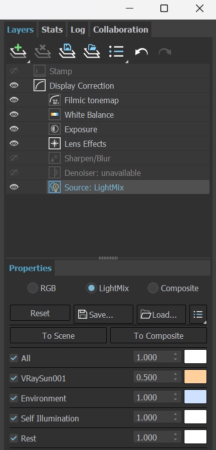
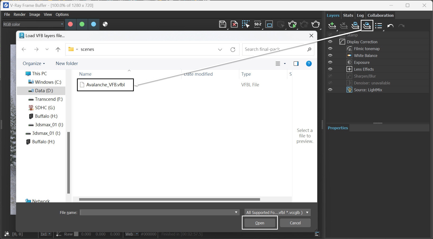
Alternatively, you can load up a layer tree Preset from the Avalanche_VFB.vfbl file that is provided in the sample scene.
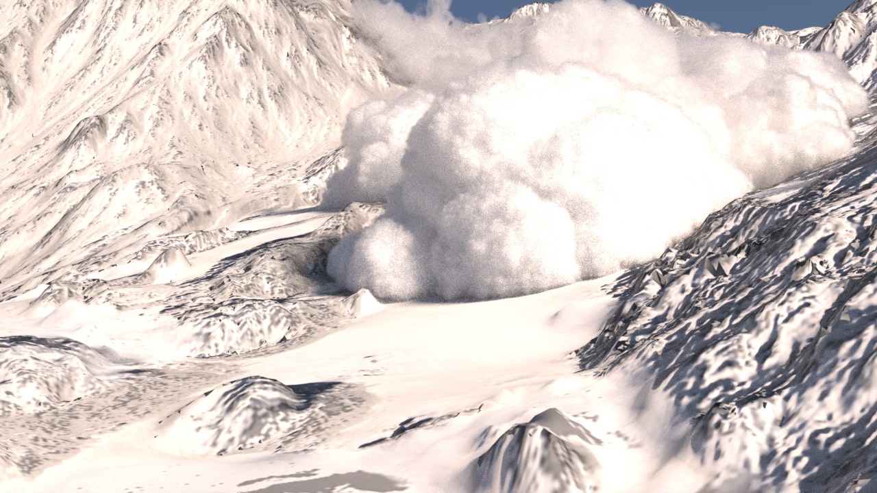
Here is the final rendered result (from frame 90 to frame 180) for Shot01 of the avalanche scene.
For aesthetic reasons, we chose not to render the entire animation, particularly during the initial phase when particles generate from tyFlow, and the smoke emission starts.
Phoenix Simulation for Shot 02
Now that we have completed Shot 01, we can begin working on Shot 02. Open the scene file Avalanche_shot02_max2020_start.max, which includes terrain geometries, tyFlow, scattered trees with Chaos Scatter, and other essential components to get started.
Go to Crete Panel → Create → Geometry → PhoenixFD → FireSmokeSim. Rename the simulator to PhoenixFDFire_avalanche.
The exact position of the Phoenix Simulator in the scene is XYZ: [107.4, 44.7, 68.7 ].
The exact rotation of the Phoenix Simulator in the scene is XYZ: [ 17.0, 0.0, 0.0 ].
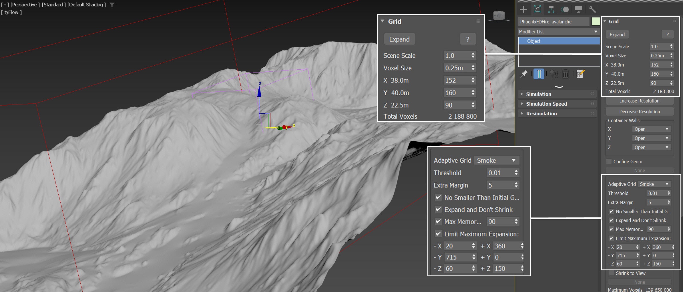
Open the Grid rollout and set the following values:
- Voxel Size: 0.25m;
- Size XYZ: [ 152, 160, 90 ] - We keep the simulator size small enough to roughly cover the region of Terrain_for_Position_Object where it generates tyFlow particles;
- Container Walls: Open to X, Y and Z;
- Adaptive Grid: Smoke - the Adaptive Grid algorithm allows the bounding box of the simulation to dynamically expand on-demand. With a Threshold of 0.01, the Simulator expands when the Voxels near the walls of the simulation bounding box reach a Smoke value of 0.01 or greater;
- Set Extra Margin to 5 to compensate for the fast movement of the smoke;
- Enable Expand and Don't Shrink - this way the Adaptive grid does not contract back when there is very thin smoke at the borders of the grid;
- Enable Max Expansion: X: (20, 360), Y: (715, 0), Z: (60, 150) - to save memory and simulation time by limiting the Maximum Size of the simulation grid.
Shot 02 is intended for close-ups, which is why we reduce the Simulator's Voxel Size to half, at 0.25m, in comparison to the 0.5m Voxel Size in Shot 01. A smaller Voxel Size results in a higher Grid Resolution, providing more detailed simulations.
Ensure you set the Extra Margin to 5; otherwise, the growing Adaptive Grid won't keep up with the fast-moving smoke.
Rotate the Simulator, and make it align (by 17°) with the Terrain geometry. By doing this, we save simulation time due to also using a smaller Grid Size.
In the Dynamics rollout of the Simulator, inherit the settings from shot 01.
- Set the Smoke Buoyancy to -1.0.
- Set the Fludity Method to PCG Symmetric, Quality to 50.
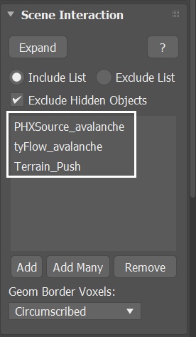
With the Simulator selected, navigate to the Scene Interaction rollout. Since there are many objects in the scene, in order to avoid any unwanted interactions, switch to the Include List and add PHXSource, tyFlow_avalanche, and Terrain_lowpoly_collision to the list.
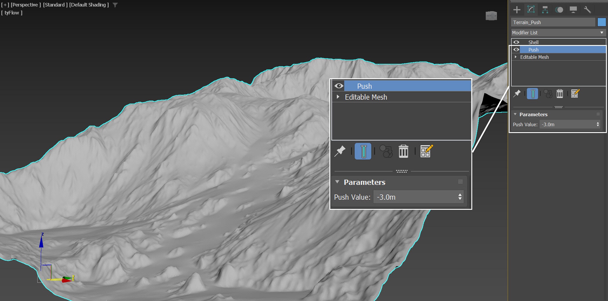
In the next step, we replace the Terrain_lowpoly_collision with Terrain_Push, which is essentially the same geometry, except that Terrain_Push has a Push modifier applied, causing the geometry to push inward for 3 meters.
Select the Phoenix Simulator → Output rollout and enable the output of Grid Smoke, Grid Wavelet and Grid Velocity Channel.
Since we'd like to perform a Resimulation using Wavelet Turbulence to increase the simulation detail, enable the Wavelet Grid Channel output.
Any channel that you intend to use after the simulation is complete needs to be cached to disk. For example:
Velocity is required at render time for Motion Blur;
Wavelet is used for Wavelet Turbulence when performing a Resimulation.
Adding a Fire/Smoke Source for the Avalanche
Create a Phoenix Fire/Smoke Source in the scene: Create Panel → Create → Helpers → PhoenixFD → PHXSource. Rename it to PHXSource_avalanche.
Press the Add button to choose which geometry to emit and select the tyFlow_avalanche entry in the Scene Explorer.
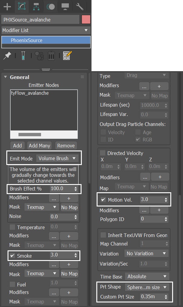
Set up the PHXSource_avalanche's properties:
Set the Emit Mode to Volume Brush.
Disable the Temperature.
Set the Smoke to 3.0.
- Increase the Motion Vel. to 3.0.
- Set the Prt Shape to Sphere, custom size. Set the Custom Prt Size to 0.35m.
Note that the Custom Prt Size for PHXSource_avalanche is set to 0.35m for shot 2, while for shot 01, it is set to 0.7m. Considering that the Simulator Voxel Size is 0.5m for shot 01 and roughly half that, at 0.25m, for shot 02, the Custom Prt Size we set for shot 02 matches the visual appearance of smoke in shot 01.
Initial Simulation
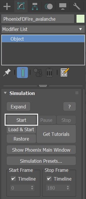
Select the Simulation rollout of the PhoenixFDFire_avalanche Simulator. Press the Start button to simulate.
Here's a voxel preview of the current animation.
Volumetric Shading for Shot 02 - Avalanche
Shot02 shares the same Volumetric Shading setup as shot01, so there's no need to set it up from scratch. You can load up a render preset from the Avalanche_render_preset.tpr file, that is provided in the sample scene.
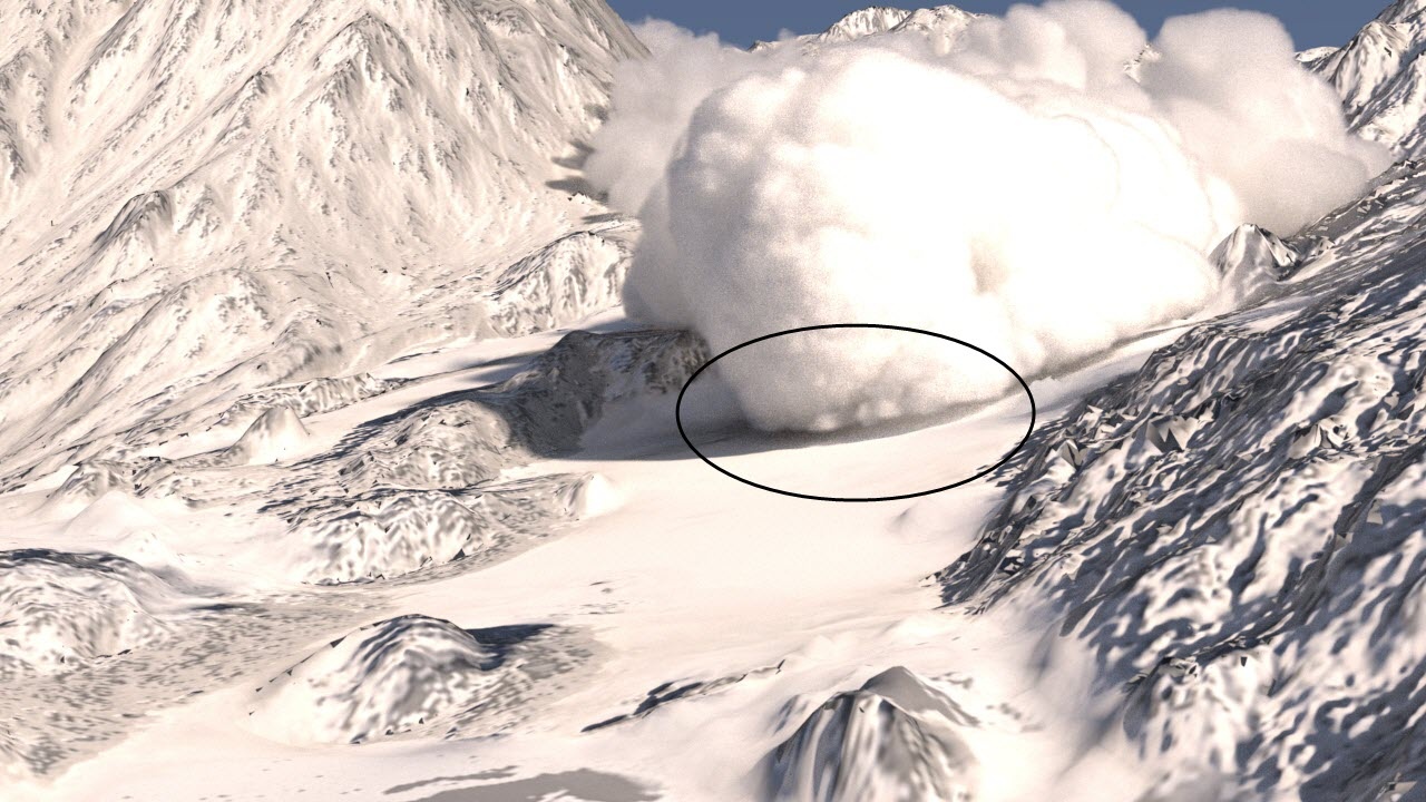
Here is a test render of frame 110. You can see a visible gap between the avalanche and the terrain.
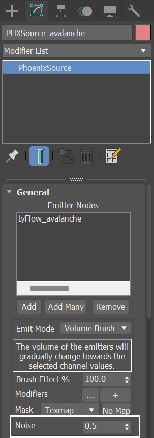
With the PHXSource_avalanche selected, increase the Noise to 0.5.
The Noise parameter in a Fire/Smoke Source varies the Brush Effect (%) across the volume of the emitting geometry. The variation also changes over time. By increasing this value, we introduce some randomness in the smoke emission, making the avalanche effect more dramatic.
With the PhoenixFDFire_avalanche Simulator selected, go to the Scene Interaction rollout. Remove Terrain_lowpoly_collision from the Include List and add Terrain_Push to the list.
With the new settings, let's run the simulation again.
While setting Geom Border Voxels to Inscribed is one method to prevent gaps between the smoke and the terrain, it's insufficient to address the issue in this case. This is because, in the real world, terrains like this are typically covered by snow and aren't solid geometry. We need to devise an alternative approach to simulate the avalanche running down the terrain and seamlessly blend it with the soft snow on the ground—this involves replacing Terrain_lowpoly_collision with Terrain_Push.
Terrain_Push is the same geometry derived from Terrain, with the addition of a Push modifier. In this example, we set the Push Value to -3.0m, but you can adjust this value depending on your preference. By using the Terrain_Push geometry, we can avoid having a gap between the smoke and the terrain geometry. Terrain_Push is the object involved in Scene Interaction in the simulation, while the Terrain is used for rendering purposes only.
This is a voxel preview of the current animation.
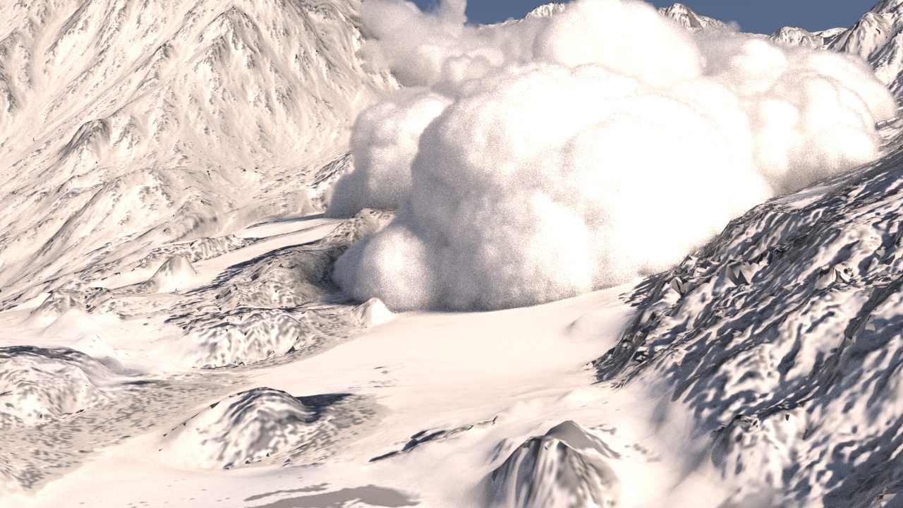
Here is a test render of frame 110.
Resimulation
Open the Phoenix Simulator → Resimulation rollout and enable Grid Resimulation.
Note that when you enable Resimulation, Phoenix reads the cache files for preview and rendering from the Resimulation Output Path, instead of the regular Output. Don't worry if the Viewport goes blank and the preview disappears - you can always go back to the original cache files by disabling the Resimulation.
Set the Amp.Resolution to 1.0. This parameter increases the resolution of the grid during the Resimulation process.
Set Amp. Method to Wavelet Nice and Wavelet Strength to 10.0.
Select the Simulator → Simulation rollout → Start to begin the Resimulation.
Shot 02's Resimulation setting follows the settings used in Shot 01. This setup guarantees the generation of a detailed avalanche.
This is a voxel preview of the current animation.
After resimulation, run a test render of frame 110.
Phoenix Simulation for Shot 02 - the Ground Smoke
Now that we have achieved the primary avalanche effect for shot 02, in order to enhance its visual impact, let's also create an additional smoke effect that emits snow from the ground and directs it towards the camera.
Go to Create Panel → Create → Geometry → PhoenixFD → FireSmokeSim. Rename the simulator to PhoenixFDFire_ground-smoke.
The exact position of the Phoenix Simulator in the scene is XYZ: [ -8.5, 0.25, 0.0 ].
The exact rotation of the Phoenix Simulator in the scene is XYZ: [ 17.0, 0.0, 0.0 ].
Rename it to PhoenixFDFire_ground-smoke.
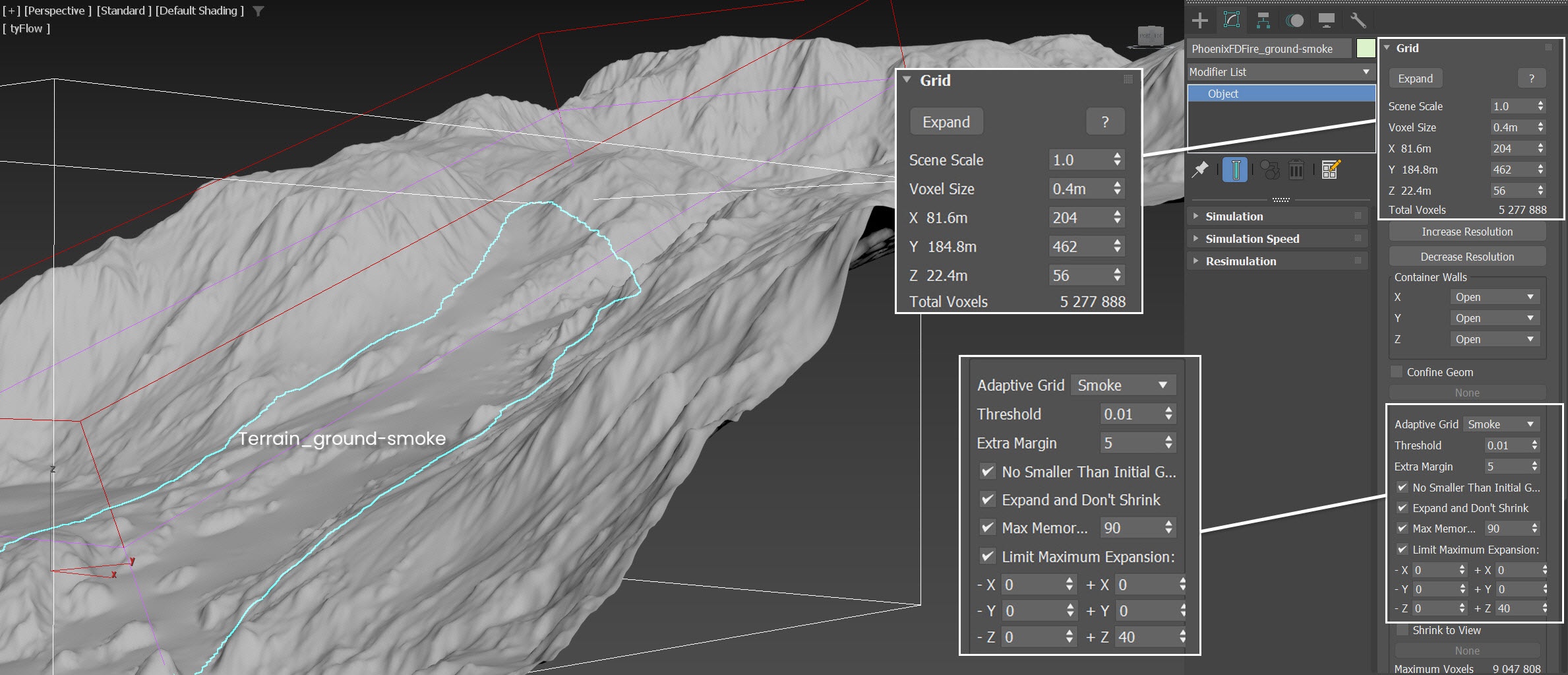
Open the Grid rollout and set the following values:
- Voxel Size: 0.4m;
- Size XYZ: [ 204, 462, 56 ] - We keep the simulator size small enough to roughly cover the region of Terrain_ground-smoke;
- Adaptive Grid: Smoke - the Adaptive Grid algorithm allows the bounding box of the simulation to dynamically expand on-demand. With a Threshold of 0.01, the Simulator expands when the Voxels near the walls of the simulation bounding box reach a Smoke value of 0.01 or greater;
- Enable Expand and Don't Shrink - this way the Adaptive grid does not contract back when there is very thin smoke at the borders of the grid;
- Enable Max Expansion: X: (0, 0), Y: (0, 0), Z: (0, 40) - to save memory and simulation time by limiting the Maximum Size of the simulation grid.
The initial grid size of the PhoenixFDFire_ground-smoke roughly covers the region of Terrain_ground-smoke, which is a geometry duplicated partially from the Terrain geometry.
Since we don't require intricate details like an avalanche effect, we've assigned a Voxel Size of 0.4 to the Simulator. This provides enough grid resolution for the ground smoke.
We rotate the Simulator, and make it align (by 17°) with the Terrain geometry. By doing this, we save some simulation time due to the use of a smaller grid size.
Adding ground smoke to the scene also helps blending the avalanche with the ground terrain.
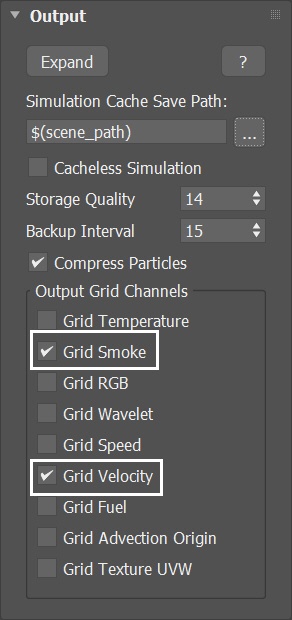
Select the Phoenix Simulator → Output rollout and enable the output of Grid Smoke and Grid Velocity Channel.
Any channel that you intend to use after the simulation is complete, needs to be cached to disk. For example:
Velocity is required at render time for Motion Blur;
Temperature is usually used at render time to generate Fire;
Wavelet is used for Wavelet turbulence when performing a Resimulation.
We don't need a resimulation of the ground smoke since it is meant to be thin and to enhance the visual impact of the avalanche. There's no need for extremely high detail in this smoke effect.
Adding a Fire/Smoke Source for the Ground Smoke
Create a Phoenix Fire/Smoke Source in the scene: Create Panel → Create → Helpers → PhoenixFD → PHXSource. Rename it to PHXSource_ground-smoke.
Press the Add button to choose which geometry to emit and select the Terrain_ground-smoke entry in the Scene Explorer.
The Terrain_ground-smoke geometry is derived from the base Terrain. Manually select and copy the faces corresponding to the valley within the terrain geometry, creating a duplicate that is then renamed to Terrain_ground-smoke.
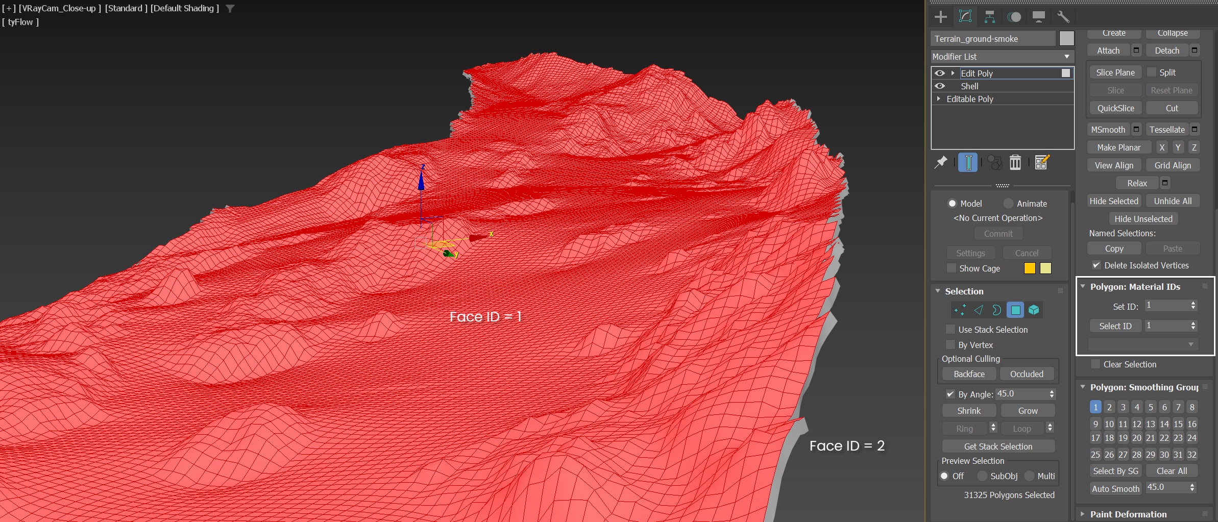
The Terrain_ground-smoke has Edit Poly and Shell modifiers applied.
The purpose of the Shell Modifier is to give the plane volume by turning it into an actual 3D shape with thickness. In order to get predictable simulation results using Phoenix it's best to use shelled, closed geometry.
Within the Edit Poly modifier, we specifically select the top side of the terrain and assign a face ID of 1, while the remaining faces are assigned a face ID of 2. This setup enables us to restrict fluid emission to only one side of the mesh.
As mentioned earlier, all the helper geometries, including the Terrain_ground-smoke, have their Object Properties configured to Display as Box, with the Renderable option disabled. Here, we temporarily display it as a mesh solely for the purpose of illustrating the idea of the face ID.
Set up the PHXSource_ground-smoke's properties:
Set the Emit Mode to Surface Force.
- Set the Outgoing Velocity to 5.0m.
- Set Noise to 0.5.
Disable the Temperature.
Set the Smoke to 1.3.
- Set both the Outgoing Velocity and Smoke's Mask type to Texmap.
Set the Polygon ID to 1. This limits the emission only to faces with an ID of 1.
Create a Noise map:
- Plug the map into both the Outgoing Velocity's Texmap slot and the Mask for Smoke slot.
- Rename it to Noise_for_ground-smoke.
- Set the Noise parameters:
Set the Noise Threshold High to 1.0, Low to 0.485.
Set Levels to 3.0.
Set the Size to 10.0.
Set the Noise type to Fractal.
- Animate the value for the X Offset.
We set the Outgoing Velocity to 5.0 m; otherwise, it will be too fast. The Noise is set to 0.5 for some randomness in the emission. Additionally, the Smoke amount is set to 1.3 to represent thin smoke, resembling blowing snow from the ground.
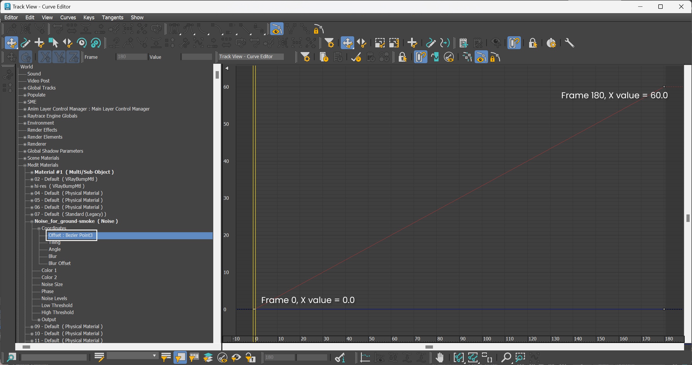
We apply a mask to the PHXSource_ground-smoke, ensuring that only certain parts of the Terrain_ground-smoke emit smoke. Further, to prevent the smoke from originating solely from the same spot, we animate the X Offset to introduce variation in the emission location. In addition to animating the X offset of the Noise map, you can also animate the Y or Z offset according to your preference.

Enable 3ds Max Auto Key Mode. Set the new tangent type keyframes to Linear. At frame 0, set the X Offset of Noise_for_ground-smoke to 0. At frame 180, set the X offset to 60.0.
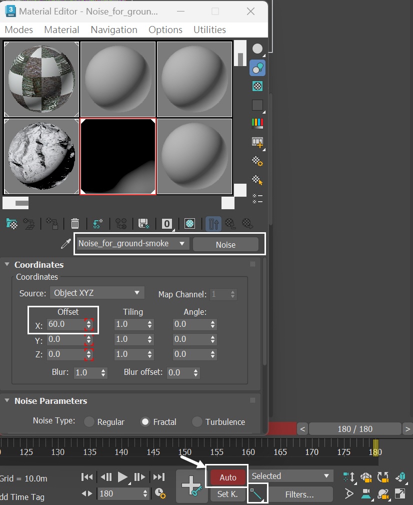
Enable 3ds Max Auto key frame. Set the new tangent type keyframes to Linear. At frame 0, set the X Offset of Noise_for_ground-smoke to 0. At frame 180, set the X offset to 60.0.
Go to Graph Editors/Track View → Curve Editor and find the keyframes of Offset for the Noise_for_ground-smoke.
Each frame and value used in this tutorial are shown in the screenshots.
Adding Plain Force
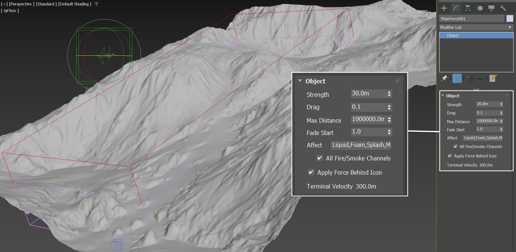
Create a Phoenix Plain Force , a simple directional force, to simulate the effect of wind.
Go to Create Panel > the Helpers tab > Phoenix and add a Phoenix Plain Force.
The exact Position of the Plain Force in the scene is: XYZ: [ 60.0, -23.0, 80.0 ].
Rotate the Plain Force to XYZ[97.0, 8.0, 28.0]. Set its Strength to 30.0m.
Enable the Apply Force Behind Icon option.
We set the Plane Force strength to 30.0 m for the wind to be strong enough to achieve our desired results.
We rotated the Plain Force so that it roughly points towards the camera. This way, the ground smoke blows in the direction of the camera.
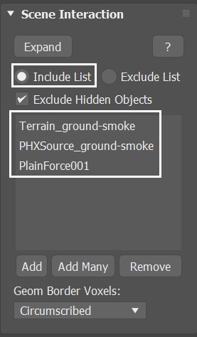
With the PhoenixFDFire_ground-smoke selected, navigate to the Scene Interaction rollout. Add PlainForce001 to the Include List.
With the new Plain Force and the PHXSource_ground-smoke in the scene, let's run the simulation again.
This is a voxel preview of the current animation.
Volumetric Shading for Shot 02 - the Ground Smoke
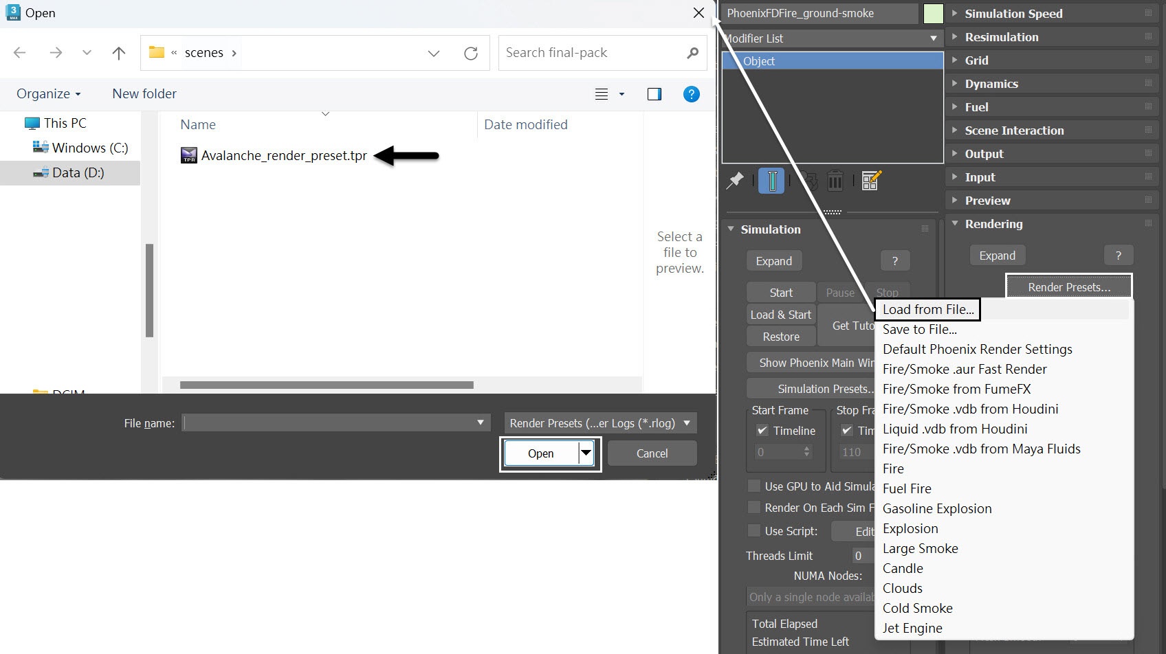
Again, PhoenixFDFire_ground-smoke in Shot02 shares the same Volumetric Shading setup as shot01, so there's no need to set it up from scratch. You can load up a render preset from the Avalanche_render_preset.tpr file, that is provided in the sample scene.
How can the ground smoke, which is supposed to be thin, and the avalanche smoke, which is thick, share the same volumetric settings? This is because the thickness of the smoke is controlled by the Smoke Amount setting within its respective Fire/Smoke Sources. Specifically, the Smoke Amount for PHXSource_ground-smoke is set to 1.3, while the Smoke Amount for PHXSource_avalanche is set to 3.0.
Create a Fog Fire/Smoke Simulator
In order to simulate the fog in the scene we can use a Fire/Smoke Simulator instead of a V-Ray Environment fog. This way we can avoid blending issues between the Phoenix Simulators and V-Ray Environment fog and skip using the slower Volumetric Geometry Mode for the rendering.
Let's create one now. Go to Create Panel > Create > Geometry > PhoenixFD > FireSmokeSim. Rename it to PhoenixFDFire_fog.
The exact position of the PhoenixFDFire_fog in the scene is: XYZ: [ 135.0, -2.6, 21.3 ].
The exact rotation of the PhoenixFDFire_fog in the scene is XYZ: [ 17.0, 0.0, 0.0 ].
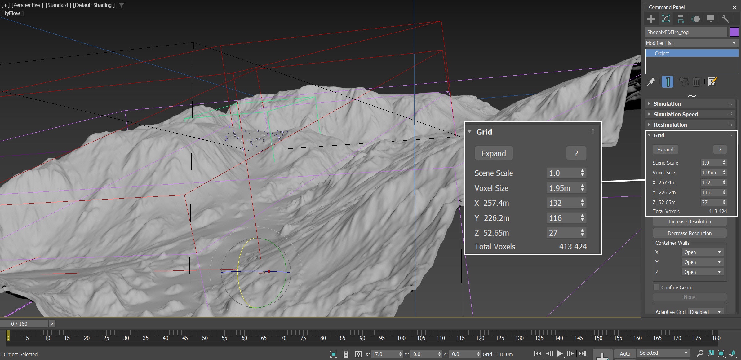
Open the Grid rollout and set the following values:
- Voxel Size: 1.95 m
- Size:
X: 132
Y: 116
Z: 27
We rotate the Simulator, making it align (by 17°) with the Terrain geometry.
Volumetric Shading for Shot 02 -Fog
Select the PhoenixFDFire_fog and go to its Volumetric Render Settings.
- Set the Fire Based on option to Disabled - we don't need any fire for the fog effect.
- Change the Smoke Color to pure white of RGB (255, 255, 255).
- Set the Scattering to Ray-traced.
- Disable the Volume Light Cache option.
- Set the Smoke Opacity Based on option to Smoke.
- In the Opacity diagram, adjust the Y value of the first curve point to 0.001. This way we can create a fog volume without actually running the simulation.
The larger the Y value of the first curve point is, the thicker the fog gets. Adjust its value according to your preference.
The Y value for the initial curve point of the Smoke Opacity in Shot 01 is 0.004, which is lower than the setting here for Shot 02. However, the final appearance of the environmental fog matches seamlessly, resulting in visual continuity between the two shots.

Now that we have all the elements necessary for shot 02, unhide ChaosScatter, Alembic_leaf, Alembic_snow, Alembic_stem, and all the Simulators in the scene. Let's run a final preview before rendering.
This is a voxel preview of the current animation.
To prevent the smoke voxels from obstructing the animated trees entirely in the preview, within the Preview rollout of PhoenixFDFire_ground-smoke, we set the Detail Reduction to 4.
To simplify your workflow when selecting objects within the Alembic group, access the dropdown menu in the Select by Name window. Navigate to Select and opt for Select Children. Enabling this option allows you to automatically select all child objects within the Alembic group when choosing Alembic_leaf, Alembic_snow, or Alembic_stem.
Render Elements
In the Render Setup > Render Elemets tab, add VRayLightMix render elements. This is necessary for relighting the scene in the VFB.
V-Ray Frame Buffer and Relighting with LightMix
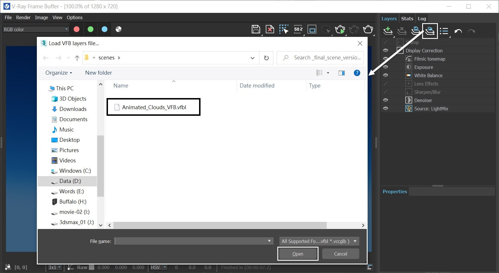
Shot02 shares the same color correction settings as shot01, so there's no need to set it up from scratch. In the V-Ray Frame Buffer, click Load Layer Tree Preset...
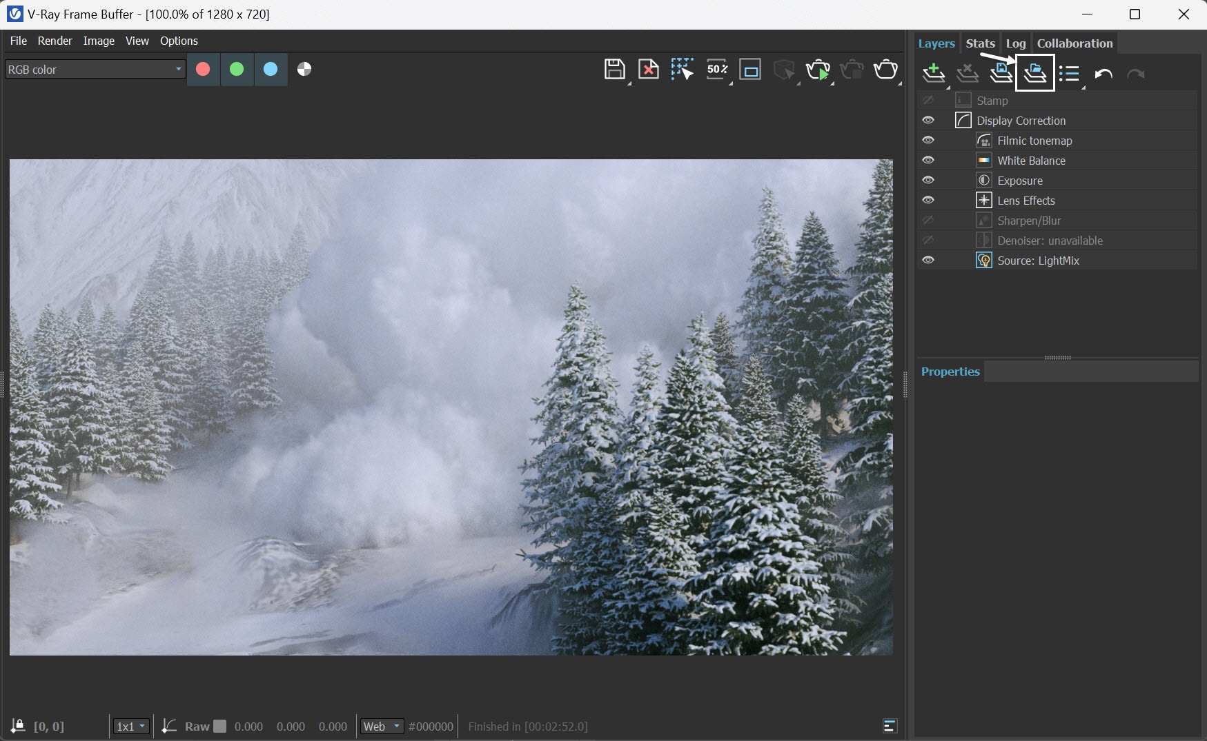
...and load the Avalanche_VFB.vfbl file that is provided in the sample scenes.
Here is the final rendered result (from frame 120 to frame 180) for Shot02 of the avalanche scene.
Final composite
We now have sequences of avalanche scenes for both the full shot and the close-up. You can utilize any editing software to produce the complete animation.