This page offers information about the V-Ray Car Paint 2 material in Cinema 4D.
Overview
VRayCarPaint2 is a material that simulates a metallic car paint. It is a complex material with three layers: a base diffuse layer, a flake layer, and clear coat layer. The material allows the adjustment of each of these layers separately. The new VRayCarPaint2 uses GGX BRDF type and offers base glossiness tail falloff option.
UI Paths
||V-Ray|| > VRayCarPaint2
||Create|| > V-Ray > VRayCarPaint2 (disabled Separate menu for V-Ray materials)
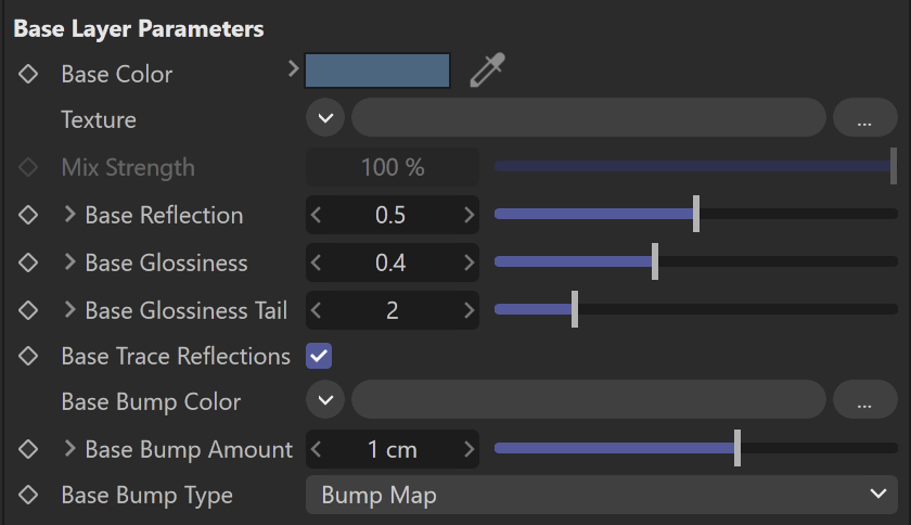
Base Layer Paramaters
Base color – Specifies the diffuse color or map for the base layer.
Base Reflection – Specifies reflectivity value or map for the base layer. The reflection color itself is the same as the Base color.
Base Glossiness – Specifies reflection glossiness value or map for the base layer. Higher values such as the default make the highlights sharper, while lower values make the transition more subtle.
Base Glossiness Tail – Controls the transition from highlighted areas to non-highlighted areas. Higher values such as the default make the highlight transition sharper and lower values make the glossiness tail more diffuse.
Base Trace Reflections – When disabled, the base layer only produces specular highlights, but no (glossy) reflections.
Flake Layer Paramaters
Flake Color – Specifies the color or map of the metal flakes.
Flake Orientation – Specifies the orientation value or map of the metal flakes. The orientation of the flakes is relative to the surface normal. When set to 0.0, all flakes are perfectly aligned with the surface. When set to 1.0, the flakes are rotated completely randomly with respect to the normal. Values above 0.5 are not recommended as they can produce artifacts.
Flake Density – Specifies the density (number of flakes) for a certain area. Lower values produce less flakes and higher values produce more flakes. Set this to 0.0 to produce a material without flakes.
Flake Scale – Scales the entire flake structure.
Flake Size – Specifies the size of the flakes relative to the distance between them. Higher values produce bigger flakes and lower values produce smaller flakes.
Flake Map Size – Internally the material creates several bitmaps to store the generated flakes. This parameter determines the size of the bitmaps. Lower values reduce RAM usage, but may produce noticeable tiling in the flake structure. Higher values require more RAM, but tiling is reduced.
Flake Seed – The random seed for the flakes. Changing this produces different flake patterns.
Mapping Type – Specifies the method for mapping the flakes.
Mapping channel – The flakes are mapped using the specified channel.
Triplanar – The material automatically computes mapping coordinates in object space based on the surface normals.
Flake Trace Reflections – When disabled, the flakes only produce specular highlights, but no actual reflections are traced.
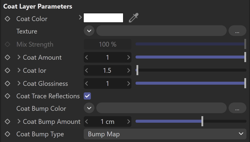
Coat Layer
Coat Color – Specifies the color or map of the coat layer.
Coat Amount – Specifies the thickness amount of the coat layer. A value of 0 does not add a coat layer, while higher values blend the coat gradually.
Coat Ior – Specifies the Index of Refraction for the coat layer.
Coat Glossiness – Specifies the glossiness value or map of the coat reflections.
Coat Trace Reflections – When disabled, the clear coat will only produce specular highlights, but no actual reflections.
Coat Bump Type –
Options
Material Id Enabled – Enables the use of Material ID.
Material ID – The color used by the "Material ID" render element. You can also use a shader here.
Multimatte ID – The integer ID of the material to be used by the "Multimatte" render element.
Round Edges Enabled – Enables the round edges effect which uses bump mapping to smooth out the edges of the geometry during render time.
Radius – Specify a radius (in world units) for the round edges effect. Since the actual geometry is not being changed and only the normals of the faces are affected, large values here may produce undesirable effects.
Consider Same Object Only – When enabled, the rounded corners are produced only along edges that belong to the same object which has the attribute applied. When disabled, rounded corners are produced along edges formed when the object with the attribute intersects other objects in the scene.
Corners – Choose which edges are considered in the calculation. Possible options are:
Covex and Concave – Considers all edges.
Convex Only – Only applies Round Edges effect to edges with convex angles.
Concave Only – Only applies Round Edges effect to edges with concave angles.
Trace Reflections – When disabled, reflections from the different layers are not traced (they will only produce specular highlights).
Trace Depth – Allows the user to control the maximum number of times a ray is going to be reflected by the material.
Double Sided – When enabled, the material is double-sided.
Cutoff Threshold – Specifies the cutoff threshold for the reflections of the different layers.

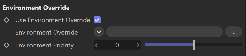
Environment Override
Use Environment Override – Enabled environment override.
Environment Override – Specifies the Environment override texture for this material.
Environment Priority – Specifies the priority of the material.