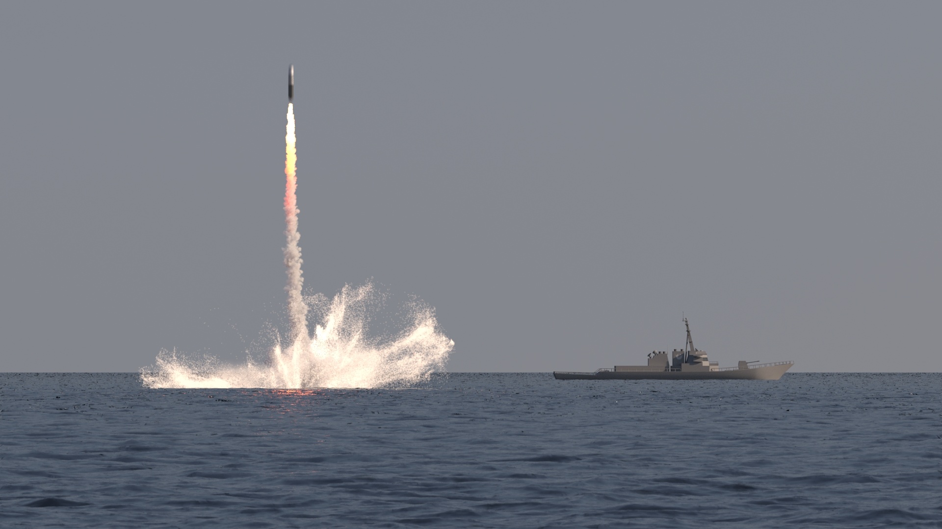
This page guides you through the process of creating a submarine-launched ballistic missile (or SLBM) using Chaos Phoenix 4.4 and V-Ray 5.
Overview
This Advanced Level tutorial shows you how to create an underwater ballistic missile launch using Phoenix. Note that creating a production quality shot may require some tweaks to lighting, materials and/or the Phoenix simulation.
The final shot we aim at involves not just water, but also Fire and Smoke. A particle flow (PFlow) system is used as a source for the missile smoke trail. The smoke is simulated using Phoenix Fire/Smoke simulator.
For the liquid, we add three Liquid sources to achieve the effect. One is linked to the missile, one to the Geosphere, and the third to the Cone geometry that emits splash particles. The liquid and the particles are simulated with a Phoenix Liquid Simulator. Together all these compose a convincing submarine-launched ballistic missile effect.
This simulation requires Phoenix 4.4 Build and V-Ray 5 Official Release for 3ds Max 2017 at least. If you notice a major difference between the results shown here and the behavior of your setup, please send an email to support@chaosgroup.com.
The Download button below provides you with an archive containing the scene files.
(Please replace this image with SLBM_final.mp4)
Units Setup
Scale is crucial for the behavior of any simulation. The real-world size of the Simulator in units is important for the simulation dynamics.
Large scale simulations appear to move slower, while mid-to-small scale simulations have lots of vigorous movements.
When you create your Simulator, check the Grid rollout where the real-world sizes of the Simulator are shown. If the size of the Simulator in the scene cannot be changed, you can trick the solver into working as if the scale is larger or smaller by changing the Scene Scale option in the Grid rollout.
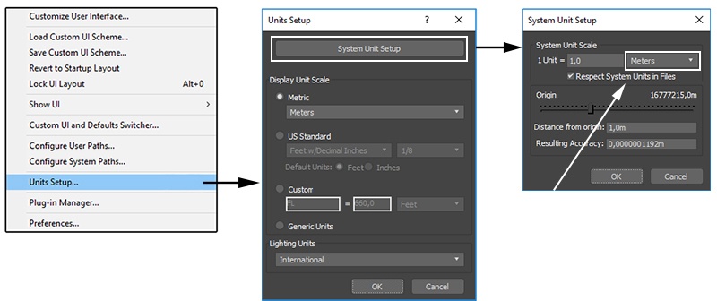
The Phoenix solver is not affected by how you choose to view the Display Unit Scale - it is just a matter of convenience. Setting the units to Meters is a reasonable choice.
Go to Customize → Units Setup and set Display Unit Scale to Metric Meters. Also, set the System Units so that 1 Unit equals 1 Meter.
Scene Layout
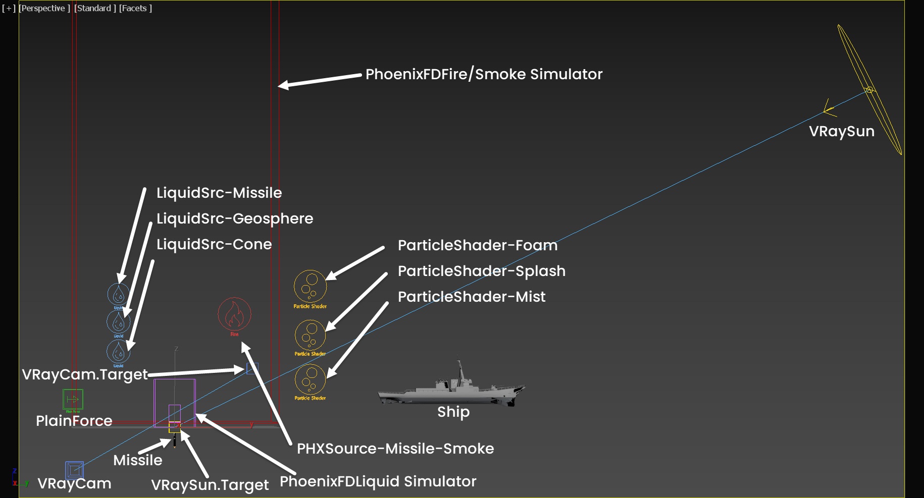
The final scene contains the following elements:
- Ship object for creating a sense of scale in the scene;
- Missile geometry;
- Three Liquid sources, each using the Missile, GeoSphere and Cone as emitters, respectively;
- Phoenix Fire / Smoke source for smoke trail;
- Phoenix Plain Force as a wind force in the scene;
- Phoenix Fire/Smoke Simulator;
- Phoenix Liquid Simulator;
- V-Ray Physical Camera (VRayCam)for rendering;
- V-Ray Sun & Sky setup for lighting.
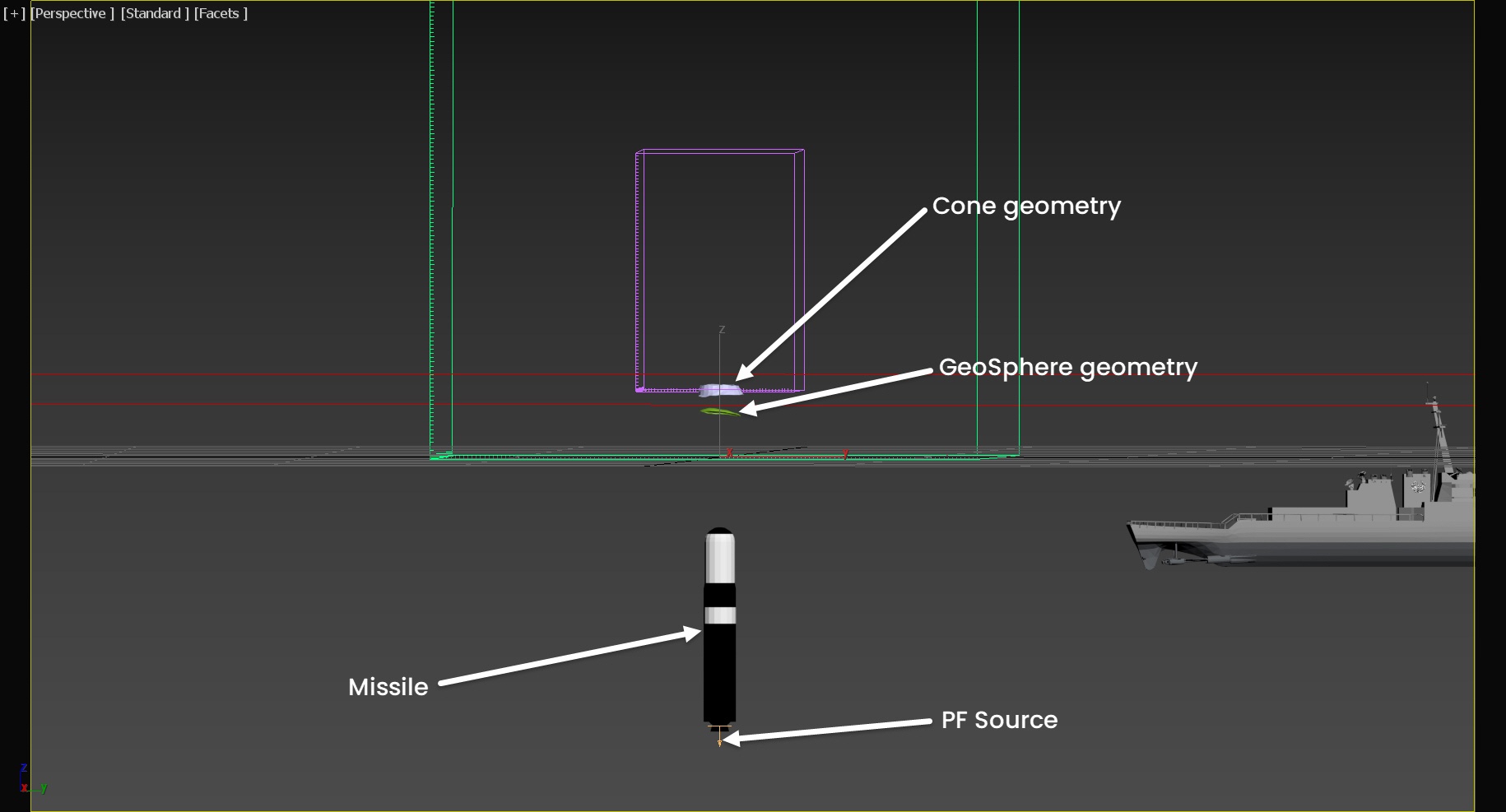
A close-up for the final scene contains the following elements:
- Cone geometry as a liquid source;
- GeoSphere geometry as another liquid source;
- Missile object;
- Particle Flow node: PF Source that is linked to the moving missile object.
Scene Setup
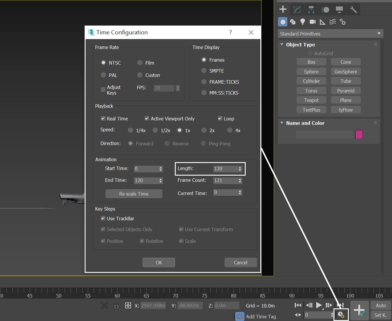
Set the Time Configuration → Animation Length to 120 so that the Time Slider goes from 0 to 120.
This tutorial involves both Fire, Smoke and Liquid simulations, and the steps are rather complicated. This tutorial will focus only on the Phoenix-related steps. Feel free to use the camera and light settings in the provided sample scene.
For reference, below you can find the camera and light settings.
Camera Settings
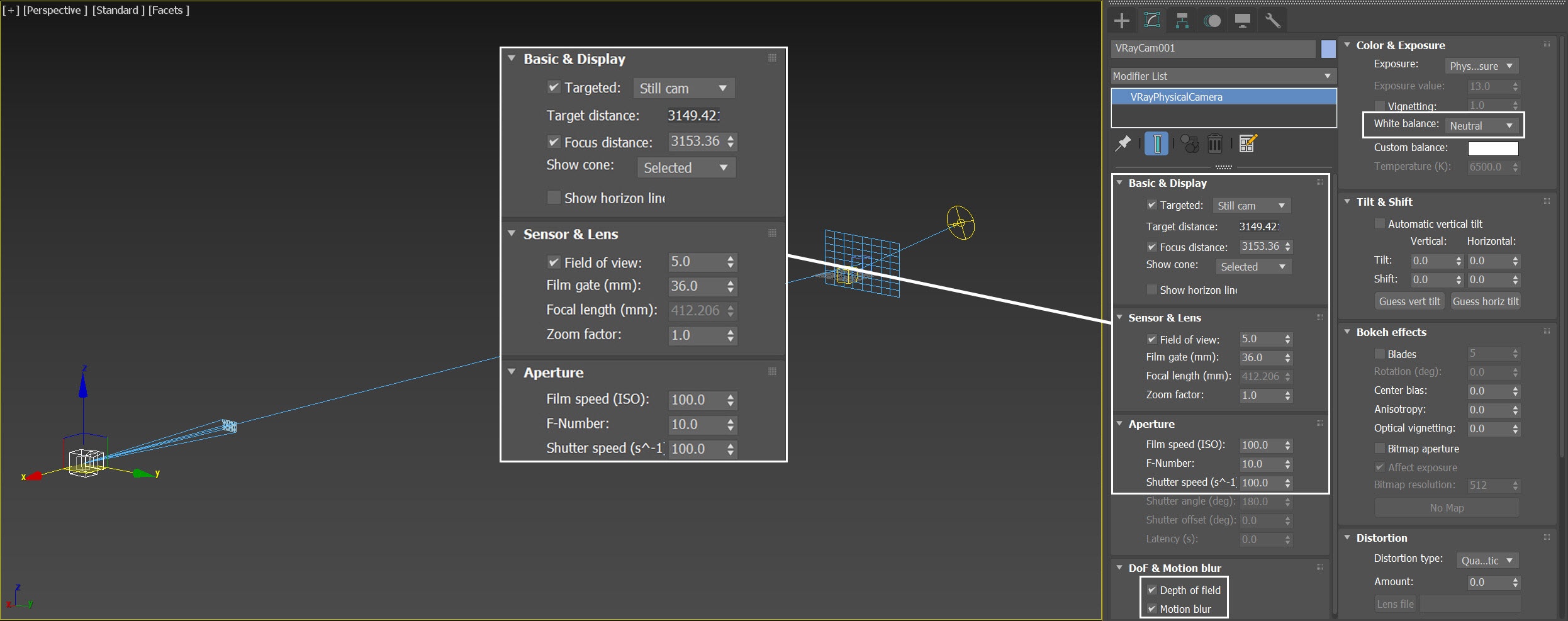
From Create Panel → Cameras → V-Ray → VRayPhysicalCamera, add a camera
The exact position of the Camera is XYZ: [ 3147.05, -134.6, 7.95 ]
The exact position of the Camera Target is XYZ: [ 3.35, 52.5, 39.5 ]
Sensor & Lens → Field of view is enabled and set it to 5.0
Sensor & Lens → Film gate is set to 36.0
Aperture → Film speed is set to 100.0
Aperture → F-Number is set to 10.0
Aperture → Shutter Speed is set to 100
Both Depth of field and Motion Blur are Enabled.
Color & Exposure → White Balance is set to Neutral.
We set this camera a super tele lens giving it a sense of distance from the missile launch.
Lighting
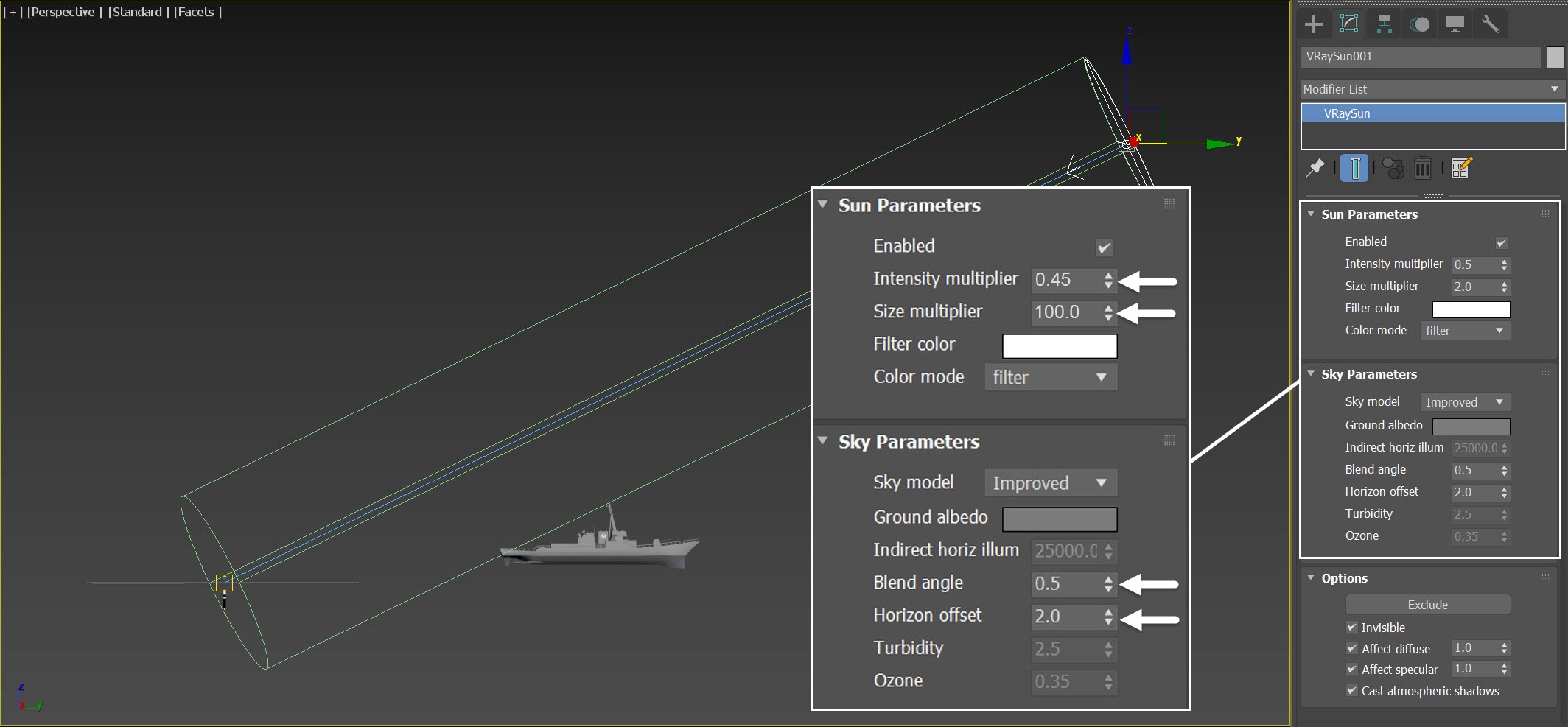
From Create Panel → Lights → V-Ray → VRaySun, create a VRaySun in the scene.
The exact position of the VRaySun is XYZ: [ 87.3, 462.5, 226.5 ]
The exact position of the VRaySun Target is XYZ: [0.0, 0.0, 0.0 ]
Decrease the Intensity multiplier to 0.5
Increase the Size multiplier to 2.0
Anatomy of the SLBM
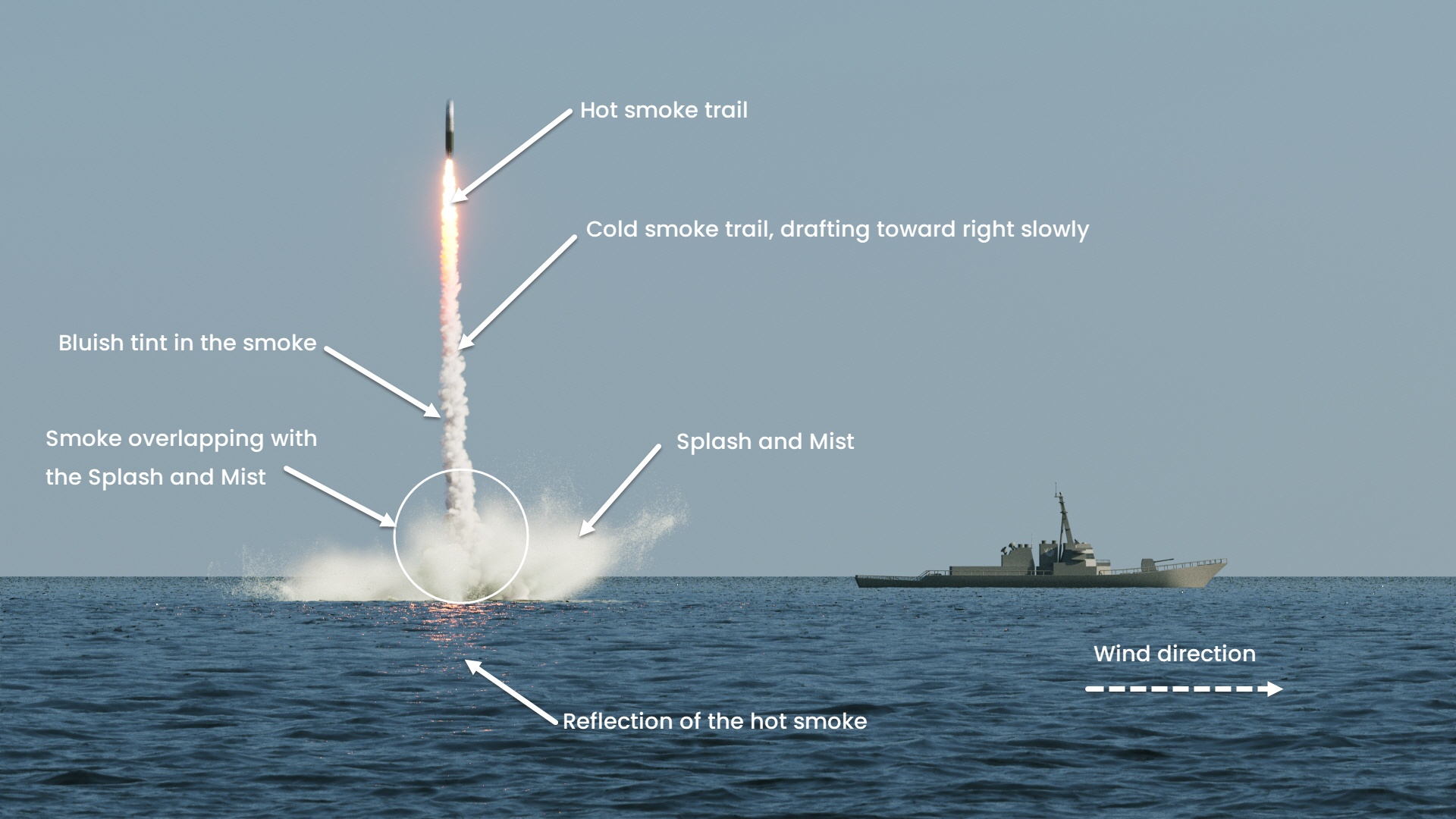
The shot requires several key features:
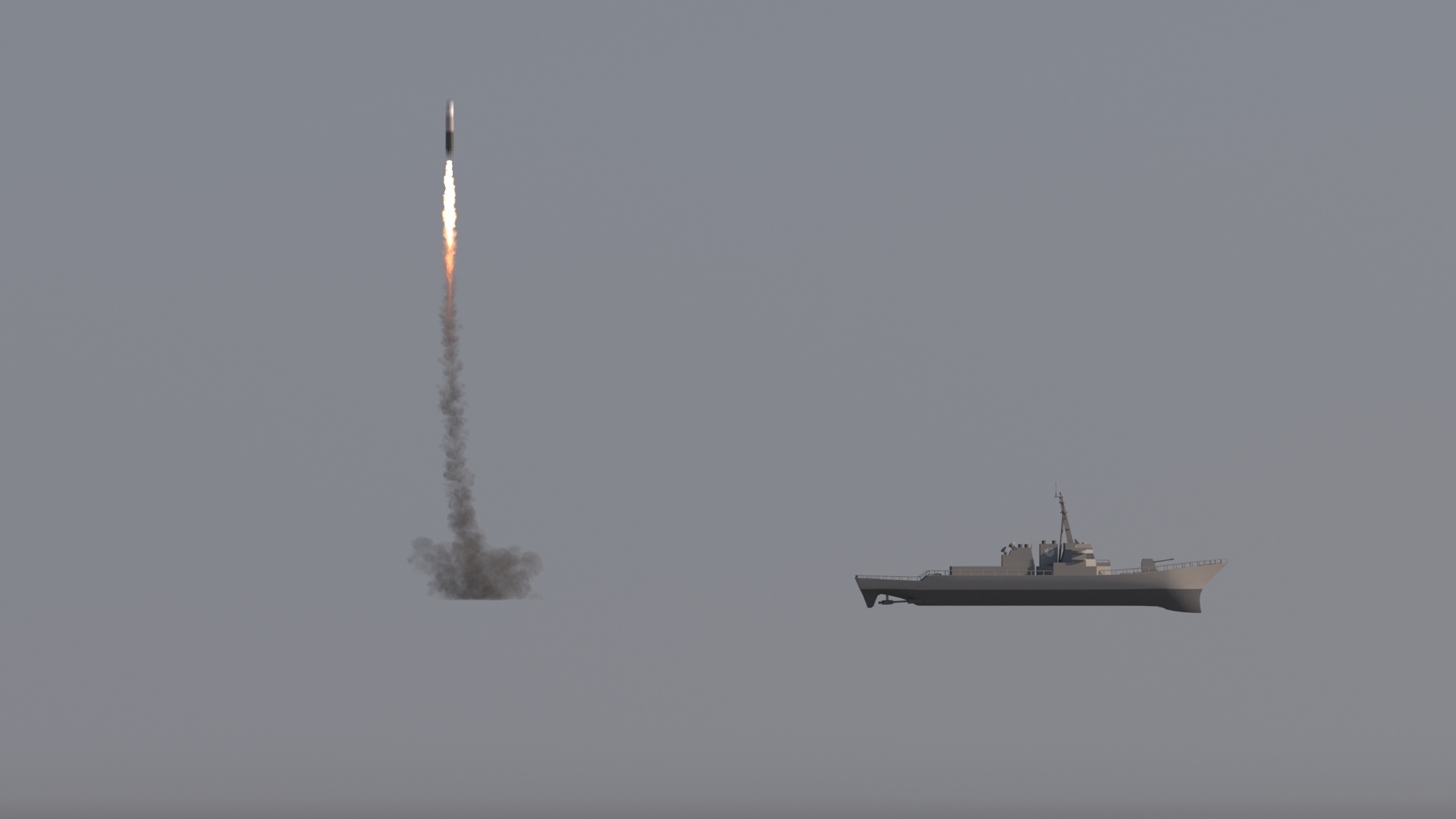
- The first item is when the rocket launches from underwater, the smoke trail drifts from left to right because of the wind. The direction of the ocean wave matches the plain force orientation in the scene.
- Secondly, once the missile launches, a large number of splashes comes out of the sea. The smoke trail is bright white with a bluish tint. We can see a reflection of the hot smoke on the ocean surface, even though the rocket is flying out of the camera. Meaning the Fire / Smoke simulator must be tall enough for an out of camera frustum.
Though the smoke and liquid are simulated independently, parts of the splash/mist /foam overlap with the smoke, making the shot visually more convincing.
Timeline of the SLBM animation
Here are the general stages of the SLBM shot:
- The missile launch at frame 5, it gradually loses speed because of gravity.
- At frame 50, the missile starts to ignite. You can see hot, white smoke coming out of the missile nozzle while it is changing its trajectory.
- At frame 59, the missile ignition fire reaches the ocean surface, creating lots of water splashes.
- At frame 65, the missile enters the acceleration stage, rushing to the sky at full speed.
Particle Flow Settings
This section contains information about the Particle Flow settings. It is only provided as a starting point for the Phoenix Simulation.
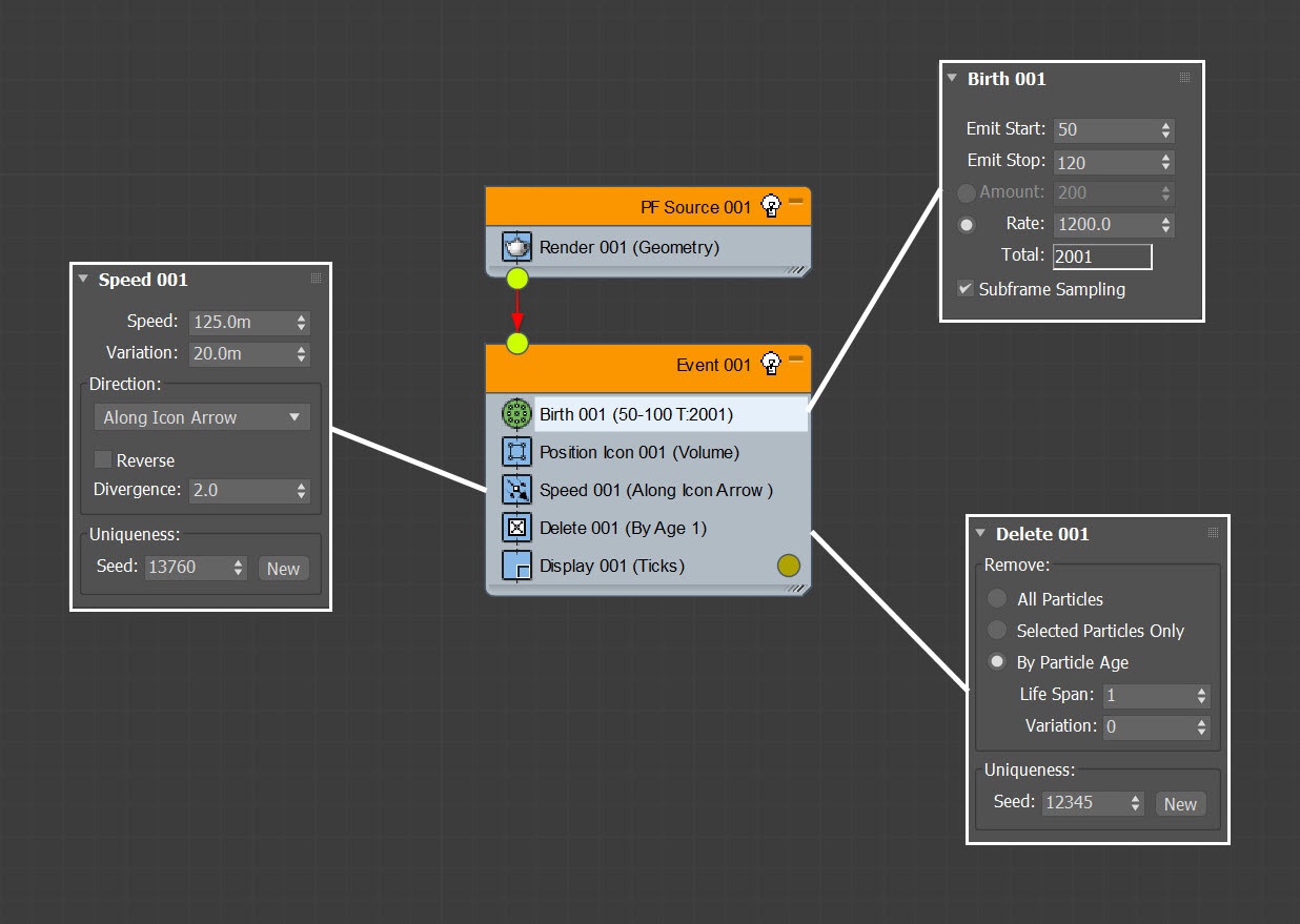
Here is a preview animation of the particle simulation. This particle system is very straightforward, there is only one event in the system. It is linked to the keyframed missile object.
Particles are shown in dark yellow color.
(Please replace this image with SLBM_PF.mp4)
Here is a Particle View of the particle systems. For the Birth operator, the Emit Start is set to 50 because the missile is ignited at frame 50.
The Speed for the particles are set to 120.0 m, with variation set to 20.0m.
The particle age is controlled with the Delete operator, with a Life span set to 1, so the particles won't last long.
The Divergence in the Speed operator affects the shape of the smoke trail. If the value is higher, it will spray particles wider, making a wider smoke trail.
Fire / Smoke Simulation
Go to Create Panel → Create → Geometry → PhoenixFD → FireSmokeSim.
The exact position of the Phoenix Simulator in the scene is XYZ: [ 0.0, 0.0, 3.25 ]
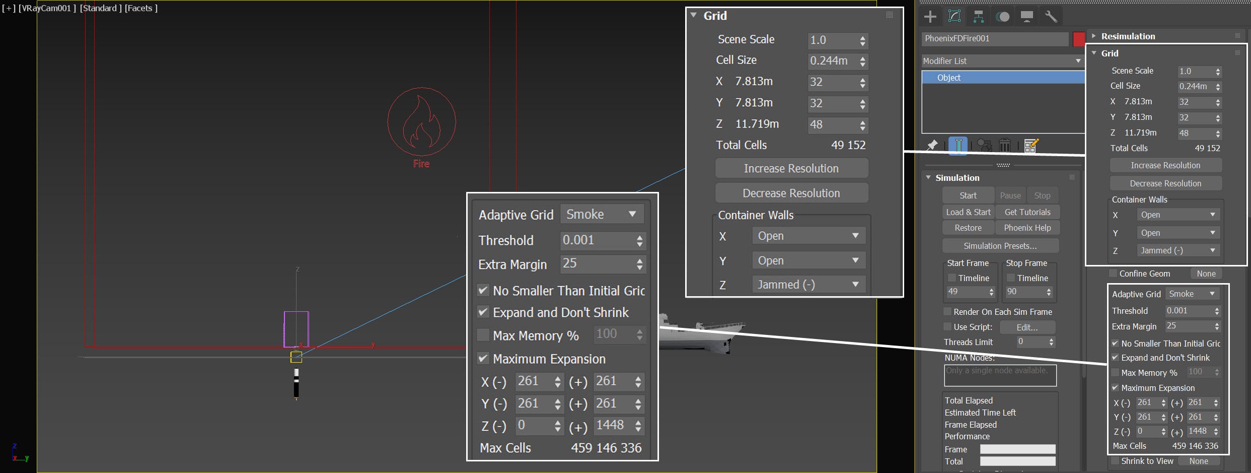
Open the Grid rollout and set the following values:
- Cell Size: 0.244 m
- Size XYZ: [ 32, 32, 48 ] - keep the Simulator size small to roughly cover the PFlow particles.
- Container Walls: Open to X and Y, but Jammed(-) to Z.
- Adaptive Grid: Smoke - the Adaptive Grid algorithm allows the bounding box of the simulation to dynamically expand on-demand. With a Threshold of 0.001, the Simulator expands when the Cells near the corners of the simulation bounding box reach a Smoke value of 0.001 or greater; Extra Margin to 25.
- Enable Expand and Don't Shrink - this way the Adaptive grid does not contract back when there is very thin smoke at the borders of the grid.
- Enable Max Expansion: X: (261, 261), Y: (261, 261), Z: (0, 1448) - save memory and simulation time by limiting the Maximum Size of the simulation grid.
The Fire / Smoke Simulator is positioned on the z-axis, according to the Liquid Simulator (that we will create in later steps) and its ocean level. The container walls are set to jam to Z (-), so later when we simulate the liquid, the missile trail smoke will appear colliding with the ocean surface.
The Max Expansion of the z-axis is set to an extremely high value. This is to make sure that the reflection of the smoke trail is long enough to reflect on the ocean surface. Otherwise, it won't look realistic when the smoke trail disappears while the missile flies out of camera view.
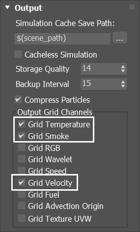
Select the Simulator → Output rollout and enable the output of Temperature, Smoke, and Velocity Grid Channel.
If you'd like to perform a Resimulation using Wavelet Turbulence for increasing the simulation detail, enable the Wavelet Grid Channel output.
Any channel that you intend to use after the simulation is complete needs to be cached to the disk. For example:
- Velocity is required at render time for Motion Blur;
- Temperature is usually used at render time to generate Fire;
- Wavelet is used for Wavelet turbulence when performing a Resimulation.
Adding Missile-Smoke Fire/Smoke Source
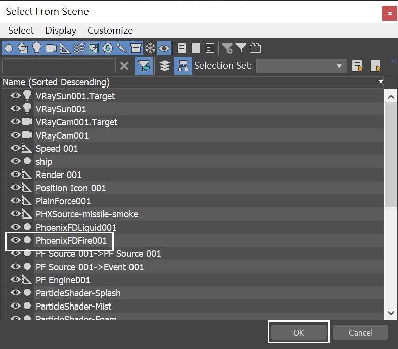
Create a Phoenix Fire/Smoke Source in the scene: Create Panel → Create → Helpers → PhoenixFD → PHXSource. Rename it to PHXSource-Missile-Smoke.
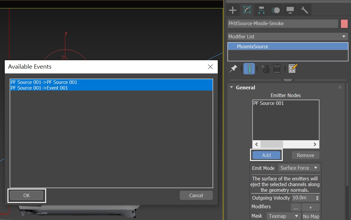
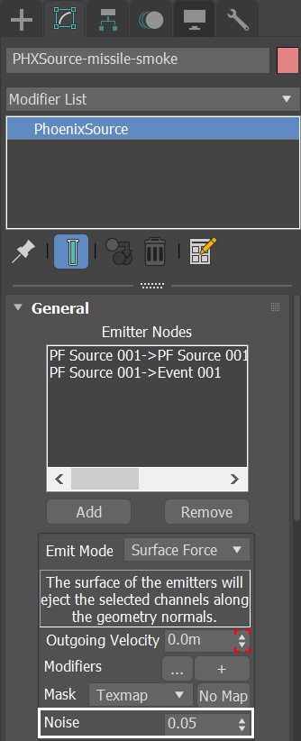
Press the Add button to choose which geometry to emit and select the PF Source entry in the Scene Explorer.
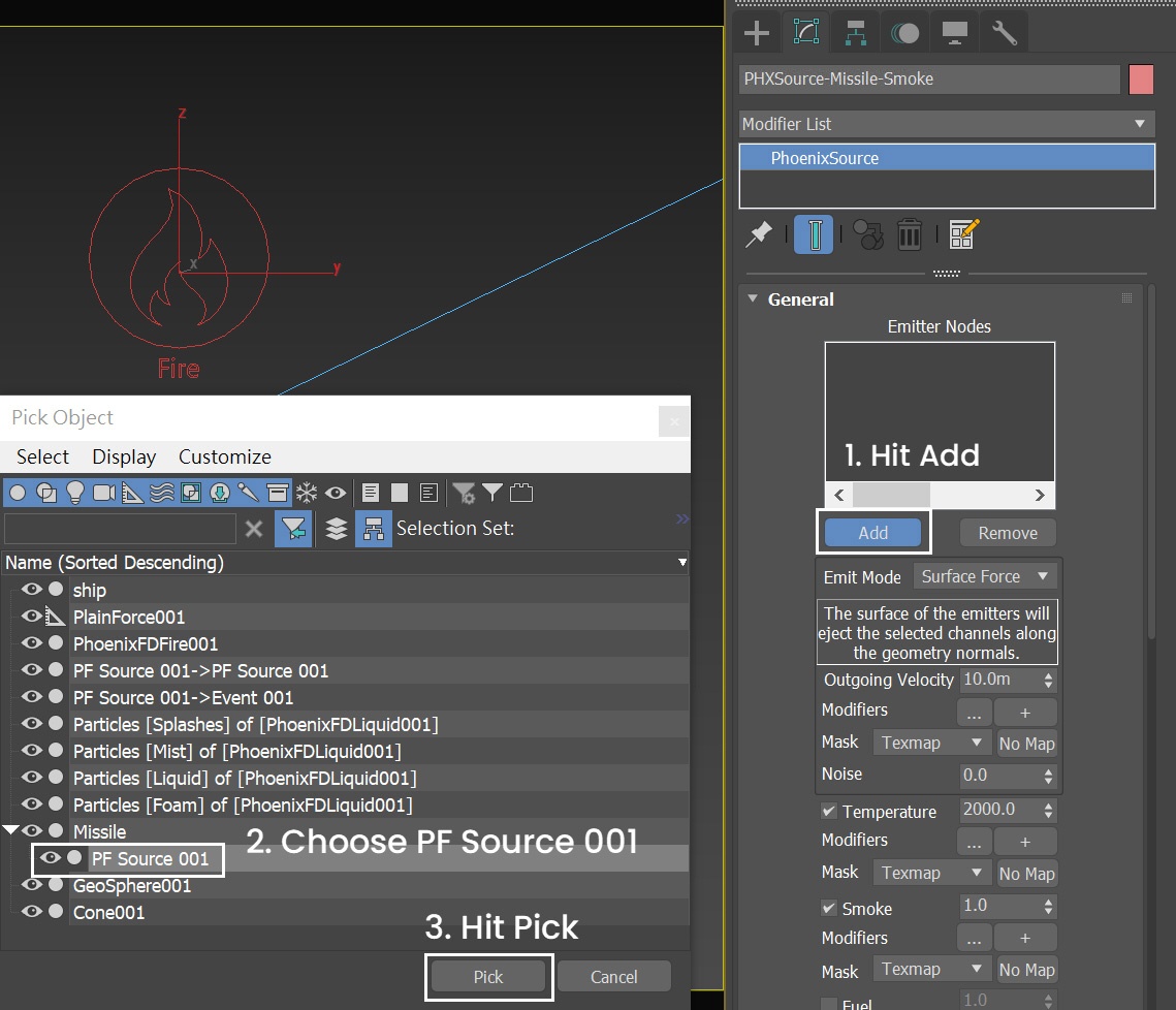
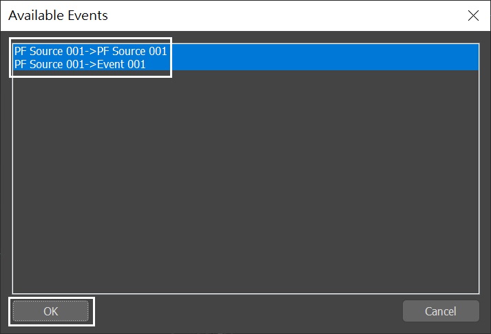
When you pick the PF Source node, the Available Events dialog pops out. Choose both the "PF Source 001→PF Source 001" and "PF Source 001→Event 001".
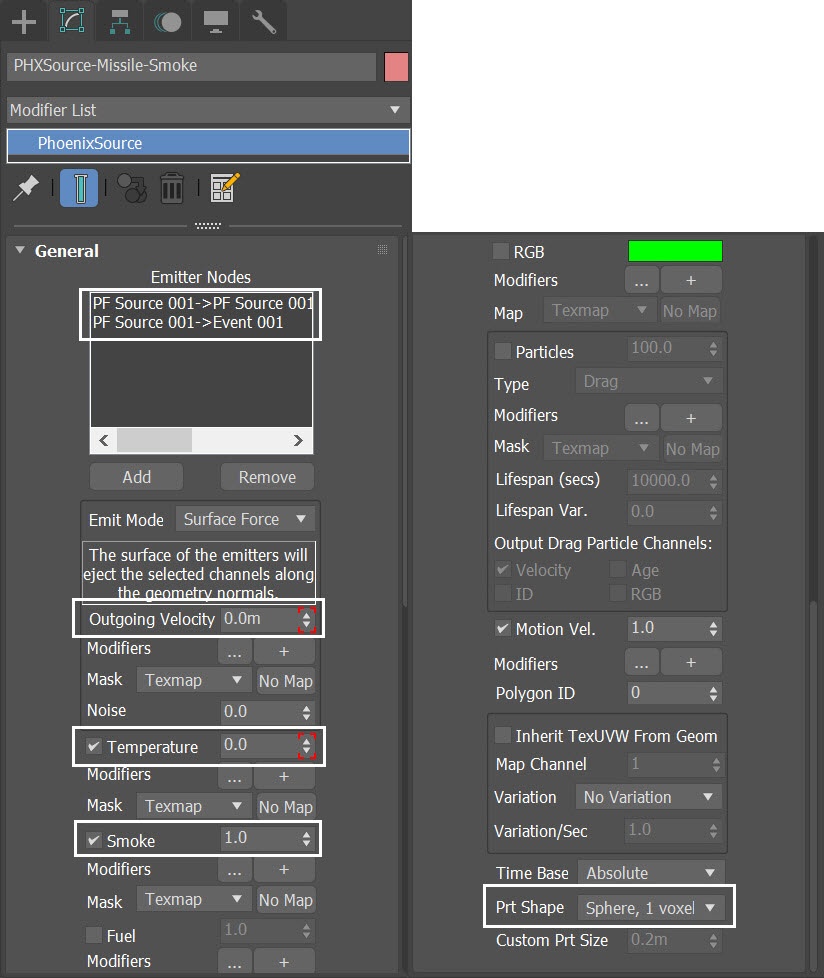
For the PHXSource-Missile-Smoke:
- Set the Emit Mode to Surface Force and animate its value.
- Animate the value of the Temperature.
- Set the Smoke to 1.0
- Set Motion Vel. to 1.0
- Prt Shape to Sphere, 1 voxel.
Go to Graph Editors/Track View → Curve Editor and set keys to the curve of PHXSource-Missile-Smoke's Outgoing Velocity. Set keyframes to Outgoing Velocity, so it can change over time.
Each frame and value are shown in the screenshots.
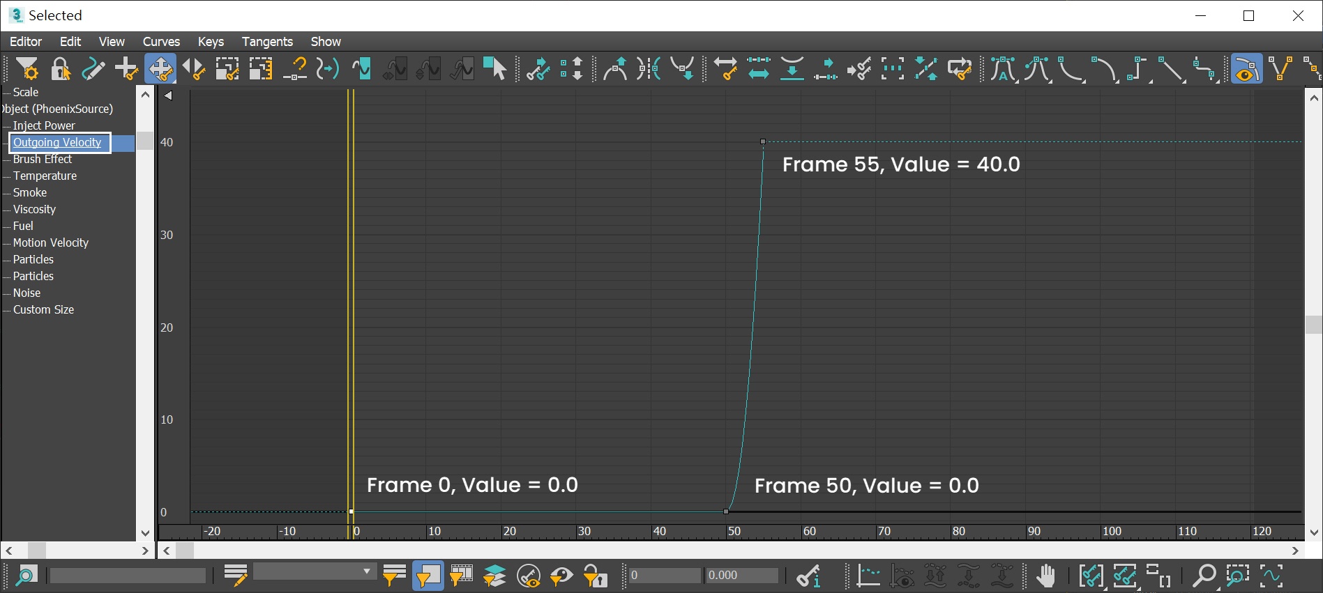
Here is the table for the keyframes of PHXSource-Missile-Smoke's Outgoing Velocity.
Frame | Value | Tangent type |
|---|---|---|
0 | 0.0 | Stepped |
50 | 0.0 | Slow |
55 | 40.0 | Fast |
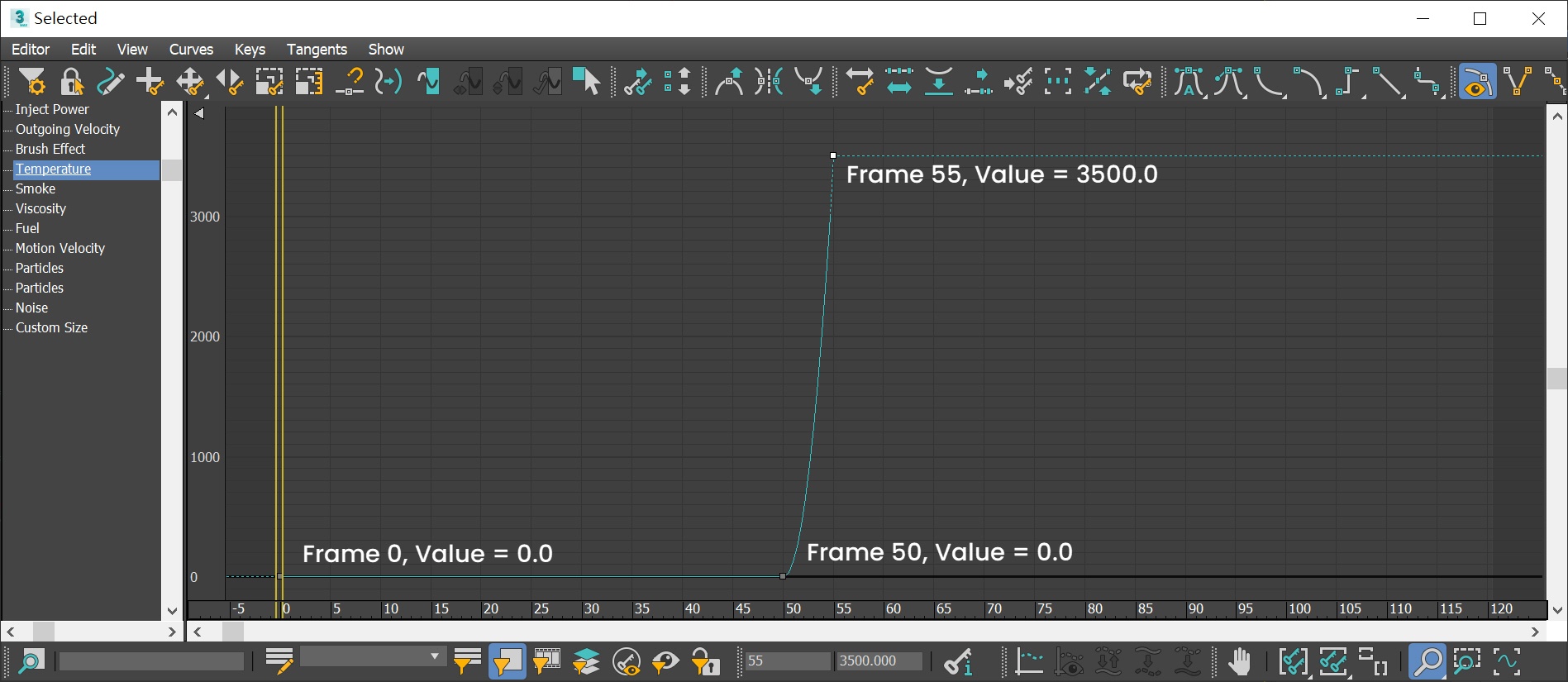
Go to Graph Editors/Track View → Curve Editor and set keys to the curve of PHXSource-Missile-Smoke's Temperature. We set keyframes to Temperature, so it can change over time.
Each frame and value are shown in the screenshots.
Phoenix animates the Temperature value, making the fiery smoke heat up gradually. This makes the ignition process more realistic.
Here is the table for the keyframes of PHXSource-Missile-Smoke's Temperature.
Frame | Value | Tangent type |
|---|---|---|
0 | 0.0 | Stepped |
50 | 0.0 | Slow |
55 | 3500.0 | Fast |
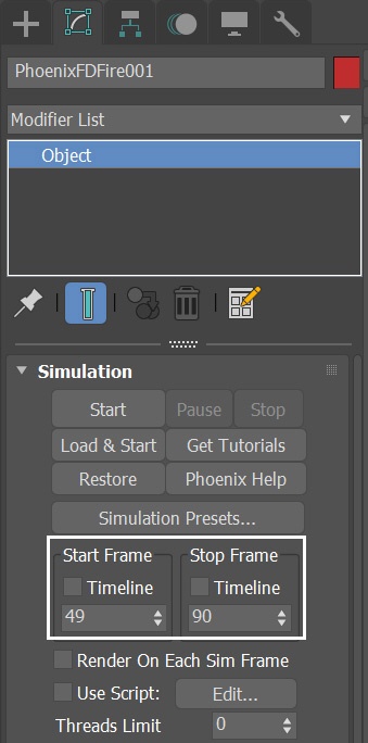
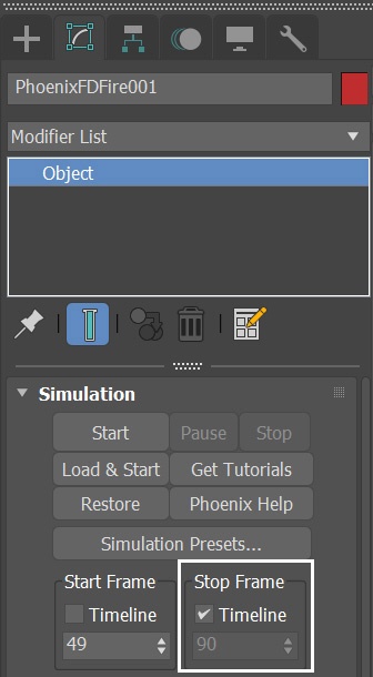
Select the Phoenix Fire / Smoke Simulator → Simulation rollout. Because the smoke animation started at frame 50, set the Start Frame to 49. You don't have to simulate the full length of the animation. Only a sample is needed, so set the Simulation rollout → Stop Frame to 90.
Press the Start button to simulate.
Here is a preview of the simulation up to this step. To improve the fluid simulation, switch the conservation method to PCG Symmetric in the next step.
To enable the GPU Preview, select the Simulator → Preview rollout → GPU Preview → Enable in Viewport.
(Please replace this image with SLBM_Step01.mp4)
Switch to PCG Solver
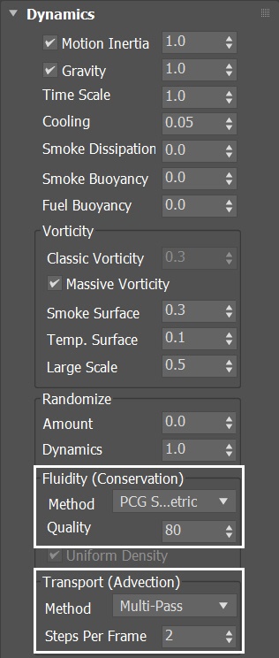
Select the Phoenix Fire / Smoke Simulator and change the Conservation Method to PCG Symmetric, with a Quality of 80. The PCG Symmetric option is the best method to use for smoke or explosions in general, preserving both detail and symmetry. The high Conservation Quality allows the smoke to swirl better. For in-depth information, check the Conservation documentation.
Here is a preview animation of the simulation up to this step.
(Please replace this image with SLBM_Step02-PCG.mp4)
Cooling
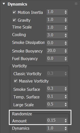
Now the smoke swirls better, but it stays hot for too long. Select the Phoenix Fire/Smoke Simulator, go to the Dynamics rollout. Increase the Cooling to 0.3.
With the new dynamics settings, run the simulation again.

Now the hot smoke cooled faster. The short tail of the hot smoke combined with the long streak of cool smoke, makes it more convincing.
(Please replace this image with SLBM_Step03-Cooling.mp4)
Adjusting Smoke Buoyancy
To make the smoke float up faster, select the Fire / Smoke Simulator, go to the Dynamics rollout, set the Smoke Buoyancy to 20.0. With the new Dynamics settings, run the simulation again.

This example shows the scene after adjusting Buoyancy.
(Please replace this image with SLBM_Step04-Buoyancy.mp4)
Adding Plain Force
For additional realism to the simulation, we use a Phoenix Plain Force to simulate the effect of wind.
Go to Create Panel → the Helpers tab → Phoenix and add a Phoenix Plain Force. It is a simple directional force.
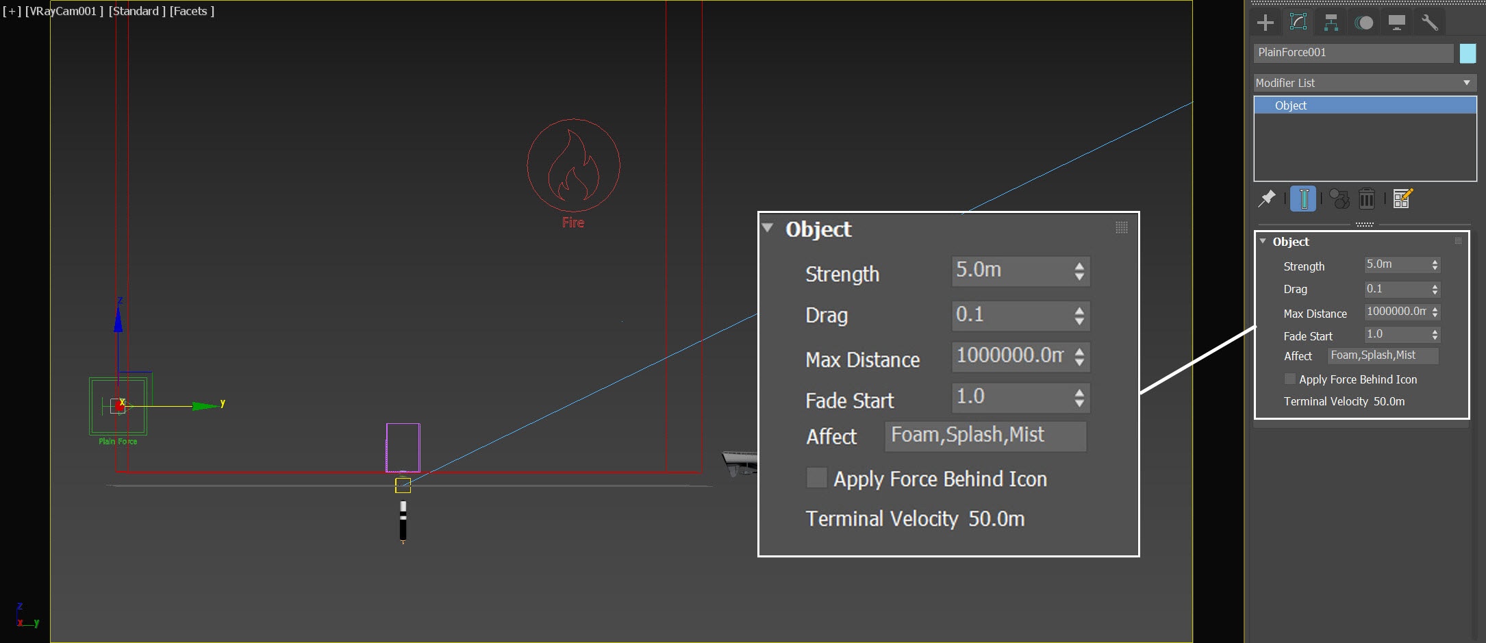
The exact Position of the Plain Force in the scene is XYZ: [23.0, -69.0, 19.0 ]
Rotate it so that it points in the minus X direction and set the Strength to 5.0 m. Set the Drag to 0.1. Enable the Apply Force Behind Icon option.
The exact Rotation of the Plain Force in the scene is XYZ: [-90.0, 0.0, 0.0 ]
Remove Liquid in the Affect list, because in later steps, that will cause it to blow on the ocean surface. The ocean liquid will be controlled purely by displacement.
When enabling the Apply Force Behind Icon option, the force is applied behind the helper icon. If disabled, the fluid behind the icon is not affected by Plain Force.
Up-res grid resolution
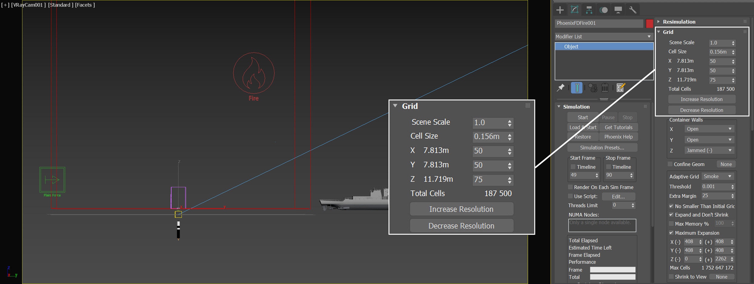
In order to get a more detailed result we also increase the Grid Resolution by lowering the Cell Size for the final simulation.
Open the Grid rollout and set the following values:
- Cell Size: 0.156 m
- Size XYZ: [ 50, 50, 75]
Press the Start button to run the simulation.
As you can see in this example, the smoke is slowly drifting toward the right.
(Please replace this image with SLBM_Step05-Wind.mp4)
Adding noise to the Missile-Smoke Fire / Smoke source
Let's give the PHXSource_Missile_Smoke some randomness. Set it's Noise to 0.05.
Run the simulation again.
This is what it looks like.
(Please replace this image with SLBM_Step06-Src-Noise.mp4)
Randomize the Dynamics
With the Fire / Smoke Simulator selected, go to the Dynamics rollout. Set the Randomize Amount to 0.4. The Randomize options add random fluctuations in the fluid's velocity for each grid voxel. This should reduce the smoke trail's volume, producing interesting disorder.
To simulate the full length of the animation, go to the Simulation rollout → enable the Timeline option for the Stop Frame. Press the Start button to simulate.
Here is a preview animation of the simulation up to this step.
(Please replace this image with SLBM_Step07-Random.mp4)
The smoke looks thin and dark.
In this case, render the 86th frame, since it is representative. However, you can render other frames as you like.
Volumetric Shading
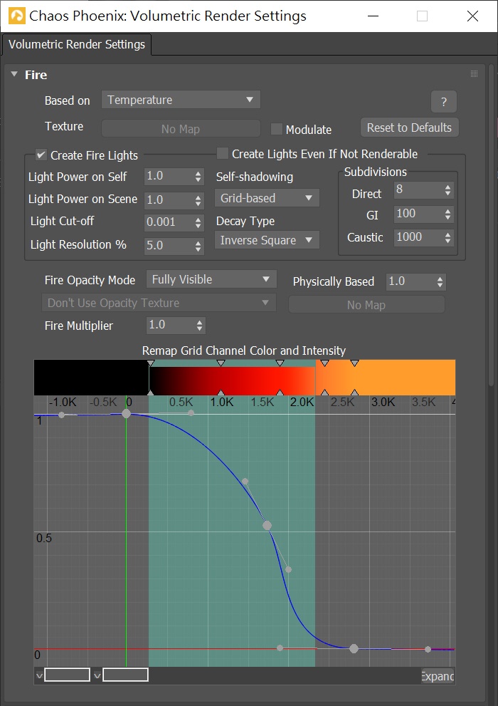
Go to the Fire/Smoke Simulator → Rendering rollout, click on Volumetric Options. Adjust the color gradient and the curve as shown in the image.
The color gradient is set to black-red-orange-yellow representing fire color at different temperatures, from coolest to hottest. Note that the green region highlighted in blueish-green shows the temperature data range for the current timeline frame. When you scrub the timeline, this area changes as the grid content changes. In this case we have fire temperatures ranging from 0 to around 2250 Kelvins. When you set the color ramp and curve, make sure they are within the range of the green area because this is the data that will actually be rendered for this frame.
Use an S-shaped curve. From left to the right, the curve begins with the highest value of Y, then goes down at the highest temperature. By doing so, Phoenix retains most of the details for the higher temperatures, avoiding color washout.
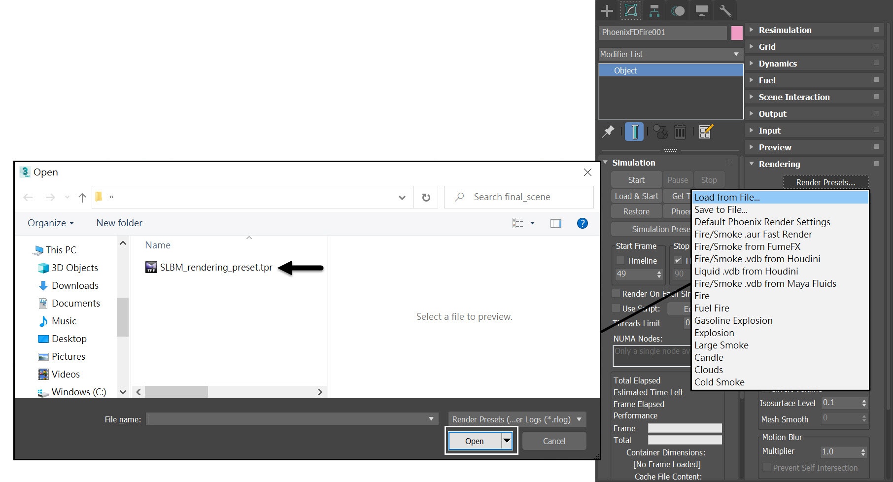
Alternatively you can simply load up a Rendering Preset from the SLBM_rendering_preset.tpr file that is provided in the sample scene.
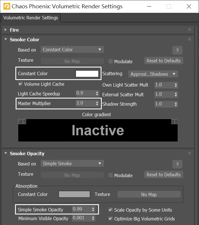
In the Smoke Color roll out, set the Constant Color to pure white (RGB: 255, 255, 255). Increase the Master Multiplier to 2.0.
Even though we set the smoke color to pure white, it might look gray when rendering. We adjust the Master Multiplier of the Smoke Color to a higher value ensuring enough whiteness.
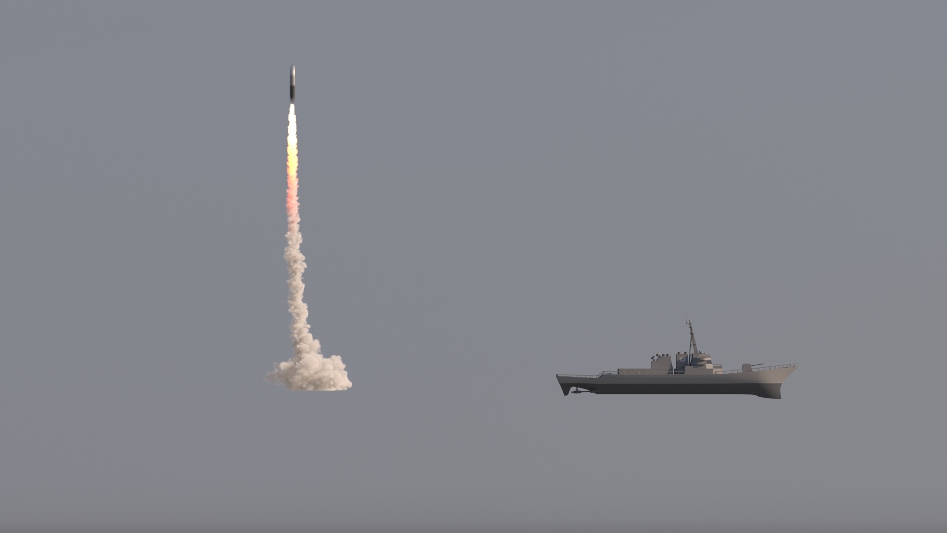
Here's a render of the current scene.
Smoke Absorption color
To further enhance the realism of the smoke trail, select the Phoenix Fire/Smoke Simulator, go to Rendering rollout → Volumetric Options. In the Smoke Opacity rollout, set the Absorption Constant Color to RGB (96, 96, 117).
In this tutorial, the Absorption Constant Color is set to sky blue, but you can choose other colors that match your environmental lighting.

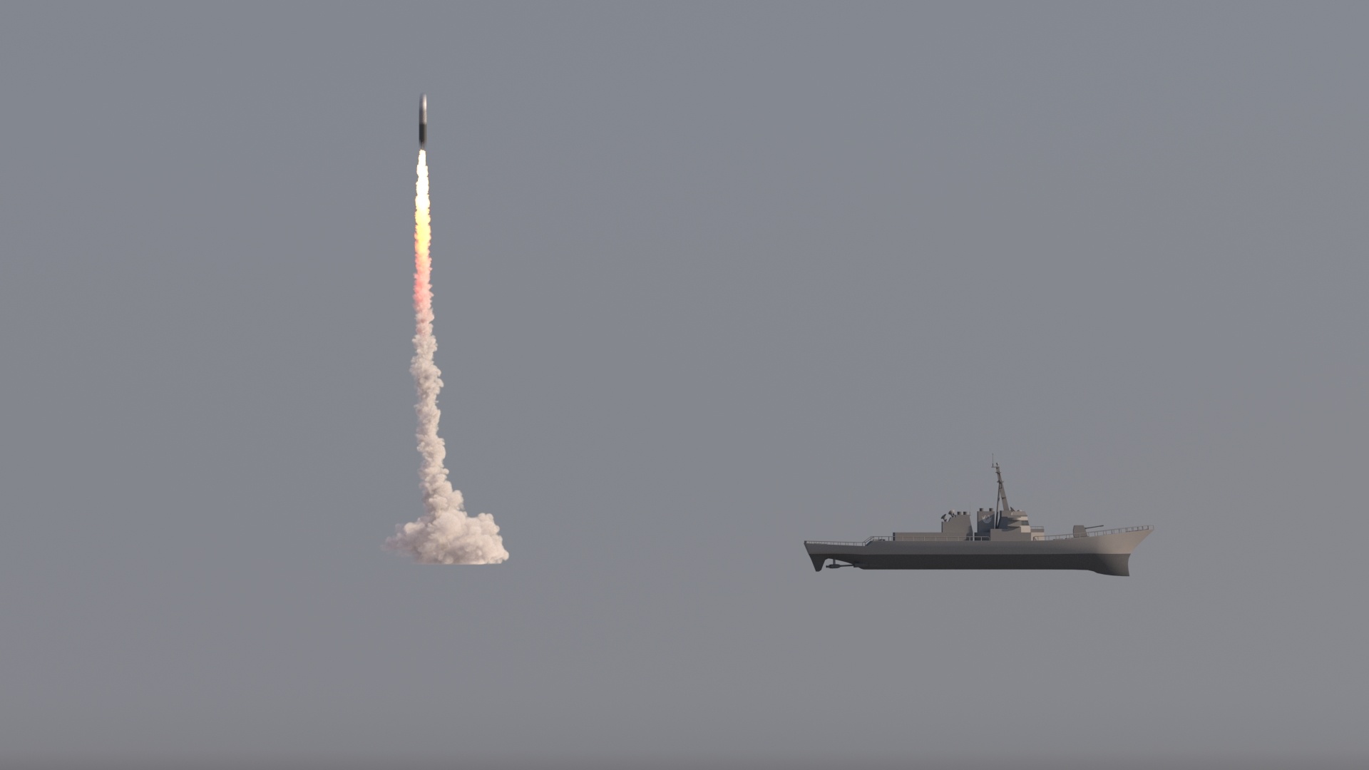
Now we have a white smoke trail with a subtle bluish tint. The ratio of the hot afterburn to the cold smoke trail looks convincing.
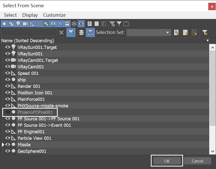
The Fire/Smoke Simulation is completed. Now let's move on to the liquid part of this tutorial. In the Scene Explorer, click on the Eye Icon on the left of PhoenixFDFire node entry, to hide the Phoenix FD Fire / Smoke Simulator.
Liquid Simulation
Go to Create Panel → Create → Geometry → PhoenixFD → PhoenixFDLiquid.
The exact position of the Simulator in the scene is XYZ: [ 0.0, 0.0, 0.0 ].
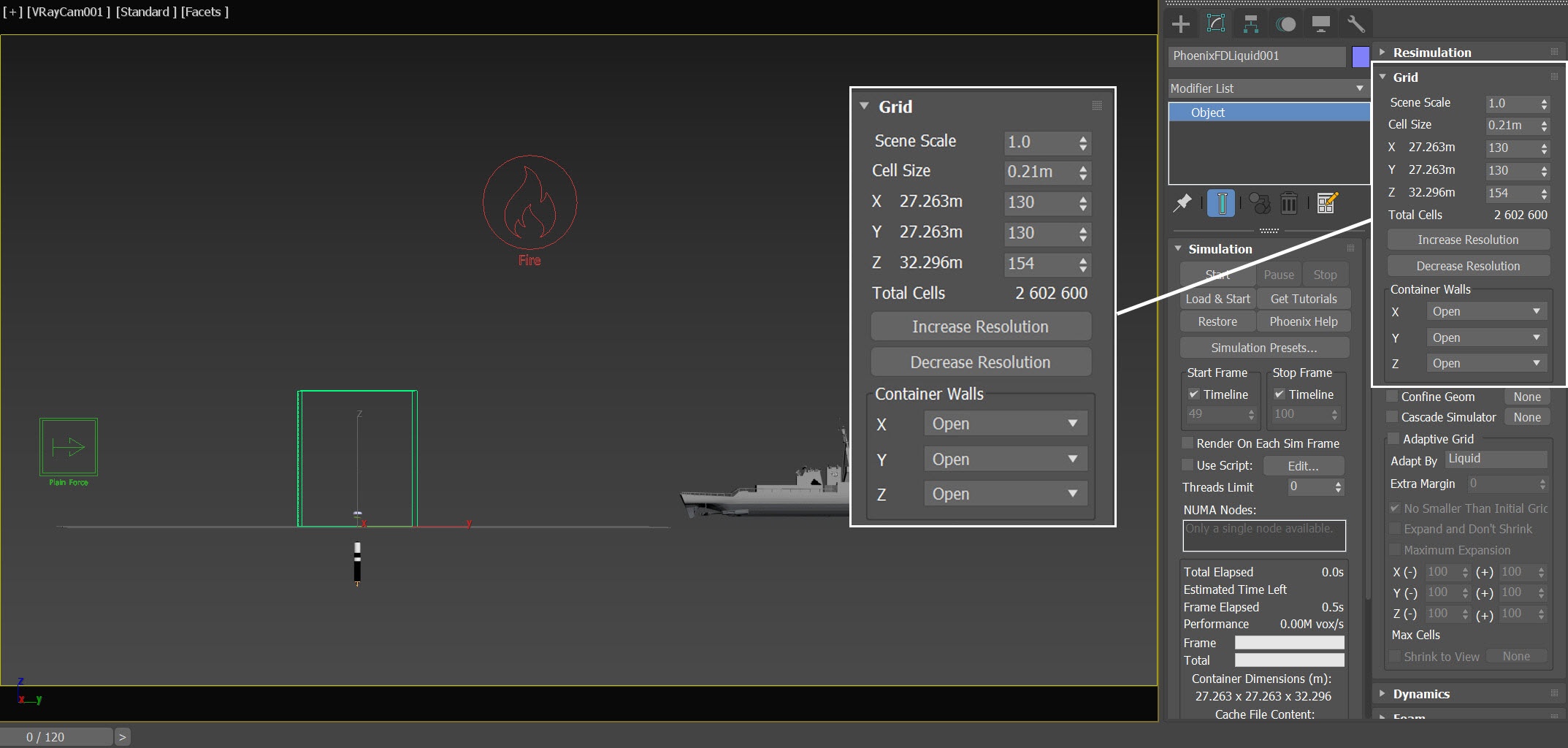
Open the Grid rollout and set the following values:
- Cell Size: 0.21 m
- Size XYZ: [ 130, 130, 154 ]
- Container Walls: Open to X, Y and Z
The Simulator size roughly covers the splashes of the missile launch. This optimizes the simulation and avoids cropping the particles at the simulator's boundaries.
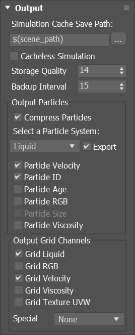
Select the PhoenixFDLiquid → Output rollout . Leave everything as default.
Select the PhoenixFDLiquid → Scene Interaction rollout. Press Add and choose PF Source in the Scene Explore.
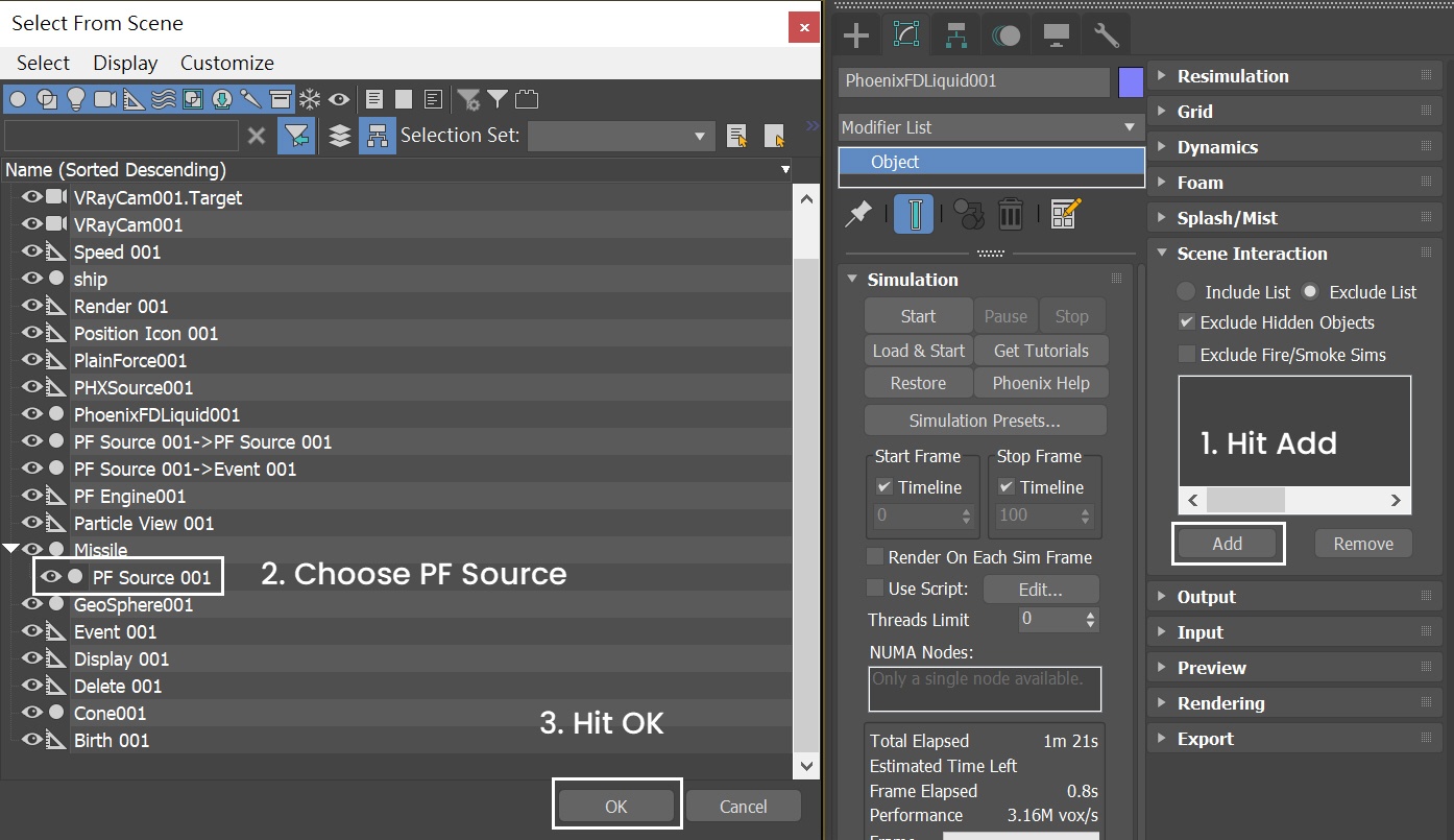
Prompt the Available Events. Choose both the "PF Source 001→PF Source 001" and "PF Source 001→Event 001". Press OK. Now all PFlow particles are exclude from the liquid simulation.
If PF Source is not added in the Scene Interaction exclude list, the particles will push the liquid during simulation and create undesired effects.
List of Liquid Sources and their Settings
Here are three Liquid Sources that will be used:
- The Missile is the first geometry used for a liquid source.
- Geosphere will be added as a liquid source to enhance the splashes.
- Cone geometry is added to generate a large number of splashes after the Missile smoke hits the ocean surface.
Liquid Sourcre | Emit From | Emit Mode | Outgoing Velocity | Emitting Particles | Motion Velocity |
|---|---|---|---|---|---|
LiquidSrc-Missile | Missile | Surface Force | Frame 19 – 2 4 -> 0 | - | 1 |
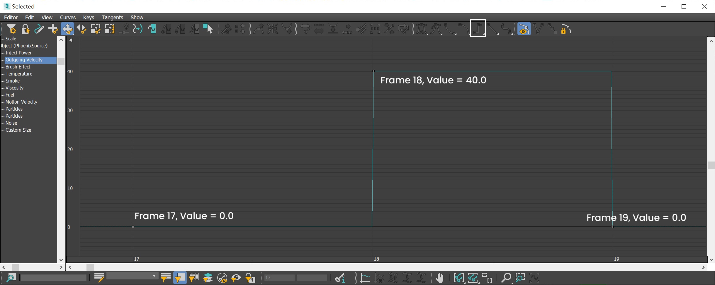
LiquidSrc-GeoSphere | GeoSphere | Surface Force | Frame 18 – 19 40 -> 0 | - | - |
LiquidSrc-Cone | Cone | Surface Force | Frame 59 – 61 70 -> 0 | Splashes | - |
Adding Missile Liquid Source
Create a Phoenix Liquid Source in the scene: Create Panel → Create → Helpers → PhoenixFD → PHXSource. Rename it to LiquidSrc-Missile.
Press the Add button to choose which geometry to emit and add Missile entry to the Scene Explorer.
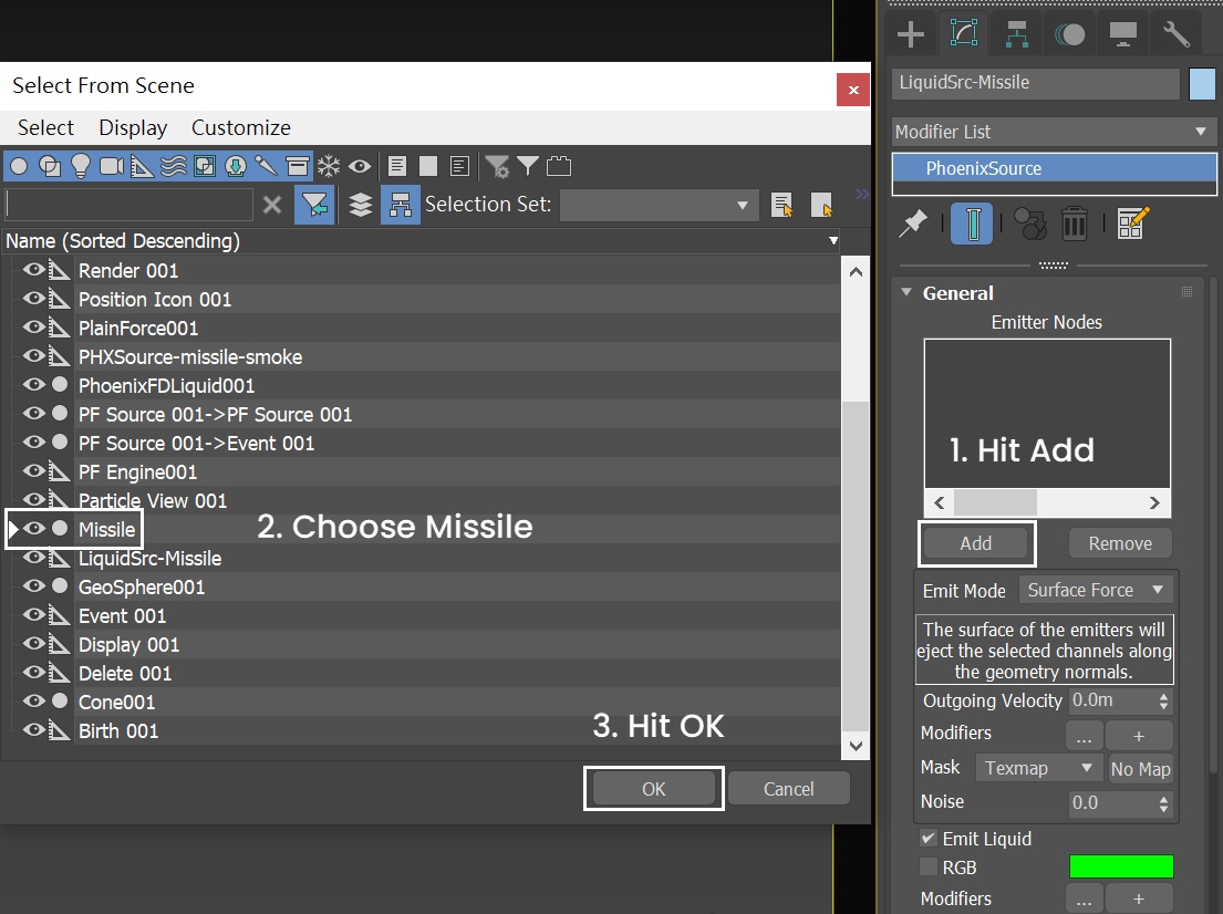
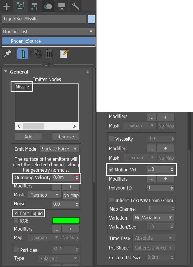
For the LiquidSrc-Missile:
- Set the Emit Mode to Surface Force and animate the Outgoing Velocity value.
- Enable Emit Liquid.
- Set Motion Vel. to 1.0
Go to Graph Editors/Track View → Curve Editor and set keys to the curve of the Liquid-Missile's Outgoing Velocity. We set keyframes to the Outgoing Velocity, so it can change over time. The frames and values are shown in the screenshots.
The Curve corresponds to the Missile launch from underwater and gradually loses its speed.
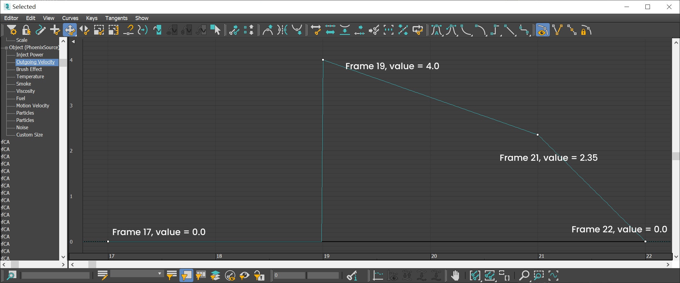
Here is the table for the keyframes of Liquid-Missile's Outgoing Velocity.
Frame | Value | Tangent type |
|---|---|---|
17 | 0.0 | Stepped |
19 | 4.0 | Linear |
21 | 2.35 | Linear |
22 | 0.0 | Linear |
Set Initial Fill Up
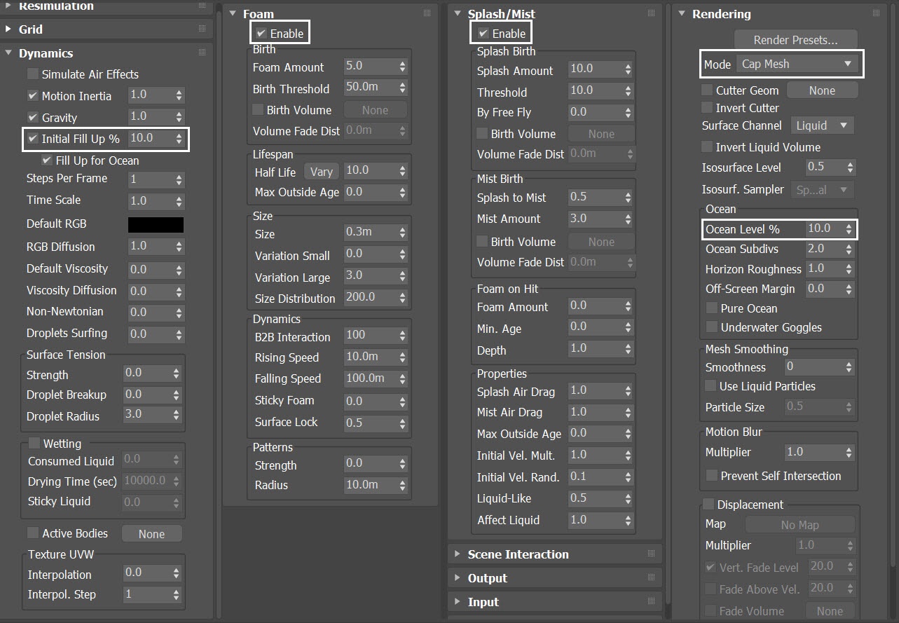
Select the PhoenixFDLiquid in the scene→ Dynamics rollout. Set the Initial Fill Up % to 10.0. Enable both Foam and Splash/Mist option. Leave everything at default.
In the Rendering rollout, set the Mode to Cap Mesh. Set the Ocean Level % to 10.0. It's the same value as the Initial Fill Up.
The desired effect is the Splash / Foam / Mist particles to generate when the missile launches. Waves and liquid particles are not so important. Therefore, we minimize the Initial Fill Up to 10%, to save us some simulation time.
During the development stage, set the rendering mode to Cap Mesh, since it is lighter in the viewport.
Setting Particle Shaders
Enable the Foam option. When asked if you'd like a Phoenix Particle Shader generated for the Foam particles, click on Yes, . This will automatically set up the link between the Foam particles group, the Shader, and the Liquid Simulator. Same goes when you enable the Splash/Mist option for the Splash.
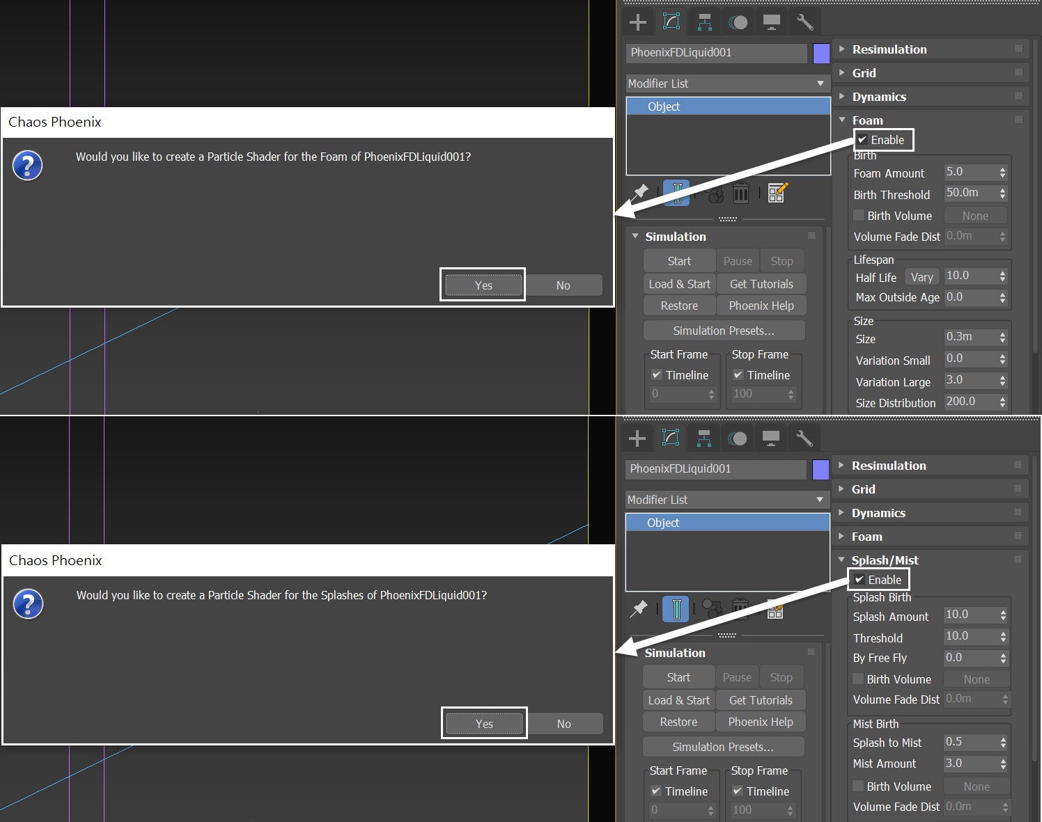
Now there are two Particle Shaders in the scene. Rename them to ParticleShader-Foam and ParticleShader-Splash respectively.
Set the Mode of the ParticleShader-Foam to Points. Leave the other settings as default for now.
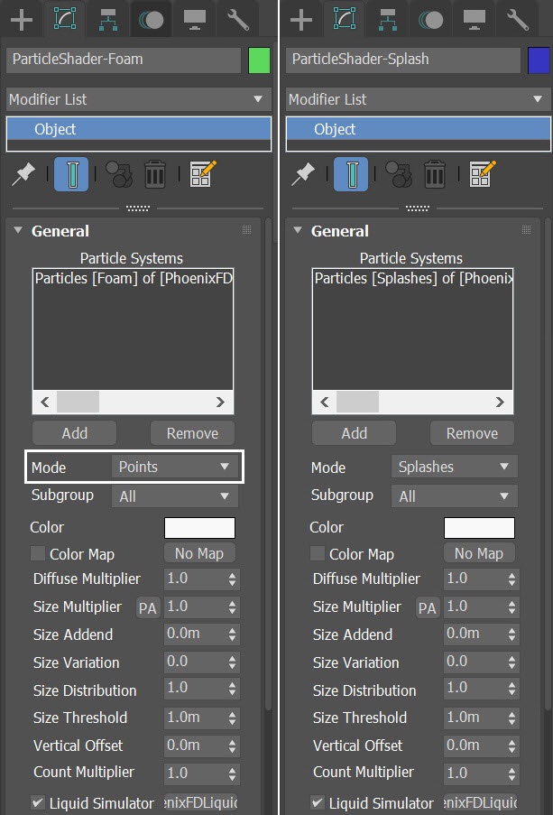
As for the Mist particle, you have to create a new Particle Shader for it manually.
Go to: Create Panel → PhoenixFD, Click on the PHXFoam button to create a new Particle Shader in the scene. Rename it to ParticleShader-Mist.

With the PhoenixFDLiquid Simulator selected, simulate for one frame. This step allows Phoenix to generate a Foam / Splash / Mist particles list in the scene.

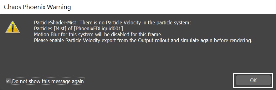
With the ParticleShader-Mist selected, go to the Modifier Panel. Press the Add button to choose the PhoenixFDLiquid entry in the Scene Explorer, then press OK.
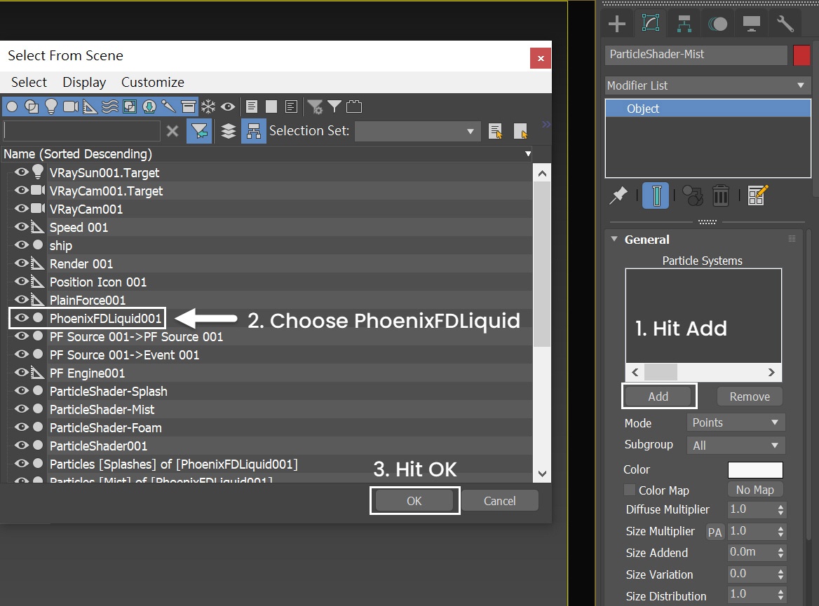
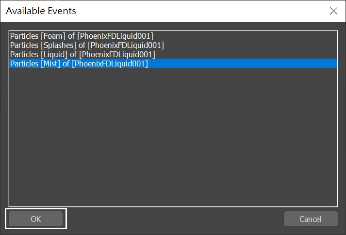
Prompt the Available Events window, choose the Particle[Mist]of[PhoenixFDLiquid001]. Press OK.
If Phoenix has not ran the Liquid Simulation before, you will not see any particles in the list of Available Events.
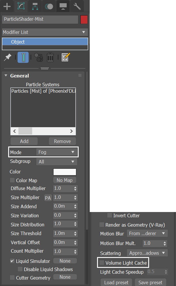
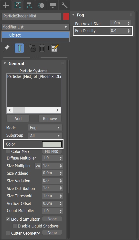
Set the ParticleShader-Mist's mode to Fog. Disable the Volume Light Cache option.
Now three Particle Shaders for the Foam / Splash / Mist particles are all set.
The Volume Light Cache for the ParticleShader-Mist needs to be disabled, otherwise you will see obvious GI flickering in the final rendering where the mist particles are distributed. This is because in this special case we have a Fire / Smoke Simulator in the scene.
You can see splashes coming out of the water when the missile is launched. But there are not enough splashes and the distribution of the particle formation is not optimal.
The Plain Force we have created in the previous step will also blow away the particles simulated from the Liquid Simulator.
(Please replace this image with SLBM_Step11.mp4)
Change Preview Color
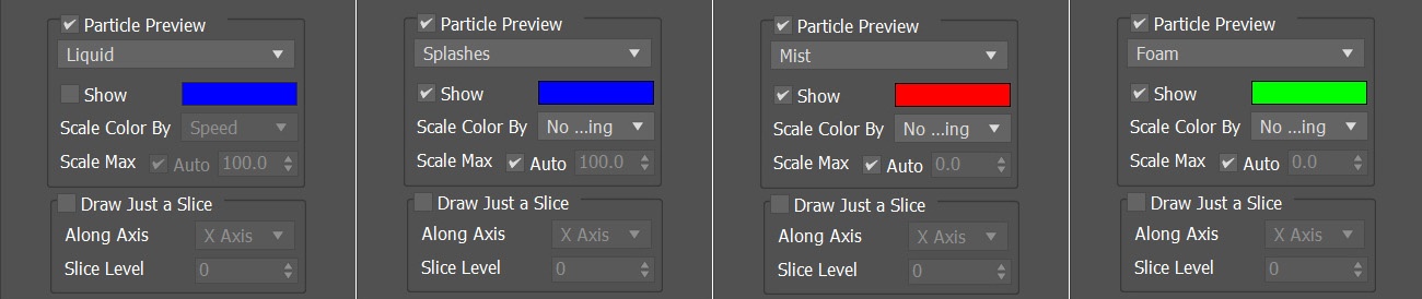
To see which particles are which more clearly, let's change the color swatches for the different particle types. Select the PhoenixFDLiquid in the scene→ Preview rollout. Set the Splash, Mist, and Foam to Blue (RGB: 0, 0, 255), Red (RGB: 255, 0, 0), and Green(RGB: 0, 255, 0) color respectively.
Disable the Liquid Preview by unchecking its Show option. So we can see the distribution of the Splash / Mist / Foam particles simply by their color.
Set Scale Color By to No Scaling for all particle types.
The exact RGB color for the particle preview is not critical. You can choose other colors as long as they are distinguishable.
Here is a preview of the simulation.
The Mist particles outnumber the Splash ones and they are overlapping. This makes the Blue Splash Particles barely visible in the preview.
(Please replace this image with SLBM_Step12-Particle-Color.mp4)
Adjusting the Foam amount
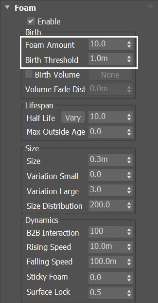
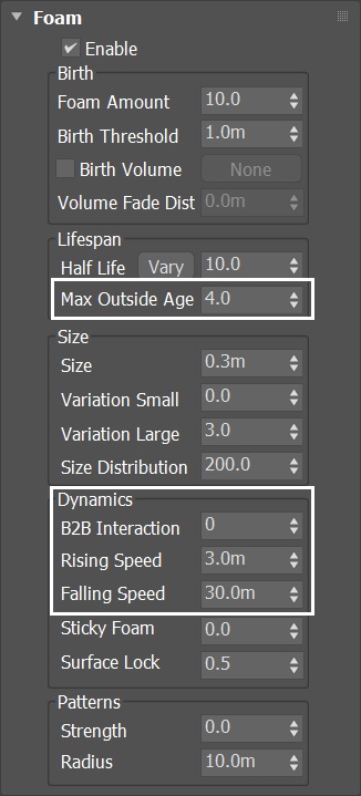
Select the PhoenixFDLiquid in the scene→ Dynamics rollout. In the Foam rollout, increase the Foam Amount to 10.0. Lower the Birth Threshold to 1.0m.
Run the simulation with the new settings.
You can see more Foam particles are generated after the Missile launch. However, the Foam rises too fast and is cropped by the Simulator.
(Please replace this image with SLBM_Step13-Foam.mp4)
Increase Foam Max Outside Age
Select the PhoenixFDLiquid in the scene →Foam rollout. Set the Max Outsize Age to 4.0. B2B Interaction to 0. Decrease the Rising Speed to 3.0m. Decrease the Falling Speed to 30.0m.
Run the simulation with the new dynamics settings.
To prevent any cropping at the Simulator's boundaries, instead of increasing the height (z) of the Simulator, we simply increase the Max Outsize Age of the Foam. The unit for the age is in Seconds. Since the scene's FPS is set to 30. Therefore the Foam particles will last for 4 X 30 = 120 frames. Enough time for the Foam particles to display throughout the whole animation.
The B2B Interaction controls the internal interaction between Bubbles (bubble-to-bubble interaction). This option is used when the Foam particles should have a volume. It forces a proper distance between the Bubbles and keeps them stuck together. This parameter controls the number of interactions per second. Higher values result in better preservation of the Foam's volume. In this case, the interactions are not so critical, therefore we set it to zero.
Now we have Foam particles shooting up and they continue flying even outside of the Liquid Simulator's boundaries.
(Please replace this image with SLBM_Step14-Foam-Dynamics.mp4)
Adjust Splash / Mist
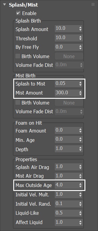
Select the PhoenixFDLiquid in the scene →Splash/Mist rollout. Reduce the Splash to Mist to 0.05. Increase Mist Amount to 300.0. Set the Max Outsize Age to 4.0.
Run the simulation again with the new dynamics settings.
Not much Mist is needed. Reduce the Splash to Mist to 0.05.
Here is a preview of the simulation.
(Please replace this image with SLBM_Step15-Mist.mp4)
Adding Geosphere liquid Source
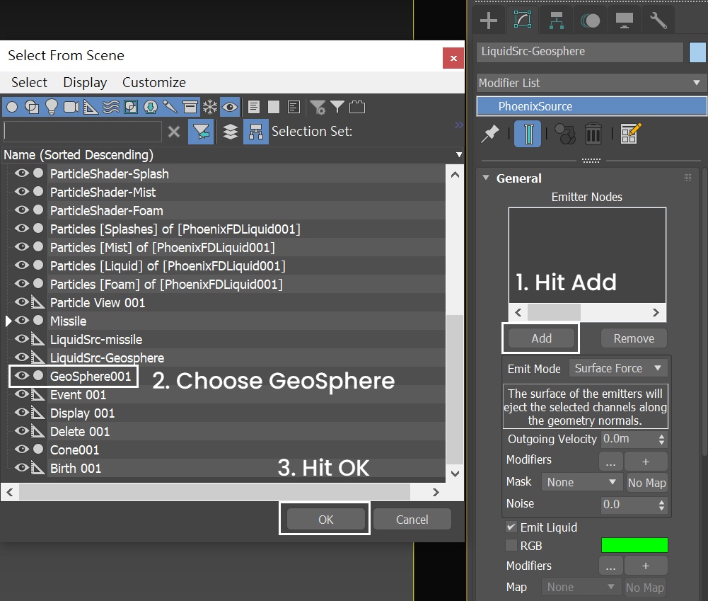
The shape of the Splash from the Missile and the amount of Splash is not enough. Create another Liquid Source in the scene. Create a Phoenix Liquid Source in the scene: Create Panel → Create → Helpers → PhoenixFD → PHXSource. Rename it to LiquidSrc-Geosphere.
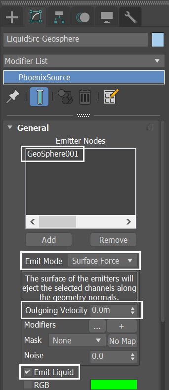
Press Add to choose which geometry to emit. Click on the GeoSphere entry in the Scene Explorer.
For the LiquidSrc-Geosphere:
- Set the Emit Mode to Surface Force and animate the Outgoing Velocity value.
- Enable Emit Liquid.
Go to Graph Editors/Track View → Curve Editor and set keys to the curve of LiquidSrc-Geosphere's Outgoing Velocity.
Set the keyframes to Outgoing Velocity, so it can change gradually. The frames and values are shown in the screenshots.
Set keyframes to Tangents to Stepped.
Run the simulation again.
On Frame 18 the missile emerges from the ocean. If you change the animation of the missile, you might need to adjust the animation curve for the Outgoing Velocity of LiquidSrc-Geosphere accordingly.
As you can see, now the Splashes coming out of the sea are stronger.
(Please replace this image with SLBM_Step16-Geosphere.mp4)
Adding Cone Liquid Source
Create a Phoenix Liquid Source in the scene: Create Panel → Create → Helpers → PhoenixFD → PHXSource. Rename it to LiquidSrc-Cone.
Press the Add button to choose which geometry to emit. Click on the Cone entry in the Scene Explorer.
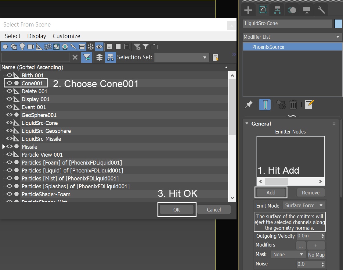
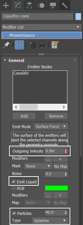
For the LiquidSrc-Cone:
- Set the Emit Mode to Surface Force and animate the Outgoing Velocity value.
- Enable Emit Liquid.
- Enable Particles. Set the Type to Splashes with value of 40.0
Go to Graph Editors/Track View → Curve Editor and set the keys to the curve of LiquidSrc-Cone's Outgoing Velocity.
Set the keyframes to Outgoing Velocity, so it can change over time. The frames and values are shown in the screenshots.
All keyframes are set to Tangents to Stepped.
Run the simulation again.
Frame 59 is when the Missile Smoke Burst hits the ocean surface. Increase the Outgoing Velocity at Frame 59.
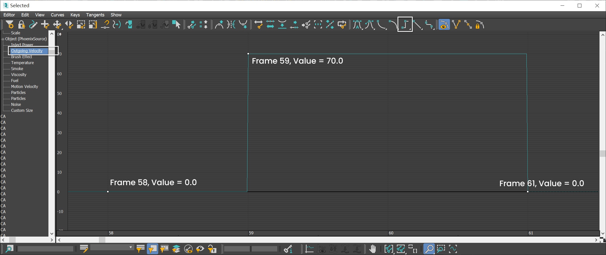
You can see a large number of Splashes coming out of the ocean when the missile smoke hits the ocean surface.
The slope of the Cone gives the desired shape of the Splashes for this tutorial. You can customize your Splashes with a different geometry.
In this example, the interaction between Smoke / Fire Simulation and the Liquid simulation is mocked.
(Please replace this image with SLBM_Step17-Cone.mp4)
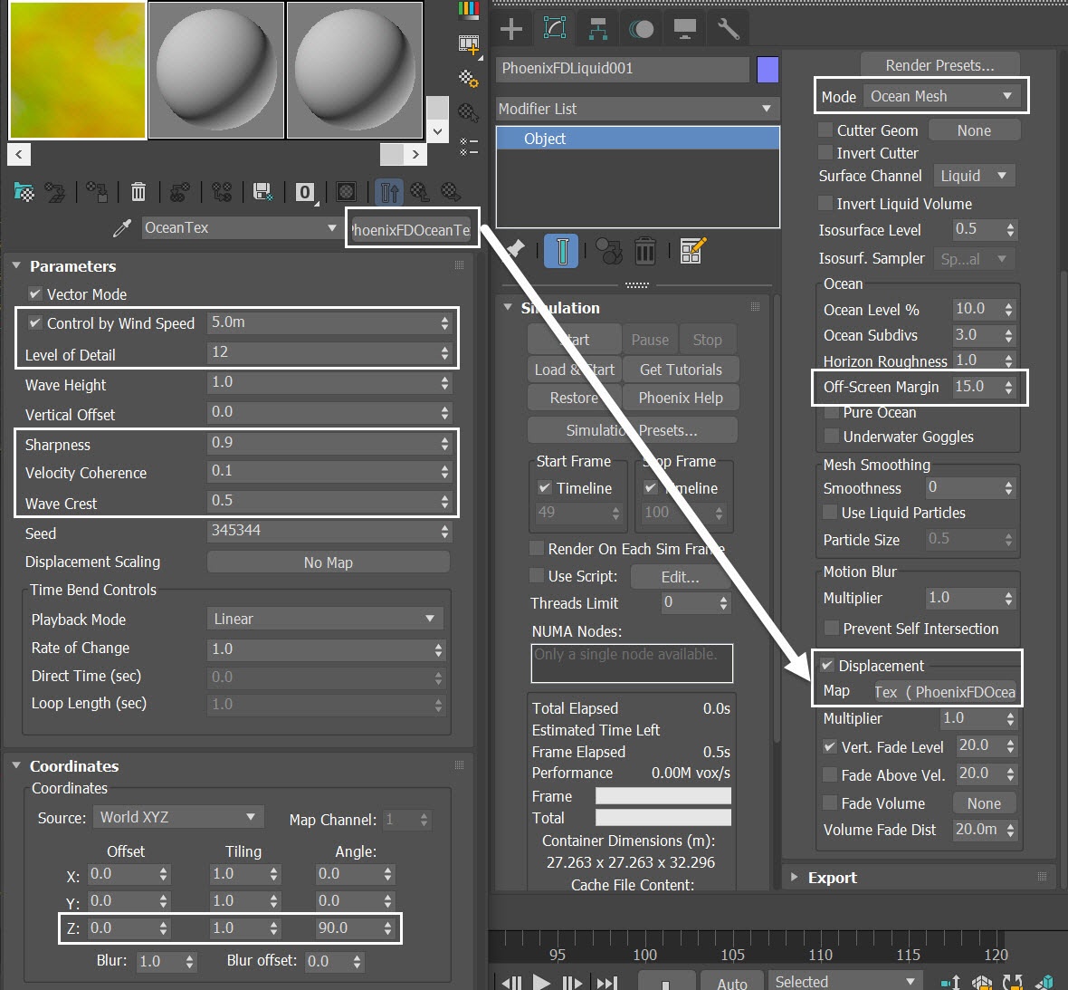
Set up Ocean Texture for displacement
With the PhoenixFDLiquid selected, go to the Rendering rollout and switch the Mode to Ocean Mesh. Set the Off-Screen Margin to 15.0.
If you don't give some value to the Off-Screen Margin for the ocean, you will get an unwanted pop-up of the ocean surface when the displacement is applied. If that's the case, the problem will show between Frame 99 to Frame 100 at the edge of the ocean.
To add details to the ocean surface, enable the Displacement option. plugin a PhoenixFDOceanTex in the Map lot.
Click and drag it to the Material Editor (as the Copy option creates a copy of this Map - you want to use the same texture for both sources, instead of being forced to deal with 2 separate PhoenixFDOceanTex). Rename the texture to OceanTex.
Here are the values for the OceanTex parameters:
- Control by Wind Speed to 5.0m
- Level of Detail to 12
- Sharpness to 0.9
- Velocity Coherence to 0.1
- Wave Crest to 0.5
Set Coordinates Z Angle to 90.0, so that the direction of the ocean waves aligns with the direction of the PlainForce in the scene.
If you change the orientation of the PlainForce, adjust the Coordinates of the Ocean Texture Map accordingly.
Note the value of Wind Speed set for the PhoenixFDOceanTex is the same as the PlainForce set for the Missile smoke trail in the previous step. These coordinated settings make the shot visually more convincing.
Velocity Coherence controls the degree of variation in Wave Direction. When this value is set to 1, all waves will move in the same direction, as they do in coastal areas. When set to 0, all waves will move in random directions, as they might in the open seas.
345344 is the default value for the PhoenixFDOceanTex's speed. Leave it at default value.
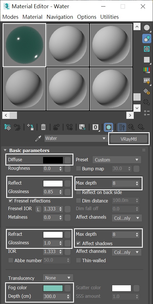
Water Material
Create a V-Ray Material and assign it to the PhoenixFDLiquid Simulator.
Set the Diffuse color to black.
Reflect and Refract colors should be set to white - this will produce a completely transparent material if the Index of Refraction was set to 1 (which is the IOR of clear air).
Set Max depth to 8 for both Reflection and Refraction.
Set the IOR to 1.333 - this is the physically accurate Index of Refraction of water.
Reduce the HGlossines (Highlight Glossiness) to 0.85. This will slightly blur the specular highlights produced by the sources of illumination in your scene.
If you were to hit render now, you'd notice that the water is completely transparent and does not look like an ocean.
Instead, set the Fog color to RGB : [53, 146, 125 ] and set the Depth to 300.0. This should produce the type of shading you'd expect in a large body of water containing all sorts of particulates that interfere with the light rays.
In the Scene Explorer, click on the Eye Icon on the left of PhoenixFDFire node entry, to unhide the Phoenix FD Fire / Smoke Simulator. Now we are ready to render both the Liquid and the Fire / Smoke effects in the scene.
The Mist looks too thin in the shot.
Adjusting the Particle Shaders
With the ParticleShader-Mist selected, set the Color swatch to Gray (RGB: 155, 159, 148). Increase the Fog Density to 0.4.
Now the Mist appears thicker. However, the Foam appears too grainy. Both Foam and Splash look overexposed.
With the ParticleShader-Foam selected, set the Color swatch to a Bluish-White color (RGB: 180, 198, 198). Decrease the Point Radius to 0.5.
The Point Radius controls particle size in pixels. Therefore, the apparent radius in a final rendered image is affected by the image output resolution. You can find an example here.
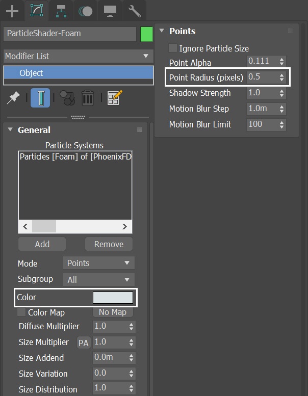
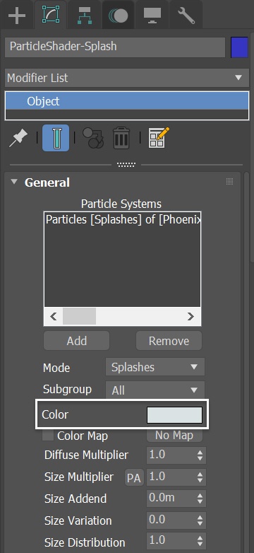
With the ParticleShader-Splash selected, set the Color swatch to a Bluish-White color (RGB: 180, 198, 198).
The Foam looks thinner now. But you can still see black artifacts on the ocean surface, especially the far side of the ocean.
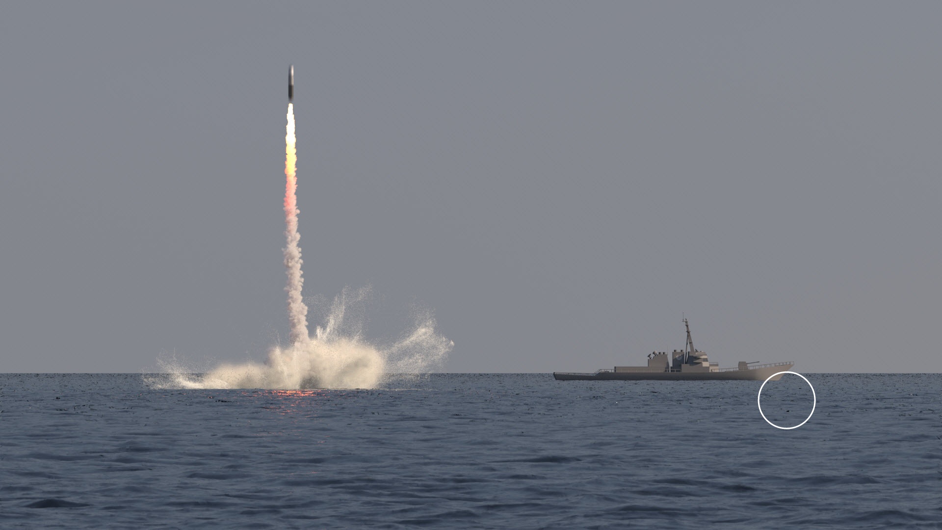
Alleviate the Ocean mesh artifact
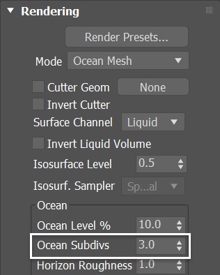
With the PhoenixFDLiquid selected, go to the Rendering rollout and increase the Ocean Subdivs to 3.0.
When generating the far areas of the surface, the Ocean Subdivs determines how many vertices will be generated for each pixel of the image. Like with V-Ray subdivisions, the square of the parameter value is used. For example, if you increase the number of subdivisions twice, the number of vertices will grow four times. Do not to set the value too high.
As you can see, increasing the Ocean Subdivs alleviate the black artifacts on the ocean surface.

perturbations
V-Ray Frame Buffer
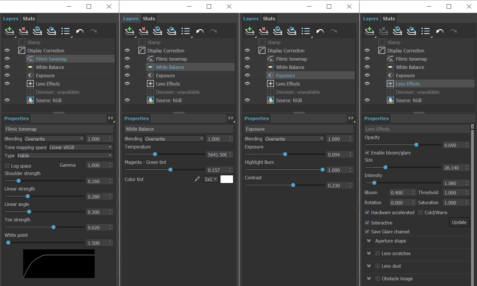
Open the V-Ray Frame Buffer and use the Create Layer icon to add layers for Lens Effects, Exposure, White Balance and Filmic Tonemap.

The final image is rendered using the V-Ray Frame Buffer with the color corrections and post effects set to:
Filmic Tonemap:
- Type - Hable
- Shoulder strength: 0.160;
- Linear strength: 0.280;
- Linear angle: 0.300;
- Toe strength: 0.620;
- White point: 1.500.
White Balance:
- Temperature: 5641.5.
Exposure:
- Exposure: 0.094;
- Highlight Burn: 1.0;
- Contrast: 0.230.
Lens Effects:
- Opacity: 0.690;
- Size: 26.140;
- Intensity:1.080;
- Bloom: 0.400;
The Filmic Tonemap allows to simulate film's response to light with VFB.
Feel free to use other values for those post effects depending on your preferences.
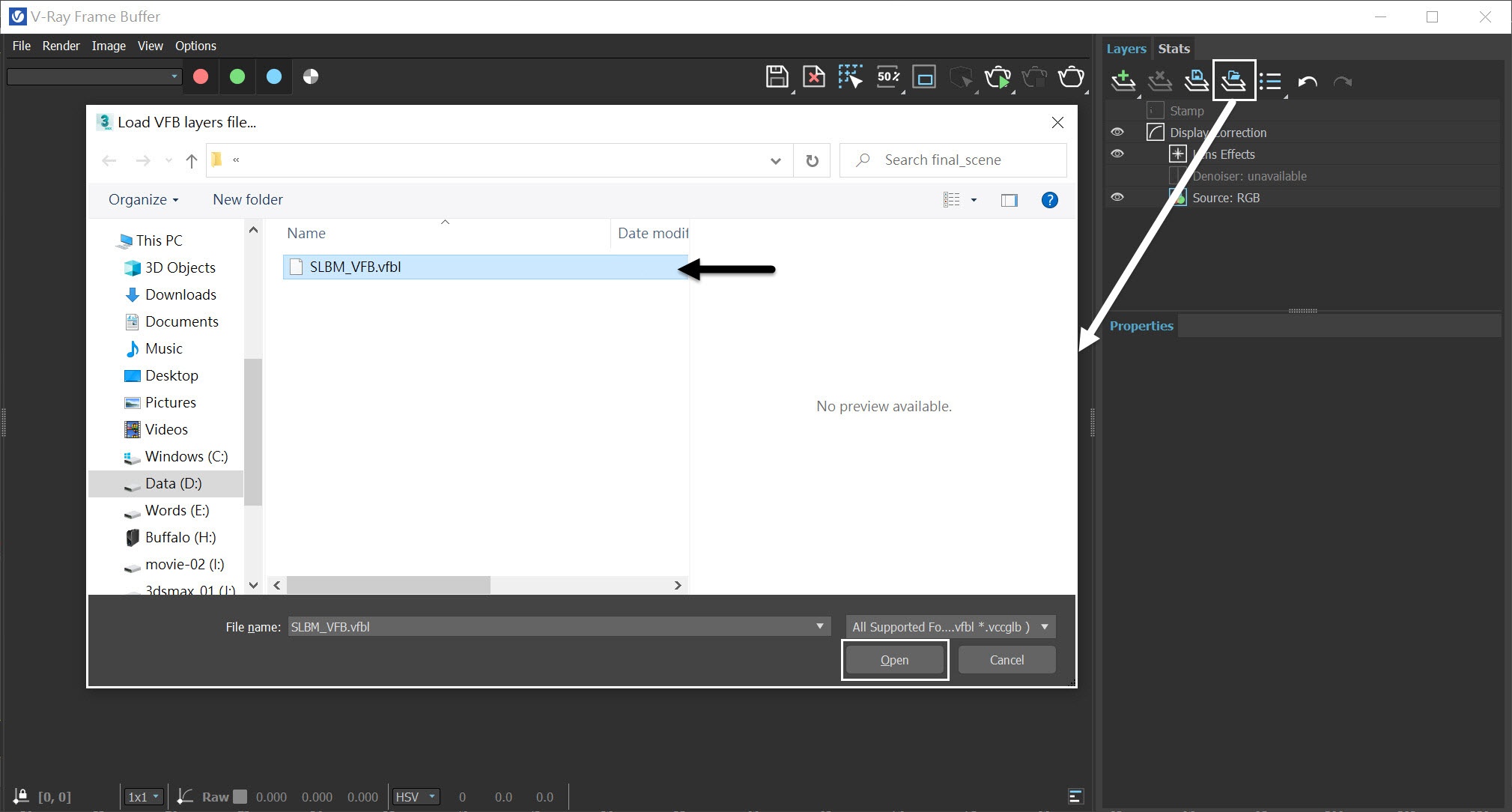
Alternatively, you can simply load up a Rendering Preset from the SLBM_VFB.vfbl file that is provided in the sample scene.
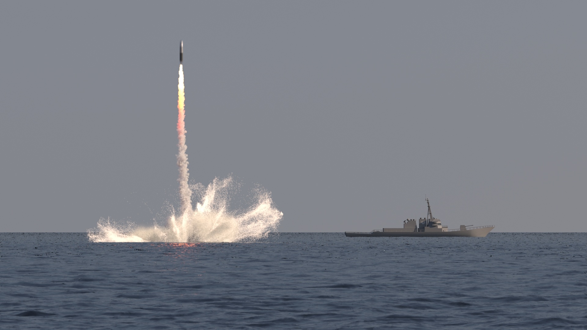
And here is the final rendered result.
(Please replace this image with SLBM_final.mp4)