This page contains information on getting started with Phoenix FD for 3ds Max.
Overview
To create fire and liquid effects, Phoenix FD creates objects and helpers in the scene. Phoenix FD provides several Quick Simulation buttons that create these scene elements for you, with settings for common scenarios. You can also create these objects and helpers manually.
If you are just getting started with Phoenix FD, it is recommended that you use the Quick Simulation buttons and become familiar with the scene elements they create. As your experience with Phoenix FD increases, you will be in a better position to create these scene elements manually and set parameters appropriately.
Preparing a Simulation
To create a simulation, you'll need an object or objects to emit the fire or liquid, called emitters. Emitters can be ordinary 3ds Max objects such as a Box, Cylinder, Editable Poly, or Editable Mesh. It is not necessary to collapse the objects to an Editable Mesh or Editable Poly; object(s) with modifiers on the Modifier Stack will still emit correctly.
For a liquid simulation of pouring liquid, you can also include a vessel to catch or deflect the liquid. For example, for a simulation of beer pouring into a glass, you'll need an object to represent the beer glass that will deflect and contain the falling liquid.
The examples below show some log objects ready for burning, and a simple setup for water coming out of a spigot and into a trough. For the fire setup, the logs themselves will be the emitters. For the water setup, a small planar object inside the spigot (not visible in the image) will emit the water, which will fall into the trough. The trough is slightly angled away from the spigot end so the water will flow away from it.
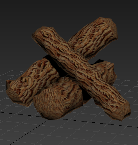
Log objects
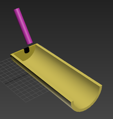
Simple setup for spigot and trough
When possible, build emitters and vessels to real-world scale. Since Phoenix FD uses real-world calculations to create its effects, working with real-world units will make your work much easier.
By default, Phoenix FD assumes the World Z axis to be the "up" direction for the simulation. As in real life, fire will rise "up" due to its heat while liquid will flow "down" due to gravity unless otherwise specified. Building your emitters and vessels with regard to the default "up" direction will make it much easier to create simulations with Phoenix FD.
Fire Simulation
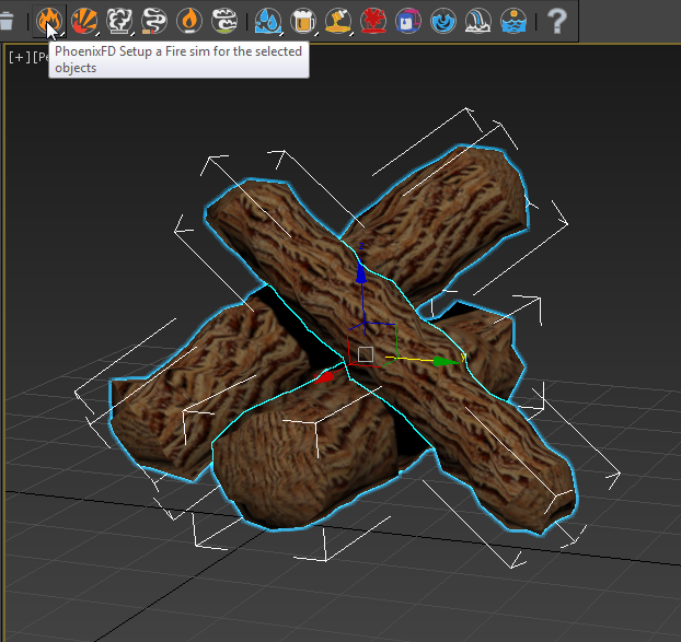
To create a fire simulation, select the object(s) you wish to burn and click the Fire sim Quick Simulation button on the Phoenix FD toolbar.
The Fire sim Quick Simulation button creates three objects in the scene and sets up their parameters for a fire simulation:
- PhoenixFDFire object - A box-shaped object that represents the grid within which the simulation takes place. The grid shape encompasses the emitter objects and also leaves space above the objects for the fire to flow. This non-rendering object is required for the simulation.
- PHXSource helper - A helper (labeled Fire in the viewport) that associates the emitter(s) with the simulation. This helper is required for the simulation.
- PHXTurbulence helper - A helper (labeled Turbulence in the viewport) that creates turbulence in the simulation. This helper is optional, and is added to the Quick Simulation setup to improve the results of the simulation.
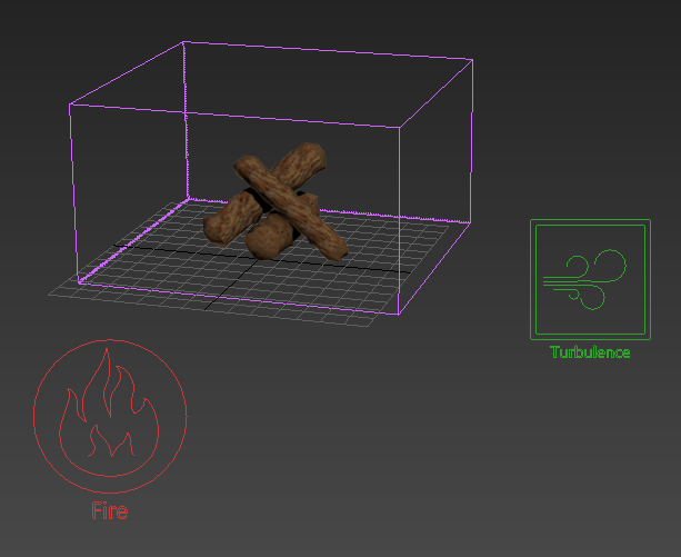
Scene elements created by Fire sim Quick Simulation button
With all the scene elements in place, you can now run the simulation. See Running the Simulation below for the next steps.
Liquid Simulation
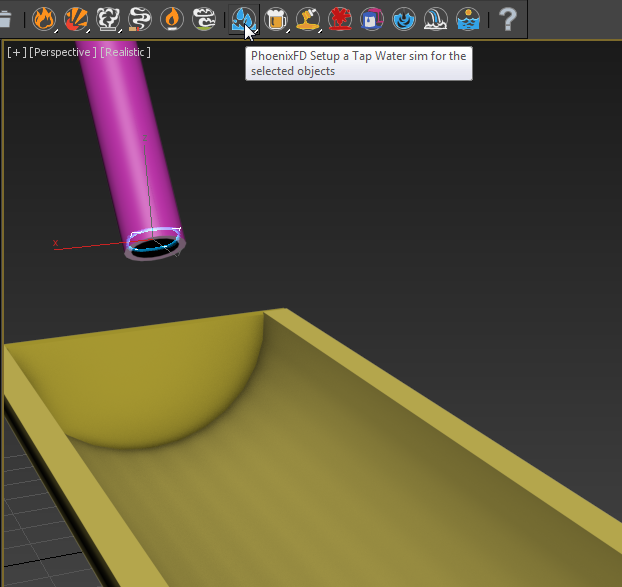
To create a liquid simulation, select the emitter object(s) and click the Tap Water sim Quick Simulation button on the Phoenix FD toolbar. Here, the small planar object inside the spigot is selected as the emitter.
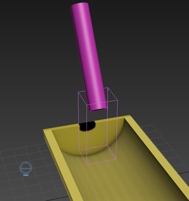
The Liquid sim Quick Simulation button creates two objects in the scene and sets up their parameters for a liquid simulation:
- PhoenixFDLiquid object - A box-shaped object that represents the grid within which the simulation takes place. The grid shape encompasses the emitter objects and also leaves space below the objects for the liquid to flow. This non-rendering object is required for the simulation.
- PHXSource helper - A helper (labeled Liquid in the viewport) that associates the emitter(s) with the simulation. This helper is required for the simulation.
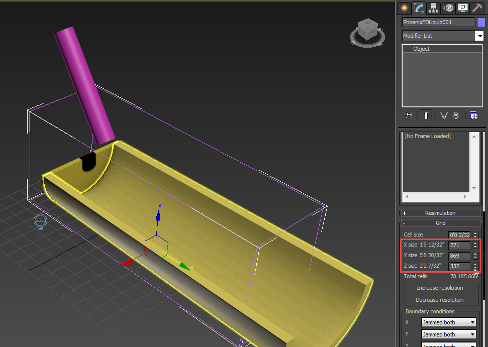
In this case, the grid that was automatically created is not large enough to encompass a simulation of water flowing down the trough. To increase the grid size, select the grid and change the X/Y/Z size parameters in the Grid rollout.
For objects that will contain or deflect the liquid, there is no need to select them as deflectors or collision objects. Phoenix FD will automatically detect them when the simulation is run, and will cause the liquid to react appropriately when it hits them.
Note: A liquid simulation uses geometry face normals to deflect and contain liquid, so any geometry that the liquid will hit needs to have its normals oriented to point away from the deflecting surface. With an object created with certain 3ds Max tools such as the Lathe modifier, it is not uncommon to find that the default normals point inside the vessel rather than outward from it. With such an object, the flow of the liquid won't be contained; the liquid will flow right through it. To check the normals, you can use the Edit Normals modifier or the XView Face Orientation option.
Running the Simulation
Once all the necessary scene elements are in place, you can run the simulation to see the fire or liquid effects in action.
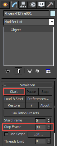
- Select the PhoenixFDFire object (the box around the emitters).
- On the Modify panel, locate the Stop Frame parameter in the Simulation rollout. Increase this value from 0 to a larger frame number such as 30.
- In the Simulation rollout, click the Start button. The simulation will begin to run.
While running the simulation, you will see the fire or liquid flowing in the active viewport. In addition, the grid might expand beyond its original size to allow the effect to flow into a larger area. You can also select other objects and continue working on the scene while the simulation runs.
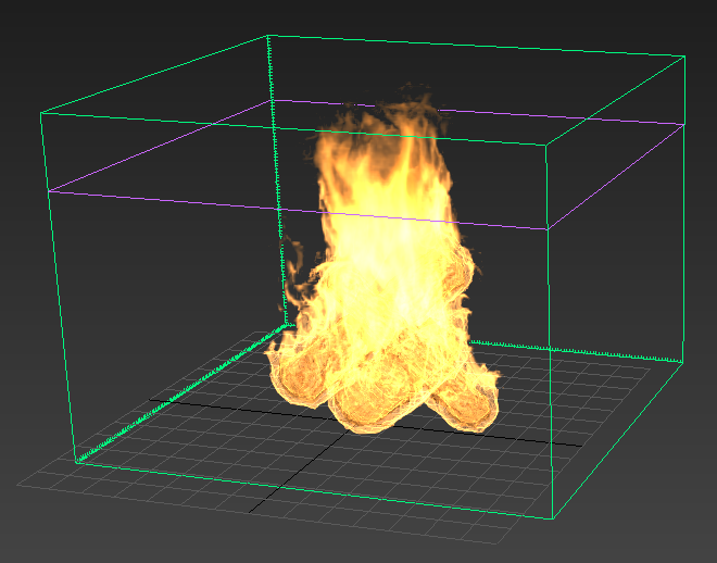
Log objects burning in viewport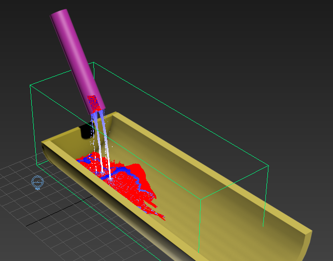
Liquid flowing in viewport
In a liquid simulation, you will see the liquid particles react to gravity and also get deflected or contained by any scene geometry they encounter, such as the trough. This collision detection occurs by default, even though you have not specifically designated the trough geometry as a deflector or collision object.
- If you wish to stop the simulation before it reaches the Stop Frame, select the grid and click the Stop button in the Simulation rollout.
- When the simulation is complete, render the scene as usual. The simulated effects will appear in the rendering.
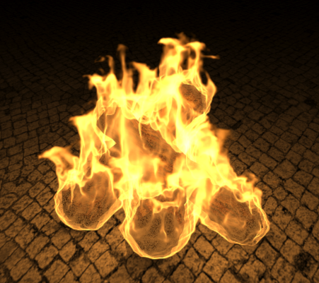 Fire sim result rendering
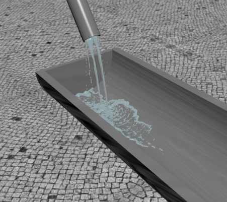
Liquid sim result rendering