
Bump
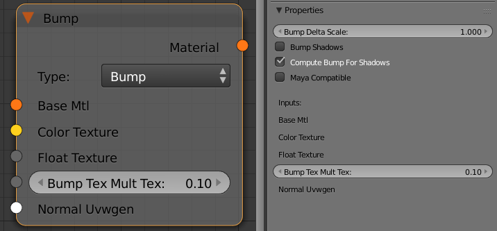 The Bump node allows you to add bump map or normal map effects when using any material.
Bump Delta Scale - scale for sampling the bitmap when using bump mapping. The exact value is calculated automatically by V-Ray, but can be scaled here.
Maya Compatible - when enabled V-Ray will render the bump mapping in such a way that it matches the result that can be achieved in Maya.
Bump Shadows - when this option is checked V-Ray will consider the bump maps when rendering shadows produced by objects with the bump material applied to them.
Type - allows the user to specify whether a bump map or a normal map effect will be added to the base material.
- Bump - normal bump map
- Normal (Tangent) - normal map in tangent space
- Normal (Object) - normal map in object space
- Normal (Camera) - normal map in camera space
- Normal (World) - normal map in world space
- From Bump -
- Explicit Normal -
Base Mtl - allows you to select the base material to which the bump/normal effect will be added.
Color Texture - you can use this slot to connect any 8bit texture
Float Texture - you can use this slot to connect a texture in a floating point format
Bump Tex Mult Tex -a multiplier for the strength of the bump/normal effect
Normal Uvwgen - connect a mapping node here.
Double Sided
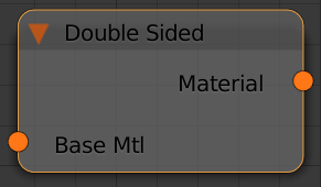
This node will flip the normals for back-facing surfaces with this material assigned.
GLSL
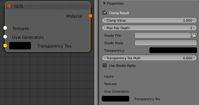 This node can be used to load GLSL shaders (.frag, .glsl files), V-Ray precompiled fragment shaders (.pfrag files) and render them directly with V-Ray.
See the V-Ray GLSL page for more detailed description of the language and examples.
This node is the first stage of the V-Ray implementation of GLSL support. In this version, the shaders are compiled to byte code for a software virtual machine, which is then interpreted. Due to this run-time interpretation, GLSL shaders can be somewhat slower to render than V-Ray shaders written in C++. In future builds of V-Ray, shaders will be directly compiled to machine code for faster rendering.
Clamp Result - determines whether to force the result in the [0, Clamp Value] range or not.
Clamp Value - specifies the upper clamp limit if Clamp Result is enabled.
Max Ray Depth - specifies the maximum reflection/refraction depth for the shader.
Shader File - specifies the .glsl, .frag, or .pfrag file which contains the shader code.
Shader Node - specifies a custom name for the shader node
Transparency - override the alpha if Use Shader Alpha off. You can use either a single color or a texture for that parameter.
Transparency Tex Mult - a multiplier for the Transparency parameter when a texture is used
Use Shader Alpha - use the alpha calculated in the shader.
Material ID
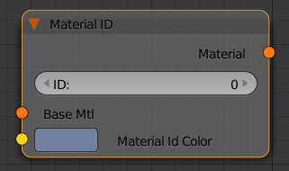
This node allows you to assign an ID number to any material in your scene. This ID can be later to extract a mask for all objects with that material using the MultiMatte render element.
Base Mtl - a slot for the material that the ID will be assigned to
ID - a unique identification number for that material
Multi ID
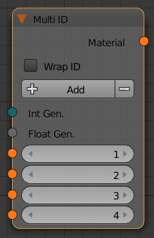 This node allows you to assign different materials on a single mesh based on face IDs.
Override
 This node allows a surface to look different depending on whether it is seen through reflections, refractions, or GI. With this material you can get a fine control over the color bleeding, reflections, refractions, and shadows of the objects.
Environment Priority - this specifies how to determine the environment to use if a reflected or refracted ray goes through several materials each of which has an environment override.
Base - this is the material V-Ray will use while rendering the object.
GI - this is the material V-Ray will use while calculating the GI solution.
Reflection - this is the material V-Ray will use to render the object with, when the object is seen in reflections.
Refraction - this is the material V-Ray will use to render the object with, when the object is seen in refractions
Shadow - this is the material that will be used to render shadows cast from the object.
Environment - this is an environment override for the Base Material
Render Stats
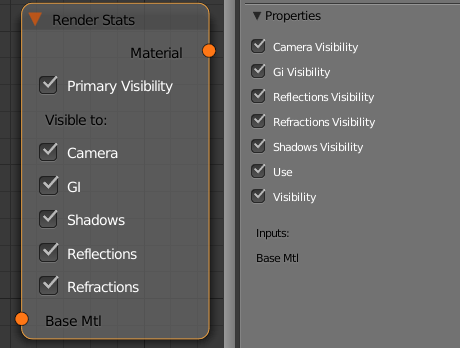 This node allows you to make the object invisible to different rays during rendering.
Primary Visibility (Visibility) - controls the total visibility of the object
Camera - controls the visibility of the object for the camera rays
GI - controls the visibility of the object for GI rays
Shadows - controls whether or not the object casts shadows
Reflections - controls the visibility of the object in reflections
Refractions - controls the visibility if the object in refractions
Use - enables the Render Stats node
Round Edges
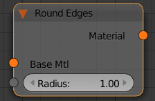 This node uses bump mapping to smooth out the edges of the geometry during render time
Radius - specify a radius (in world units) for the round edges effect. Since the actual geometry is not being changed and only the normals of the faces are affected large values here may produce undesirable effects.
Single
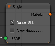 This node is the default material node. It requires that a BRDF node is connected to its input.
Double Sided - if this is checked, V-Ray will flip the normal for back-facing surfaces with this material. Otherwise, the lighting on the "outer" side of the material will be computed always. You can use this to achieve a fake translucent effect for thin objects like paper.
Allow Negative Colors - if this is checked the user can use negative values in the color swatches of the connected BRDF.
Two Sided
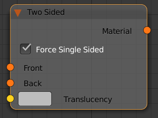 This is a utility node provided with the V-Ray renderer. The material allows seeing the light on the backside of objects. Use this material to simulate thin translucent surfaces like paper, cloth curtains, tree leaves etc.
Front - this is the material which is going to be used for front-side faces as defined by the object normals.
Back - this is the material V-Ray will use for back side faces as defined by their normals.
Translucency - this determines which side (front or back) relative to the camera is more visible in the rendering process. By default this value is 0.5, which means that both the side facing the camera, and the one facing away from it, will be visible to the same degree. When this parameter is closer to 0.0 the more of the material facing the camera is going to be seen. When it is closer to 1.0, the more of the back material is seen.
Force single-sided sub-materials - when is is on (the default), the sub-materials will render as one-sided materials. Turning this option off is not recommended.
VRmat
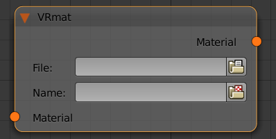 This node allows you to load a material from a .vrmat, .vismat or a .vrscene file
File - a slot for the .vrmat or .vismat file
Name - a slot for the .vrscene file
Wrapper
 This node can be used to specify additional surface properties per material.
Base Material - this is the actual surface material.
Alpha contribution Tex - determines the appearance of the object in the alpha channel of the rendered image. A value of 1.0 means the alpha channel will be derived from the transparency of the base material. A value of 0.0 means the object will not appear in the alpha channel at all and will show the alpha of the objects behind it. A value of -1.0 means that the transparency of the base material will cut out from the alpha of the objects behind. Matte objects are typically given an alpha contribution of -1.0. Note that this option is independent of the Matte surface option (i.e. a surface can have an alpha contribution of -1.0 without being a matte surface).