This page provides information on how to get the most out of Phoenix FD for 3ds Max.
Overview
This page provides tips on a variety of topics to help you get the most out of Phoenix FD.
Changing Paths
Changing the Default Phoenix FD Paths
Phoenix FD saves each simulated frame in a cache file with an *.aur extension, numbered using the frame index. By default, the cache files are put in a folder next to the *.max scene with the same name as the scene and with "_Phoenix FD_frames" appended:

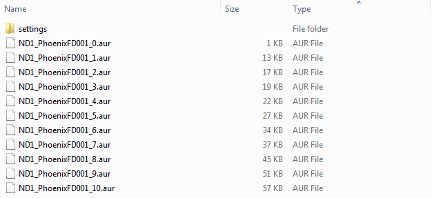
Inside the cache folder, the default names use the simulator's name. For example, a simulator named "PhoenixFD001" outputs these cache files:
You can manually change the output path from the Output rollout. The default paths and file names above are generated using the $(scene_path) macro as an output path, and there are other macros you can use as well, or just manually enter the path you need.
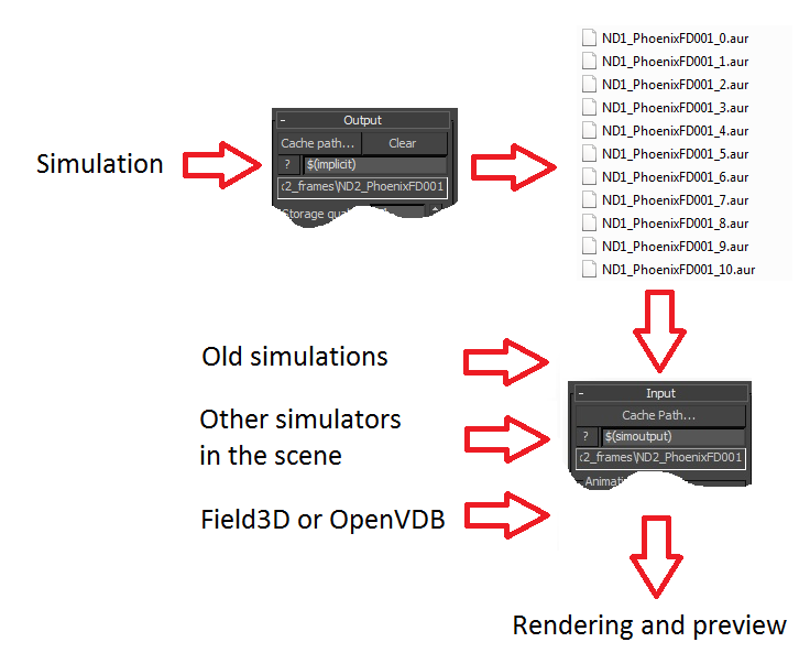
After Phoenix FD has created the *.aur frame cache files, you can preview them in the viewport and render them using V-Ray or the Scanline renderer of 3ds max. By default, Phoenix FD looks for render/preview input files in the $(same_as_output) path, which is the path in the Output Rollout. So even if you change the output manually, the render will keep reading from the new location. You may also manually change the render input path to a series of cache files that you have stored somewhere else previously, or to the cache files of a different simulator in the same scene, or even to a series of *.f3d or *.vdb files exported from other simulation software. Here is the basic flow:
Changing the Default Phoenix FD Paths for Resimulation
Resimulation takes as input a sequence of *.aur, *.f3d, or *.vdb cache files, and processes them in order to improve the grid detail, change the time-scale of the animation, or run a particle simulation again without changing the grid content.
During resimulation, Phoenix FD reads cache files in the Resimulation Input path, performs some of the above operations, and then saves a new cache sequence in the Resimulation Output path.
When resimulation is enabled, the preview and rendering will read from the Resimulation Output Path instead of the render Input.
By default, Phoenix FD reads the files in the $(same_as_output) path, which are already simulated by the regular simulation process, and then saves new *.aur caches in the $(scene_path) path with "_resim" appended at the end of the file name.
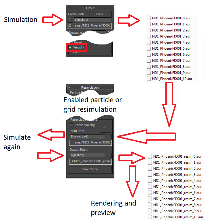
Otherwise, if you enter your paths manually, please make sure that the Resimulation Input resolves to an existing cache sequence with exported Velocity channel (you can check the channels present in a cache file form the Simulation rollout). Also, beware that if the Resimulation Output Path coincides with the Resimulation Input Path, Phoenix FD will not prevent you from overwriting your existing cache files - it's valid to do so if you need a more complicated setup.
Here is the basic resimulation flow:
The following error message may appear when you start a re-simulation:
"Cannot start the Re-Simulation! Please make sure the simulation was run with the 'Velocity' channel checked under the 'Output' rollout, and that the cache files in the Resimulation Input path exist."
The reason may be that either the files in the Resimulation's Input Path do not exist at all, or they do not have velocity exported when you have simulated them beforehand.
Of course, you may use more complicated setups where you resimulate over an already resimulated cache file, or you may Load an existing base cache file as the initial state of the re-simulation. These are all possible, you just need to have velocity in the base cache and an existing path to it.
This topic is regarding fire/smoke resimulation. Liquid resimulation does not use separate path. Instead, it overrides the existing files, because it does not change the channels used as source
Simulating
Units to Use When Simulating
Both the Liquid and the Fire/Smoke simulators work best when the scale of the container matches the real-world size of the simulated effect. You can check the dimensions of the container in the Grid rollout, and also you can check the dimensions of an already simulated cache in the Simulation rollout. If you are simulating a camp fire, your container should be at most a couple of meters wide. Note that it doesn't matter if this is two meters or two thousand millimeters - the way you view the units is irrelevant. Phoenix FD always converts internally the units to a common world-size length, so the only important thing is how big the container is according to the Grid or Simulation rollouts. If you are simulating a volcano for example, the container should be several hundred meters wide, or several hundred thousand millimeters.
Setting up a Simple Smoke / Fire Simulation
For more information of this topic, please see the Phoenix FD QuickStart Guide and the Quick Simulation Setup page.
Setting up a Simple Liquid Simulation
For more information of this topic, please see the Phoenix FD QuickStart Guide and the Quick Simulation Setup page.
Setting up a Network Simulation
Phoenix FD allows you to send a scene for simulation on a different machine using a simple user interface under the Phoenix FD menu, which currently supports submission to Backburner and submission to Thinkbox Deadline. Submitting simulations this way does not require a GUI license for Phoenix FD on the remote machine and will consume only a Phoenix FD Simulation License. It can be useful for offloading simulations to a different machine or a farm while the workstation is engaged. Note that currently Phoenix FD cannot be used to distribute (and speed up) a single simulation over many machines on the network. Instead, several independent simulations or several variations of the same simulation can be run, each on a separate computer.
Simulating Liquid Scenes from Phoenix FD 2.2 or older
If you open а scene saved with Phoenix FD version 2.2 or older, it contains a PHXSimulator which is a combined simulator for both liquids and smoke/fire. The PHXSimulator can no longer be created in Phoenix FD 3.0.
You could convert this simulator to a LiquidSim object by selecting it and typing the following into the MaxScript listener:
a_converttoliquid()
This will allow you to access new features such as Wetting in the Dynamics rollout. Non-liquid options will also be hidden.
Simulation in 2D
The FireSmokeSim has the ability to perform a 2D simulation if one of the grid sizes is set to 1. To keep features like the embedded gravity and pressure decay, it is recommended to leave the Z direction active and set the X or Y size to 1. The main application of this feature is to create very wide fires that would otherwise be difficult with 3d simulation, like the image below.

Fluid Simulations in Hollow Objects
When simulating fluids in hollow objects, please use the FireSmoke ConfineGeometry or the Liquid ConfineGeometry as the bounding volume of the simulation.
Initializing Part of the Grid with Liquid, Smoke or Other Content
Since Phoenix FD 3.0 there is a per object option to start the simulation with the object's volume filled with liquid.
However, this option is not applicable in fire/smoke simulations, because it's not clear what exactly the object must be filled with. For example, you may need smoke, or fuel, or hot/cold air. For fire/smoke simulations, the volume fill must be arranged manually using Volume Brush mode for the PHXSource with Brush Effect set to 100%.
Create a PHXSource helper, and select Volume Brush for Emit Mode. Select the channels that must be filled.
Create a geometry covering the volume that should be filled with the desired channel, and add it as an Emitter Node in the PHXSource's General rollout.
Animate the Brush Effect parameter from 100 in the first frame to 0 in the second frame.
Disable the Velocity checkbox of the LiquidSrc helper, or the fluid may refuse to leave the volume of the emitter.
Moving Geometry vs. Moving Simulator
Some simulations are hard to handle because of moving objects in them (e.g. a fire ball or bottle with liquid). The first, but not the only problem that appears is the need to cover the entire route of the moving object with the simulator object, and this requires really huge amount of cells to get the needed resolution. Even for a novice it's apparent that such simulation is not efficient. The simulation is concentrated in a very small area which is moving in the huge empty grid. But this is not all. In the case of moving a bottle with liquid, you may have a short route that is easy to cover, but you still may have problems because the bottle changes its representation in the grid and each frame it must push the particles inside.
Phoenix FD has a very elegant solutions for such cases - the Inertial forces option within the Dynamics rollout. It binds the simulator to the moving object, and the needed forces will be produced to ensure the realistic fluid response.
Smoke Without the Smoke Channel
This is a technique that can accelerate the simulation up to 20% and decrease the RAM consumption about 10%. It sounds strange, but in some cases you can achieve the exact same look of the smoke without even using the smoke channel in the simulation, thus increasing the performance. How is this possible? The smoke and the temperature are born by the sources and are transported by the velocity field through the grid, mixing themselves with the environment air. This makes the temperature lower and the smoke thinner. It would be correct to assume that if some conditions are satisfied, the temperature and the smoke will have equal temp of decrease, and knowing the temperature, we can predict the smoke. So why do we need to simulate the smoke if we can reconstruct it by the temperature? In a normal fire/smoke/explosion simulation, the smoke channel is only used to calculate the opacity, so you just need a proper temperature-based opacity curve. How do we build it? It's the default curve set for Smoke density when you set Based on to Temperature in the Smoke Opacity rollout. Controlling the opacity is as simple as changing the vertical position of the right point of the curve.
Connecting Two Simulators in a Cascade Setup
There are many situations when the simulation area is narrow and its volume is not very large by itself, but for some reason its bounding box is big and requires a huge grid to cover it. A perfect example for such a situation is a waterfall - the upper area can be covered by a box, which is wide, but not very tall; the vertical area can be covered by a tall and not very wide box; but together they have to be covered by a box that is both wide and tall, so a large grid has to be simulated for only a small significant volume. Another such example is the Wine Sample Scene.
For liquids, Phoenix FD provides very easy way to do this. You have to simulate first the source simulator, and afterwards start the recipient simulator. The recipient simulator must link to the source simulator through the Cascade Source parameter in the Grid rollout of the LiquidSim.
For smoke/fire, the ability to put a Phoenix FD simulator as a source for another one is used. When a Phoenix FD object is used as a source, the implicit surface is determined by the Surface channel in the Rendering rollout, the Isosurface Level defines the geometry surface, and the new born fluid will appear over it. You have to set the isosurface level to a very small value, thus making the source surface a box. To avoid the additional speed added by the discharge parameter, in the PHXSource rollout, use either the Volume Brush for the Emit Mode with Brush Effect set to 100%, or use Volume Inject mode with a very low Outgoing Velocity (e.g. 0.001). Do not make it zero, because the system will decide that this is not a source and will skip it. To transfer the parameters of the gas from the first simulator to the second one, import the used channels of the first simulator into the map slots of the source helper using a Grid Texture. As the simulation will usually be ran multiple times, to avoid backward interferences, add the second simulator in the exclude list of the source simulator.
Slowing Down a Simulation, Animating the Time-Scale, etc.
Phoenix FD has many tools for changing the animation timing of a cache sequence after it is simulated. The Input rollout has a variety of animation controls in the Time Bend section where you can change the speed of the animation, loop, or directly animate the cache index for each timeline frame. When using these controls, Phoenix FD often needs to internally blend between two cache files to produce a given frame on the timeline. The Time Bend Controls blend cache files on the go, at the moment when a new frame is loaded on the timeline - either while you're previewing the simulation in the viewport, or when rendering. For fire/smoke simulations, if you don't want this slowdown, you can bake a new sequence of re-timed caches using Time Bend Resimulation, as described below.
For liquids, simply changing the Input rollout Time Bend controls is enough to re-time a simulation.
For fire/smoke, you can first try the Time Bend controls using the fast 'Interpolate' Frame Blend method, or if you have Velocity and Advection Origin grid channels saved in the cache files, you can get much better looking results using the Precise Tracing Frame Blend method. However, if you do have fire in the setup, it might flicker after re-timing using the Time Bend controls. If you see any flickering/jittering/ghosting effects, you can run a Time Bend Resimulation to get smoother playback. The procedure is as follows:
Enable Velocity export in the Output rollout. This channel is necessary for resimulation.
Simulate your base simulation.
When the simulation finishes, you can adjust your Time bend controls from the Input rollout. You can change your play speed, set it to loop mode or animate the play speed using the direct cache index mode.
Do not change any settings in the Dynamics rollout if you want to get a correct Time Bend Resimulation. You can experiment, of course, but results will typically have flickering or distorted playback.
From the Resimulation rollout, enable Grid Resimulation and enable Use Time Bend Controls. You can increase the Amplify Resolution or leave it at 0. You can also add wavelet turbulence, if the Wavelet channel was exported in the base simulation.
If Play speed in the Input rollout is a constant value, use 3ds Max's 'Re-Scale time' option to stretch the animations in the scene so that they match your speed. If you want a Play Speed of 0.2, scale the scene time 1/0.2 = 5 times.
You can choose between two methods of Time Bend in the Resimulation rollout depending on the result you need. Note that both methods work best for simulations with Steps Per Frame set to a value of 1:
The General-Purpose method can deal with all kinds of play speeds - both above and below 1, as well as playing backwards. This method runs fast, but may produce some flickering or motion jitter;
The Slow Down method works well only when your play speed is between 0 and 1, but will provide smooth playback without jittering or flicker. This method may produce more dissipation, so it's good to combine it with Multi-pass advection for fire/smoke.
Disable all unused output channels before starting the Resimulation from the No-Export Channels option in the Resimulation rollout. This will reduce the cache file size and speed up the resimulation.

Input Play Speed = 0.2, Interpolation Blend
Slow Down method + Wavelet
General-Purpose method + Wavelet
Why is the cache file for every 15th frame larger than the rest?
These are the Backup Frames Phoenix FD uses when you press Restore on the Simulation rollout. In order to restore a stopped simulation, the simulator needs all the simulation data, so these cache files contain all the internal simulator data - velocities, particle IDs, etc. and thus they are larger. You can control how often such frames are written to cache from the Output rollout's Backup Interval option. By default the Backup Interval is set to 15 frames, and if you don't intend to Restore the simulation later, you can turn this off by setting it to 0, so you can save some hard drive space.
Why do I have random exploding liquid jets in my FLIP simulation?
If you have random liquid particles exploding during the simulation, please check your geometry. In order for all meshes interacting with the simulation to behave without issues, they must follow these rules:
- The geometry must be "water-tight". This means that the geometries interacting with the simulation must have a volume. If you imagine you fill that mesh with water, it won't spill out. It must not be a plane or a deformed one-sided sheet of geometry and it must not have holes in it. In 3ds Max the easiest way to fix this is to apply a Shell modifier on the geometry.
- The geometry must not have flipped normals.
- The geometry must not self-intersect or have overlapping faces.
Rendering
Distributed Rendering
A common problem when setting up DR is that by default Phoenix FD looks for the cache files in the same directory as the scene file using the $(scene_path) keyword. However, at the start of a network render, the scene file is copied to all render machines on the network to a new location, e.g. C:\Users\user\AppData\Local\backburner\Jobs\, while cache files are not automatically sent to the host machine. The cache files are not sent because on one hand they may be really huge and may overload the disk space of the host, and also because in many cases not all of them are actually used in the rendering. This is why when the rendering begins, if the hosts are looking for the cache files in the same directory where the scene file is, the cache files won't be found.
The solution is to move the cache sequence to a shared folder on the network or a mapped network drive and set its path in the Input rollout, using a network-visible UNC input path (a path that starts with \\). You can also browse from the Input rollout's path options.
If you are not using a UNC path, and instead your path points to a drive on your local computer, or is one of the Phoenix FD keywords ($(scene_path), $(scene_dir), etc...), you will receive a message that states "You are using local machine Input path with distributed rendering!".
For more details, please see the docs page dedicated to Distributed Rendering.
Shading particles by Age, Speed, Position, or by their particle color channel
A single Particle Shader, by default, shades all selected particle systems using the same color.
In Phoenix FD 3.10, we added a Color Map slot you can use to color the particles differently, but it can do so much as a texture allows it to - e.g. a checker won't be too much of a interesting shading, and furthermore, it won't change with time, and even if you animate it, it still won't fit the particle movement. However, you can plug a Phoenix FD Grid Texture in the Color Map slot - this way the particles from a Phoenix FD simulation can read voxel data from the grid channels, such as Speed or RGB.
In Phoenix FD 3.11, we extended the Phoenix FD Particle Texture so particles can be shaded using their own channels. Before, what the Particle Texture could do was to take the particle positions and create white areas around each particle in 3D space on a black background. Since Phoenix FD 3.11, the Particle Texture can color the areas around each particle using a color from a particle channel - e.g. the Age, Position, Speed, or even just the particle RGB. This way you can plug the Particle Texture into the Particle Shader's Color Map slot and shade the particles that way.
Rendering with an External Volumetric Shader
Phoenix FD is able to export its content as a texture (see Grid Texture). This makes it possible to use an external volumetric shader for the rendering, such as the VRayEnvironmentFog.
Simple setup for V-Ray environment fog:
Disable (do not delete it!) the Phoenix FD atmosphere from the Environment dialog.
Create a VRayEnvironmentFog atmosphere.
Create a Box gizmo (Helpers > Atmospheric Apparatus) and make its size the same as the Phoenix FD grid.
Add the gizmo to the "Gizmos" list of VRayEnvironmentFog.
Create three PhoenixFDGridTex textures for each element (emissive, diffuse and alpha) and select Object XYZ as coordinate source.
Select the textures in the corresponding slots of the VRayEnvironmentFog.
Set the fog distance to the same value as the Cell size of Phoenix FD, this will produce the same transparency.
Nightly Simulation and Rendering
Most simulations require long time to calculate and it's very convenient to let them run during the night. However, you still have to render the result in the morning and this also consumes a lot of time. The Phoenix FD scripting system allows you to execute any action at the end of the simulation, and that includes the rendering as well. You just have to enable the scripting from the Simulation rollout and open the script text.
Rendering the animation after the simulation has ended
There is a function OnSimulationEnd. Find it and remove the "--" symbols in front of the line that says "max quick render" to enable it. This action is equivalent to pushing the quick render button (F9), so you have to prepare the render settings beforehand. Remember to delete any previous output sequence of images, otherwise a prompting dialog will appear asking if you want to overwrite the files, and the rendering won't start automatically:
fn OnSimulationEnd=(
-- Will be executed once when simulation ends
-- Uncomment the line below to start rendering after the simulation is finished!
  max quick render
)
Render each frame immediately after it was simulated
Using this MaxScript, when you run a Phoenix FD simulation, once a new frame is simulated, it will be immediately rendered and saved to a file.
This way, if you leave a long simulation to run unattended, you can find a ready image sequence waiting for you when you come back, even if the simulation has not finished.
In the Simulator's Simulation rollout, enable Use Script and open the Simulator's MaxScript editor using the Edit... button. In the OnNewFrame function, uncomment the contained code by deleting the " /* " symbols.
Then you have to provide a path to save the ready frames, like in the following code:
fn OnNewFrame=(
-- Will be executed after every new frame
-- Uncomment the code below to render each frame after it is simulated

	rendTimeType = 3
	rendStart = currentTime
	rendEnd = currentTime
	rendSaveFile = true
	rendOutputFilename = "D:/folder1/folder2/frame.jpg"
	max quick render--*/
)
Rendering Phoenix FD together with VRayAerialPerspective, VRayEnvironmentFog or VRayVolumeGrid on V-Ray CPU
With V-Ray CPU, Phoenix FD's shader for fire and smoke and Phoenix FD's Particle Shader both work as a 3ds Max atmosphere by default. Atmospheres are rendered one over the other, so you might get renders where objects appear misplaced or rendered in the wrong depth order if you mix Phoenix FD with other volumetric effects.
If you have volumetric effects in your scene such as an Environment Fog, an Aerial Perspective or a Volume Grid, V-Ray CPU won't be able to properly determine their positions along the camera rays. Consequently, these effects will render as if they were placed one after the other in the camera frustum.
To resolve this problem, you could switch the volumetric rendering mode to Volumetric Geometry for Fire / Smoke, and respectively for particles you could enable Render as Geometry in the Phoenix FD Particle Shader. This will allow V-Ray CPU to properly blend your Phoenix FD simulation with the rest of the volumetric effects in your scene. Note that in these modes you might have to increase the V-Ray Max Transparency Levels option in the Global Switches V-Ray tab.
Importing and Rendering Simulations from FumeFX and Houdini
Phoenix FD can import Field3D (*.f3d) and OpenVDB (*.vdb) cache files that other fluid simulators have simulated and exported. This way you can render them with Phoenix FD's shader and make use of Phoenix FD's special features.
Field3D files which come from FumeFX must be exported with gzip compression! If they are exported with the default proprietary FumeFX compression, they will not be imported properly in Phoenix FD.
Note that you may import not only atmospheric simulations, but Houdini liquids as well. You can also create a Phoenix FD Ocean using such caches, as long as the liquid touches the sides and the bottom of the container.
The procedure is as follows:
- Create a FireSmokeSim or a LiquidSim object in your scene. The grid size is not important because the imported cache files will override it.
From the Input rollout click the Cache Path... button and pick any file of your sequence and the entire sequence will be loaded. You can also manually type in the format of the sequence using format specifiers for the frame number. Phoenix FD supports the following frame number formats types:
#: frame 1 becomes "1", frame 10 becomes "10", frame 1000 becomes "1000";
##: frame 1 becomes "01", frame 10 becomes "10", frame 1000 becomes "1000";
####: frame 1 becomes "0001", frame 10 becomes "0010", frame 1000 becomes "1000";
etc.

%d: frame 1 becomes "1", frame 10 becomes "10", frame 1000 becomes "1000";
%4d: frame 1 becomes "⋅⋅⋅1", frame 10 becomes "⋅⋅10", frame 1000 becomes "1000";
%04d: frame 1 becomes "0001", frame 10 becomes "0010", frame 1000 becomes "1000";
etc.

<frame>: frame 1 becomes "1", frame 10 becomes "10", frame 1000 becomes "1000";
<frame4>: frame 1 becomes "⋅⋅⋅1", frame 10 becomes "⋅⋅10", frame 1000 becomes "1000";
<frame04>: frame 1 becomes "0001", frame 10 becomes "0010", frame 1000 becomes "1000";
etc.
- Phoenix FD will ask you if you'd like to load a predefined render preset. The presets Phoenix FD comes with are to be used as starting points when importing a foreign cache.
- By that time you will be able to see a preview of the cache in the viewport, and you will also be able to check which grid channels are loaded under the Simulation rollout, in the Cache File Content list.
- In case you want to render using motion blur, or resimulate over the imported cache, you must have the velocity channel exported as well. You can scale the motion blur velocities if needed, by adjusting the Motion Blur Multiplier parameter in the Rendering rollout.
Manually equalizing render settings with FumeFX
There are some important settings to look out for to keep rendering times short:
Make sure the Step% size of Phoenix FD matches the corresponding FumeFX step parameter. A smaller step size will lead to longer render times.
In the Fire rollout, select Fuel as the Based on channel. This is FumeFX's Fire channel after importing the .f3d file. Choose Use Own Opacity for the Fire Opacity Mode and carefully duplicate the fire color and fire opacity diagrams from FumeFX.
Please note that Phoenix FD does not support the Fluid Mapping option from FumeFX.
Phoenix FD has the option to illuminate other objects in the scene automatically by using emissive lights. This will increase the render time. In order to turn it off and keep only the illumination on the volumetric itself, set the Light Power multiplier to 0.0 or 0.001 and use Grid-based Self-Shadowing. You can speed up the "Calculating self-illumination" step using the Reduce Grid option.
Supported channels
Phoenix FD supports the following channels:
Temperature/Liquid
Smoke
Velocity
Speed
RGB
Fuel
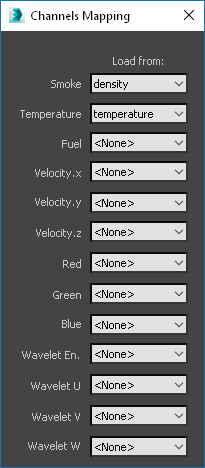
Different applications use different channels and names for them. When loading f3d/ vdb files, Phoenix FD tries to automatically make the conversion to the supported channels. If a channel is not mapped by default, you can manually set it to a channel from the ... button next to the Input Path, by choosing 3rd Party Channel Mappings. Note this option is only accessible when a 3rd party cache file is loaded (non-.aur).

Exporting Alembic files from Phoenix FD meshes from 3ds Max and rendering them with motion blur
Phoenix FD's meshes, just like any other fluid or procedurally generated meshes, change their vertex count on each frame of the animation. This is why the regular motion blur that renderers apply to moving or deforming geometries cannot work for Phoenix FD mesh files. Instead, renderers need the velocity of each vertex from the mesh in order to motion blur it. Inside 3ds Max, Phoenix FD communicates with the renderer directly and provides the vertex velocity when needed. This vertex velocity needs to be exported together with the mesh data when writing Alembic files from Phoenix FD fluids.
In order to export vertex velocity into Alembic files from a Phoenix FD mesh, so you can render them with motion blur, you need the following:
- 3ds Max 2019 or newer.
- Phoenix FD 3.12 build from 8 Dec 2018 or newer.
- In Phoenix FD, you need either:
- a simulated Phoenix FD cache sequence with exported Grid Velocity in the Output rollout;
- an imported cache sequence with velocity channel, which is remapped to the Phoenix FD Velocity.x/y/z channels via the Input -> 3rd Party Channel Mappings dialogue.
- In the Preview rollout, you need to enable 'Show Mesh'.
- In the Export rollout, you need to set 'Export as' to 'Mesh'. Don't forget to revert it to 'Disabled' after you have finished exporting.
- In 3ds Max's Alembic Export Options dialogue, you need to set 'Extra Channels' to 'UVW'.
In 3ds Max, while you have 'Export as' set to 'Mesh', the vertex velocity is in Map Channel 2 of the mesh, named 'velocity'. 3ds Max's built-in exporter names the Color Set in the exported Alembic file 'Max_Map_Channel velocity'.
Importing the Alembic file back into 3ds Max via the 3ds Max built-in Alembic importer requires you to set the 'Velocity channel' to 2 in the V-Ray object properties dialogue, so you can render it with motion blur using V-Ray.
Importing the Alembic file in any host via VRayProxy will render with motion blur without any additional adjustments. It requires V-Ray Next Update 1.1, or newer.
Importing the vertex velocity of the Alembic file into Maya using Maya's native importer (Cache -> Alembic Cache -> Import Alembic) is not supported.