The Plane, Disc, and Sphere are each a type of VRayLight with similar options.
Overview
Plane, Disc, and Sphere lights are types of VRayLight objects. These are good general-purpose V-Ray lights for lighting scenes to simulate real-world light sources like lamps and ceiling lights.
Create menu > Lights > V-Ray > V-Ray Plane/Sphere Light > Click and drag in a viewport
||Create panel|| > Lights > Choose V-Ray from dropdown > VRayLight > Click and drag in a viewport
Sample Uses
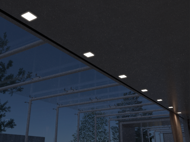
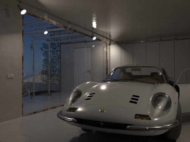
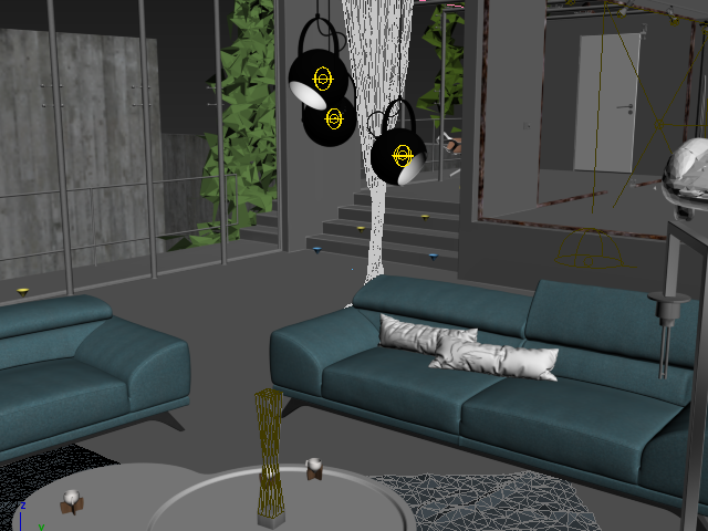
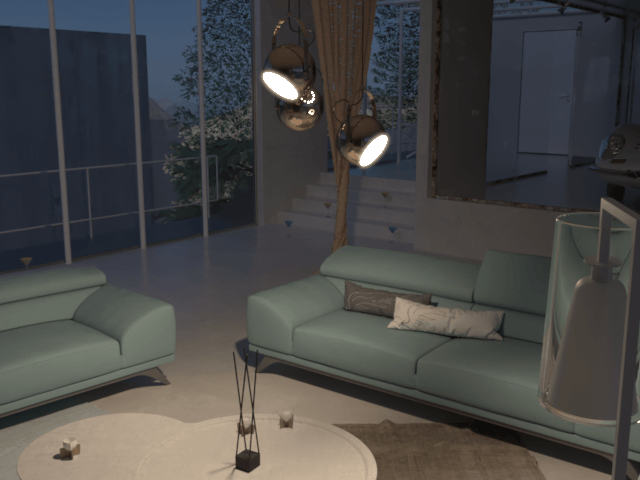
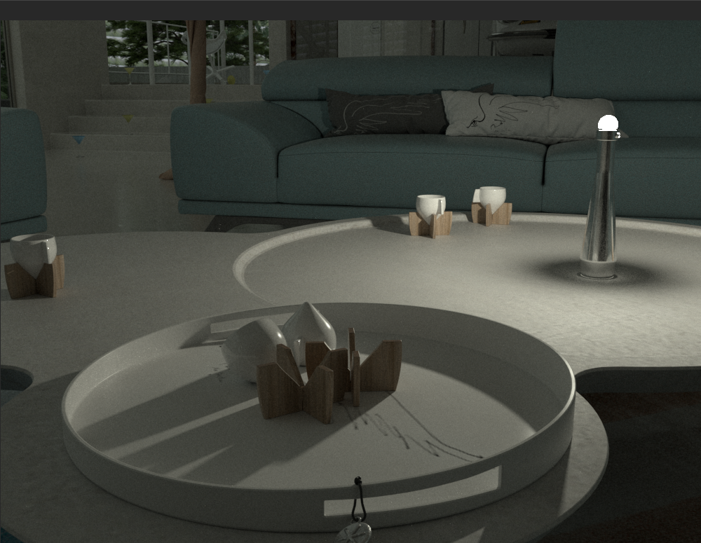
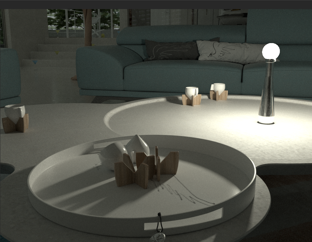
By default, V-Ray will render the light source if it is seen in the camera, as shown in the examples below. To render without seeing the light source, enable the light's lnvisible option.
Note: When a Plane, Disc, or Sphere light is visible in the rendering, aliasing at the edges of the light source can occur. Lens Effects such as the Bloom Effect (as used in the example images below) and Glare Effect are one way to hide the aliasing, while another is the use of a VraySoftBox map. For information on the cause of the aliasing and solutions for it, see Notes below.
Parameters - General Rollout
On – Turns the VRayLight on and off.
Type – Specifies the shape and function of the light:
Plane – The VRayLight takes the shape of a planar rectangle.
Sphere – The VRayLight has the shape of a sphere.
Dome – The VRayLight emanates from a spherical or hemispherical dome around the scene extents. See the Dome Light page.
Mesh – Allows the usage of any mesh object as the shape of the light. See the Mesh Light page.
Disc – The VRayLight takes the shape of a planar disc.
Targeted – When enabled, a separate target object is attached to the light source. This target object can be moved separately from the light source, making it easier to point the light within the scene. The value specifies the distance from the light source to the target. While any type of VRayLight can have a target, the target is truly useful only with Plane and Disc lights. This option can be changed only on the Modify panel.
Length – The length of a Plane light source, measured in scene units.
Width – The width of the Plane light source, measured in scene units.
Using the length, width or V size parameters is the recommended method for controlling the light's size. Avoid scaling the light. Uniform scaling can be used when the scene needs to be scaled up or down, but non-uniform scaling produces skewed or elliptical shapes, which may produce incorrect results.
Radius – The radius of the Sphere or Disc light source, measured in scene units.
Note: The size of the light source sometimes affects the light's intensity, shadows, and light diffusion depending on what is selected for the Units parameter. For more information, see Example: Light Units, Light Size and Shadow Crispness.
Units – Specifies the light units. Using correct units is essential when you work with the VRayPhysicalCamera. The light automatically takes the scene's unit scale into consideration to produce the correct result for the scale you are working with. The possible values are:
Default (image) – The color and multiplier directly determine the visible color of the light without any conversion. The light surface appears with the given color in the final image when seen directly by the camera (assuming there is no color mapping involved).
Luminous power (lm) – Total emitted visible light power measured in lumens. When this setting is used, the intensity of the light does not depend on its size. A typical 100W incandescent light bulb emits about 1500 lms of light.
Luminance (lm/m²/sr) – Visible light surface power measured in lumens per square meter per steradian. When this setting is used, the intensity of the light depends on its size.
Radiant power (W) – Total emitted visible light power measured in watts. When using this setting, the intensity of the light does not depend on its size. Keep in mind that this is not the same as the electric power consumed by a light bulb for example. A typical 100W light bulb only emits between 2 and 3 watts as visible light.
Radiance (W/m²/sr) – Visible light surface power measured in watts per square meter per steradian. When this setting is used, the intensity of the light depends on its size.
Multiplier – Multiplier for the light color, and also the light intensity for some Units settings.
Mode – Specifies the mode in which the color of the light is determined:
Color – When this option is selected, the Color swatch specifies the color of the light rays and of the light source itself when visible in renderings. For Units settings other than Default (image), this color is normalized so that only the color hue is used.
Temperature – When this option is selected, the color of both light rays and the light source itself is specified by the Temperature value expressed in Kelvin.
Texture – Enables the use of a texture for the light surface when a Plane or Disc light type is used. The button under this option selects the map to use. The texture intensity is also affected by the Multiplier value.
Res – Specifies the resolution at which the texture is resampled for importance sampling.
Example: Light Source Size and Shadow Crispness
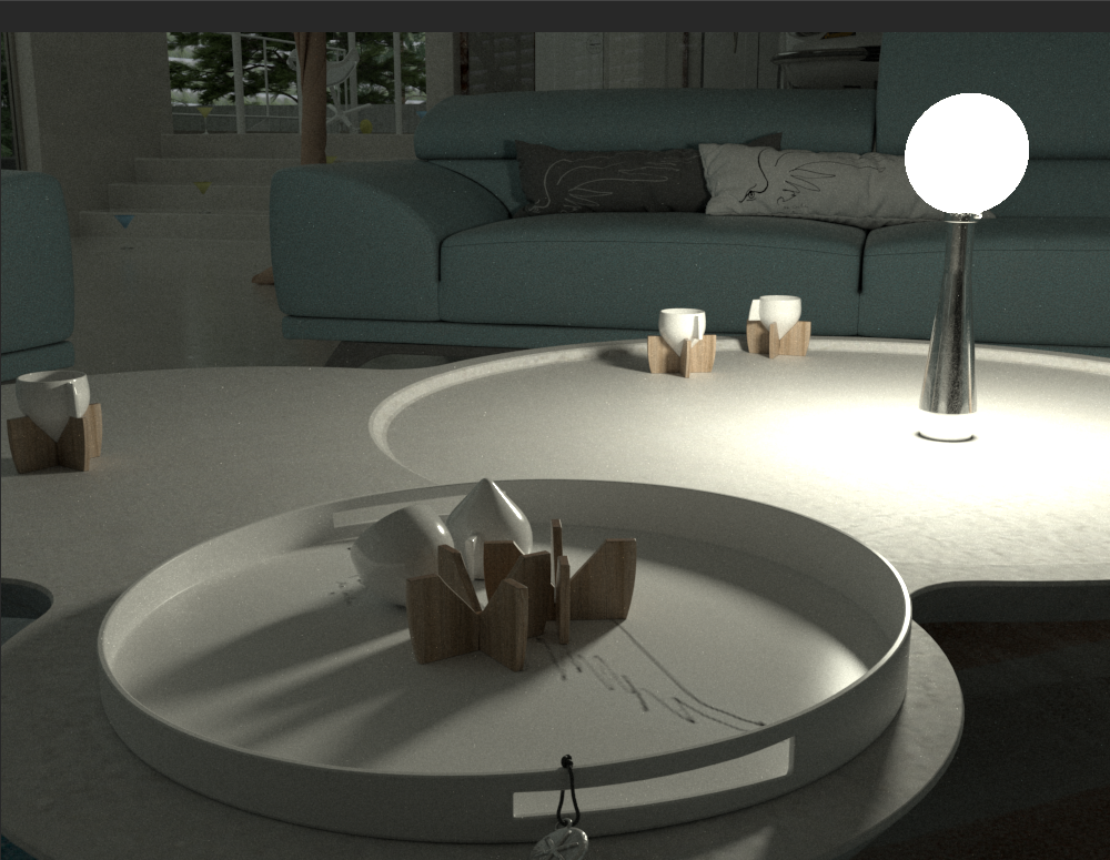
The following images show how the size of a Sphere light source affects shadows. Larger light sources produce blurrier shadows, while smaller light sources produce sharper shadows:
Radius = 0.5; Units set to Luminous power (lm)
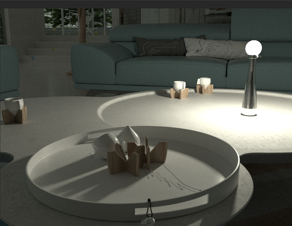
Radius = 1.0; Units set to Luminous power (lm)
Radius = 2.0; Units set to Luminous power (lm)
Example: Light Size and Intensity
In the previous example, the light emitted by the light in all images is of the same intensity regardless of the light source's size. This is because the light's Units were set to Luminous power (lm), which doesn't depend on the light source size for intensity. Both the Luminous power (lm) and Radiant power (W) settings allow the light source to retain the same intensity regardless of the light source's size.
The same is not true for other Units settings. With the Default (image), Luminance (lm/m²/sr) and Radiance (W/m²/sr) settings, the light's intensity is directly affected by the size of the light source.
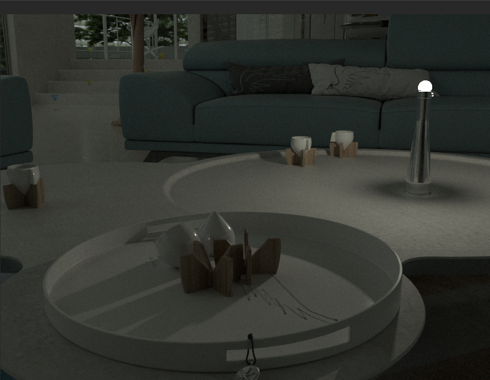
Radius = 0.5; Units = Default (image)
Radius = 1.0; Units = Default (image)
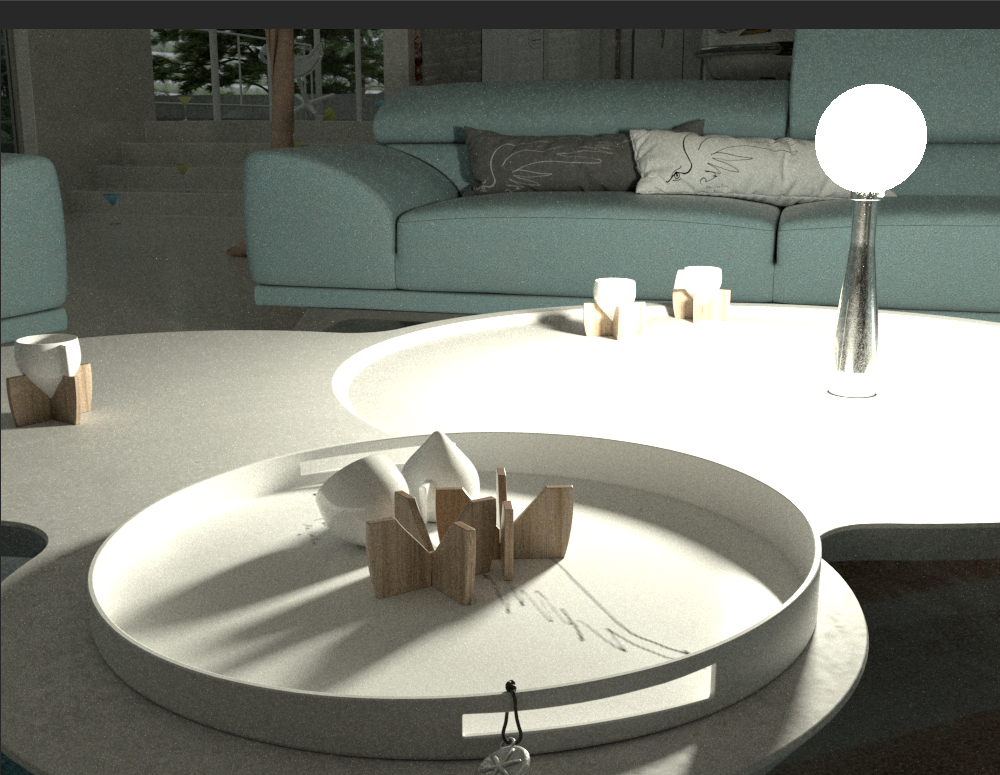
Radius = 2.0; Units = Default (image)
Parameters - Rectangle/Disc Light Rollout
This rollout is only available when the Type is set to Plane or Disc.
Directional – By default, the light from the Plane or Disc light is spread out equally in all directions on the side in which the light points. As this parameter is increased toward a value 0f 1.0, the spread narrows, making the light more directional. A value of 0 (default) the light shines in all directions around the light source. A value of 0.5 pushes the light cone to a 45-degree angle, and a value of 1.0 (maximum) makes a 90-degree light cone. For more information, see the Directional Spread example below.
Preview – Allows the light's spread angle to be seen as a wireframe in the viewport, as it is set by the light's Directional parameter.
Always – The preview is always displayed.
Selected – The preview is displayed only when the light is selected.
Never – The preview is never displayed.
Preview texmap – If a texture is used to drive the light, enabling this shows the texture in the viewport. This option is grayed out if your 3DS Max viewport is configured to use Nitrous viewport driver. To enable, switch to the direct3D viewport.
Example: Directional Spread
The Directional parameter controls the spread of the Plane or Disc light. A value of 0 produces the maximum spread of light in all directions as seen below left, while a value of 1 creates a narrow 90-degree cone of light as seen below right.
Plane light with Directional = 0, 0.5, 1.0
Preview = Always
The following example shows the effect of the Directional parameter. Note that the plane light itself appears to turn black as the value gets closer to 1.0. This is due to the simplified directional distribution. The light is forced only in the forward direction, so the plane appears dark when viewing it from the side. This phenomenon does not occur with real-world lights because they exhibit more complex directional distribution.
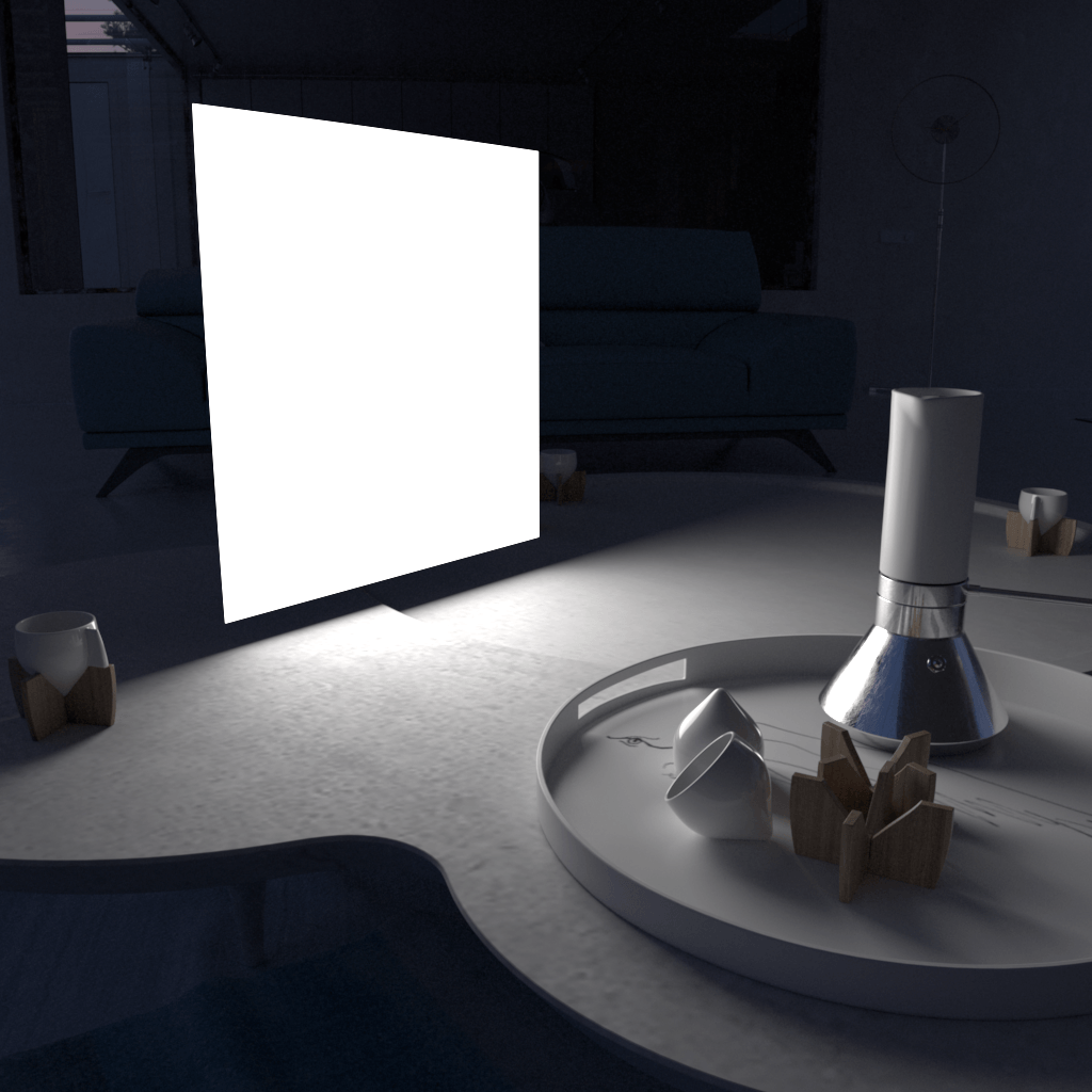 Directional = 0.0
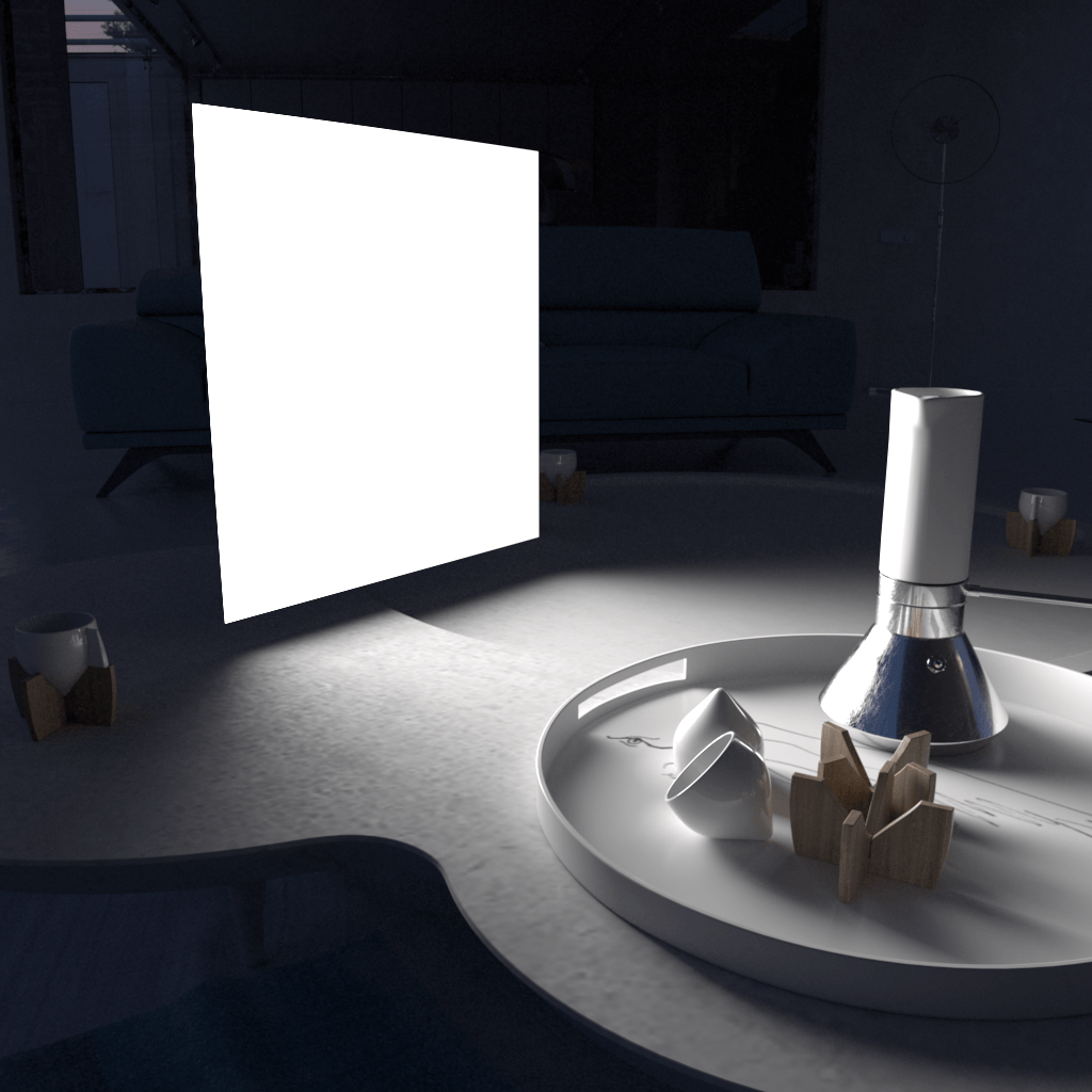 Directional = 0.6
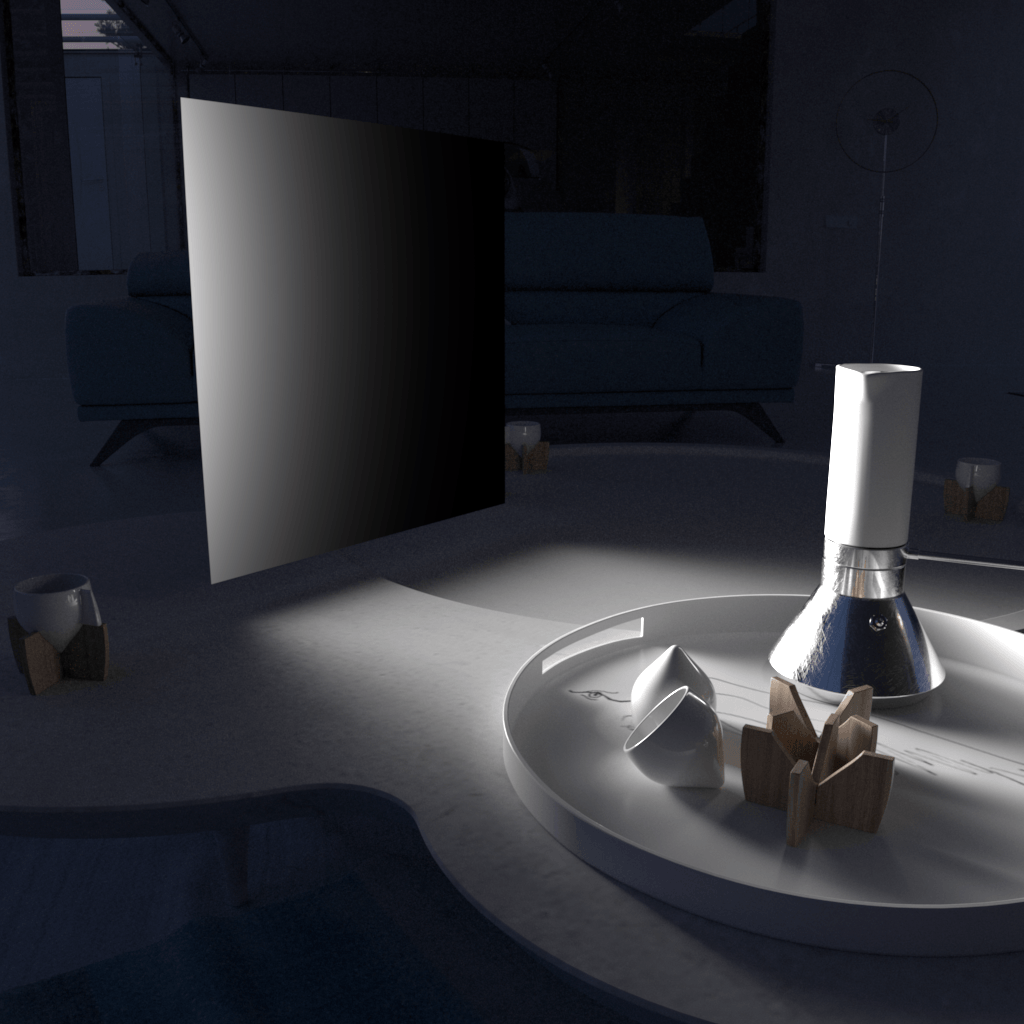 Directional = 0.8
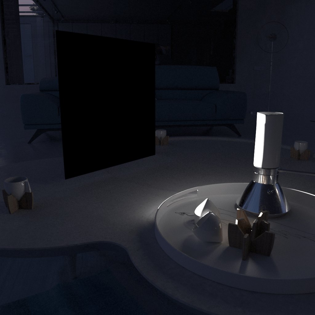 Directional = 1.0
Parameters - Options Rollout
Exclude – Opens the 3ds Max Exclude/Include window for selection of objects to be excluded or included in illumination and/or shadow-casting for this light.
Cast shadows – When enabled (the default), the light casts shadows. Turn this option off to disable shadow casting for the light.
Double-sided – When the light is a Plane or Disc type, this option controls whether light is beamed from both sides of the light icon. This field has no effect for Sphere type of light source. For more information, see The Single-Sided vs Double-Sided Lights example below.
Invisible – Controls whether the shape of the light source is visible in the rendered image. When this option is disabled, the light source is rendered in the color specified by the Color or Temperature setting in the Intensity rollout. This option only affects the visibility of the light when seen directly by the camera or through refractions. The visibility of the light with respect to reflections is controlled by the Affect reflections option.
Note: Regardless of whether this option is enabled, the light source is still taken into account by Global Illumination calculations, which might cause secondary GI rays to be blocked by or bounced off the light's surface. To make the light completely invisible to GI, place a VRayColor texture map into the light's texture slot and set the alpha value for the VRayColor map to 0.0.
No decay – Normally the light intensity is inversely proportional to the square of the distance from the light (surfaces that are farther from the light are darker than surfaces which are closer to the light). When this option is enabled, the intensity does not decay with distance.
Skylight portal – When enabled, the light behaves as a portal or conduit for the environment behind it. As an example, this option is appropriate for an interior daytime scene, where a Plane light source could be placed in a window opening and directed toward the inside of a room. If the Skylight portal option is enabled for such a light, the light and color from the scene outside the window (including the environment map and any rendered objects) flows directly through the window opening and into the room. While an interior daytime scene is often sufficiently lit by a bright environment and GI alone, the Skylight portal option can be used to augment or brighten such lighting. With this option, the light takes its intensity and color from the environment behind it rather than from the Color and Multiplier parameters. For more information, see The Skylight, Self-Illuminated Panels, and VRayLights example below.
Simple – Available only if the Skylight portal option is enabled. When this option is enabled, the portal only uses colors from the environment map and not from any scene objects behind the portal. When this option is disabled, the portal light takes its color from both the environment map and objects behind the light source. If this option is disabled, the light traces additional rays to render the objects, which might slow down the rendering. Enabling this option makes the rendering of portal lights faster.
Store with irradiance map – When enabled and Irradiance map is used as a GI engine, V-Ray calculates the effects of the VRayLight and stores them in the irradiance map file. The result is that the irradiance map is computed more slowly but the rendering takes less time. You can also save the irradiance map file and reuse it later.
Affect diffuse – Determines whether the light affects the diffuse portion of the materials. The value controls the light's contribution to the diffuse portion of the materials.
Affect specular – Determines whether the light affects the specular portion of the materials. The value controls the light's contribution to specular reflections.
Affect reflections – Specifies whether the light source appears in reflections.
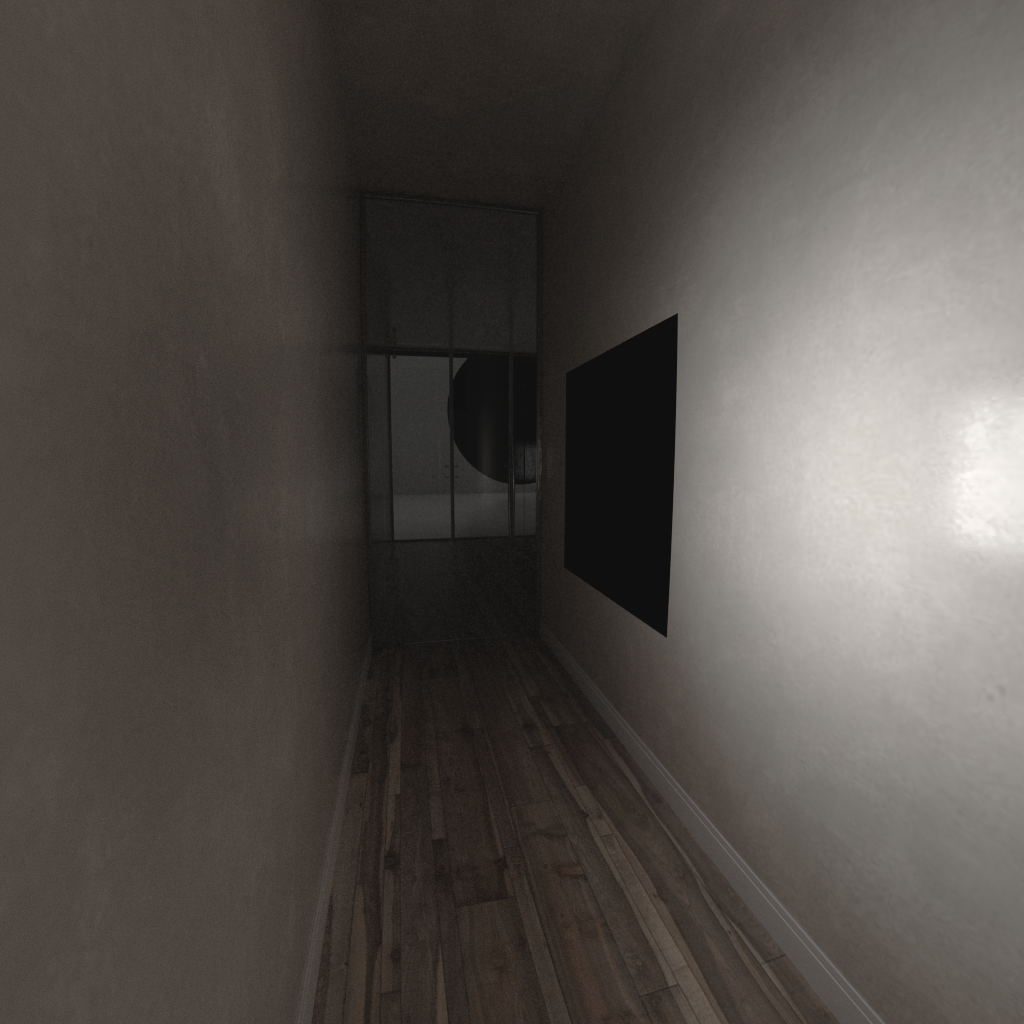
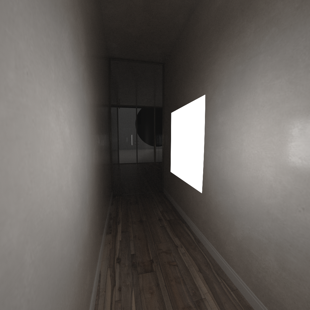
Example: Single-Sided vs Double-Sided Lights
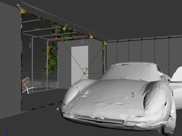
This example demonstrates how a Plane light is affected when the Double-sided option on the Options rollout is enabled or disabled. The light is pointed away from the hallway.
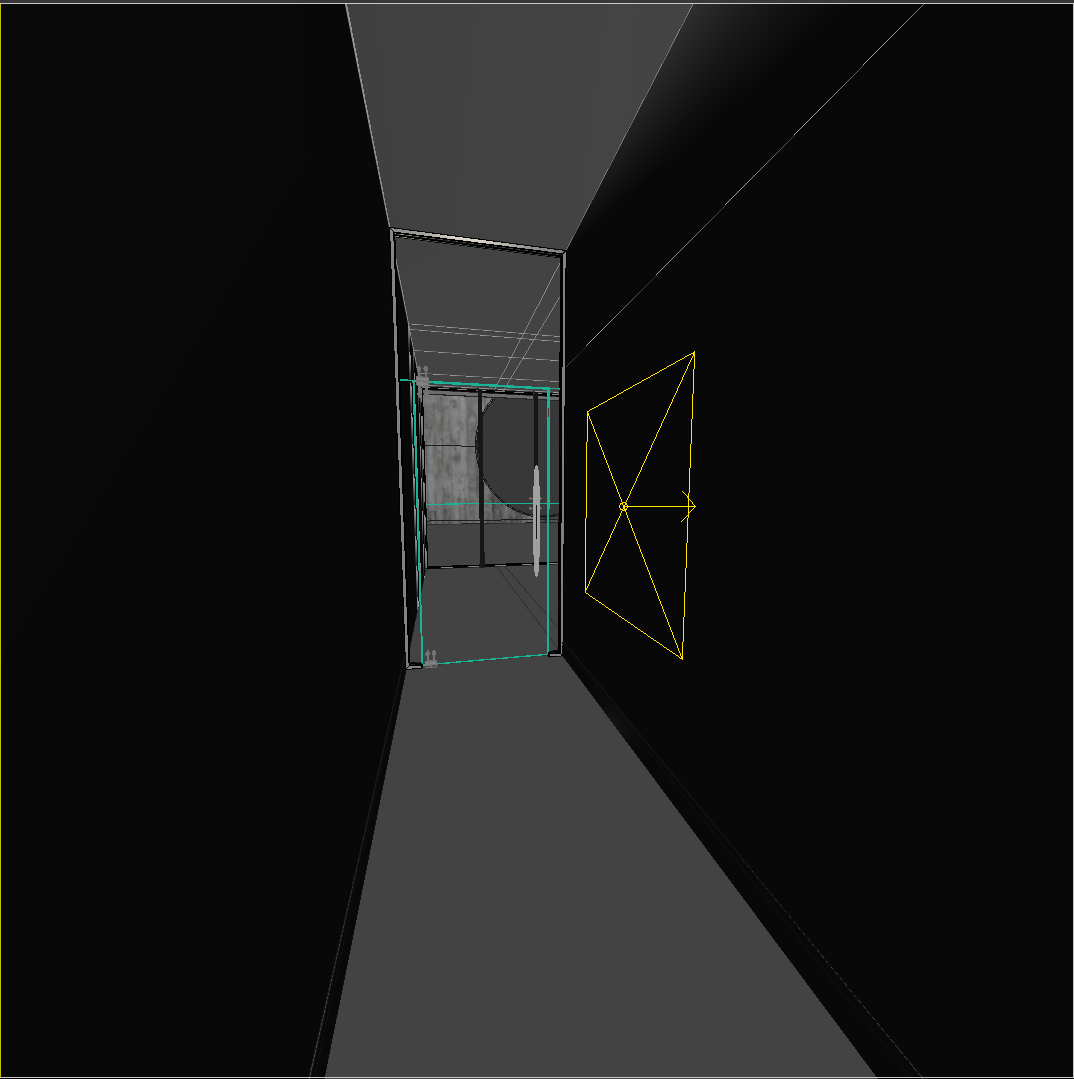
The VRayLight in the viewport.
Example: No Decay vs. Real-World Light Behavior
The following images demonstrate the use of the No decay setting on the Options rollout. In the real world, light attenuates with the inverse square of the distance from the light to the shaded surface. The settings for the light source are the same for both images with the exception of the No decay setting:
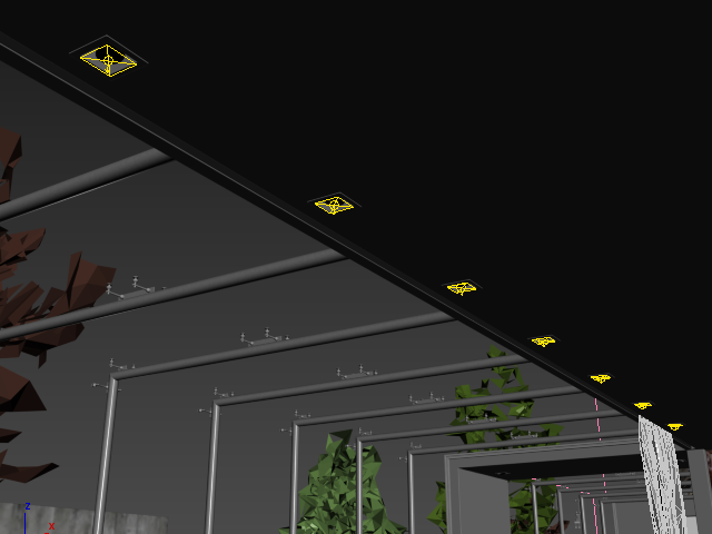
Example: Skylight, Self-Illuminated Panels, and VRayLights
Here is an example of a simple room where the light comes from the environment. The scene was rendered in several different ways with GI enabled and using Progressive mode to achieve the same quality level:
- With a plane light with simple Skylight enabled allowing in light from the environment behind it
- With a 3ds Max Plane object at the window that has a VRayMtl assigned to it with the Self-Illumination color set to white and the GI option enabled
- With a Plane light at the window
In all cases, Brute Force was used as the primary GI engine and Light cache was used as a secondary GI engine. The environment, the self-illuminated panel, and the Plane light all have the exact same color and multiplier.
Skylight only
Render Time: 1m 37.8s
Self-illuminated panel at the window
Render Time: 1m 46.6s
Plane light only
Render Time 0m 18.2s
As you can see, all methods produce almost exactly the same light distribution, but there are differences in render times to achieve the same quality level between using a light or a self-illuminated plane or a skylight. In this example, using a VRayLight produced the best result in a dramatically shorter time. However, if you need to have many lights, this method may become quite slow because every single light needs to be sampled.
Parameters - Sampling Rollout
Subdivs – The Subdivs parameter is disabled by default, since most users do not need local control of subdivs. This parameter controls the number of samples V-Ray takes to compute lighting locally for this light. Lower values create more noise but render faster. Higher values produce smoother results but take more time to render. This parameter is not available when the renderer is set to GPU.
To activate this parameter and specify a value, use the Use local subdivs parameter under the V-Ray tab > Global DMC rollout in the Render Setup window. Note that the actual number of samples also depends on the Global DMC Settings. By default, this parameter is controlled by the Min samples parameter in the Advanced user mode of the Global DMC rollout.
Shadow bias – This value moves the shadow toward or away from the shadow-casting object (or objects). Higher values move the shadow toward the object(s), while lower values move it away. If this value is too extreme, shadows can "leak" through places they shouldn't or "detach" from an object. Other effects from extreme values include Moire patterns, out-of-place dark areas on surfaces, and shadows not appearing at all in the rendering.
Cutoff – Specifies a threshold for the light's intensity, cutting off the light's effect on a surface when it falls below this value. Lights lose intensity due to GI bouncing or decay. When light hits a surface but its intensity falls below the cutoff, the effect of the light on that surface is not computed. This can be useful in scenes with many lights, where you want to limit the effect of the lights to some distance around them or reduce computations (and thus reduce rendering time) where the light's impact is negligible. Larger values limit the light's effect on objects to a smaller area around the light source, while lower values increase the range of the light's effect. If you specify 0.0, there is no cutoff and the light is calculated for all surfaces regardless of intensity loss. The default value is 0.001. This parameter is not available when the renderer is set to GPU.
Parameters - Viewport Rollout
Enable viewport shading – When enabled, the effect of the light is visible in the viewport.
Viewport wire color – When enabled, the light's wireframe is displayed in the specified color in viewports.
Icon text – Enables or disables the preview of the light name in the viewport.
Advanced Options Rollout
This option does not generally need to be changed.
Use MIS – Enables or disables Multiple Importance Sampling for the light. When MIS is enabled (the default), the light's contribution is split between direct illumination on the one hand, and GI (for diffuse materials) or reflections (for glossy surfaces) on the other, providing both direct illumination and GI to be enabled for the light. This means that portions of the light's contribution end up in the GI render elements (or the reflection render elements respectively). In certain specific situations this is undesirable and this option can be used to always calculate the light contribution through direct illumination. For an example, see Example: Multiple Importance Sampling of Area Lights on the Mesh Light page.
Note: Disabling the Use MIS option might increase noise, especially in glossy reflections. Only disable it when you have a specific reason for doing so.
Notes
When using texture-mapped Plane lights, it is best to have GI enabled. This allows V-Ray to use combined direct and indirect sampling for the light, which greatly reduces the noise for surfaces close to the light.
- The effect of all textured V-Ray lights can be shown through the Nitrous preview in the viewport.
- When the Store with irradiance map option is check on any V-Ray Light it is then no longer treated as a direct light source and is not available within the Light Select Render Element.
- When an Area light is visible in a rendering, the edges of the light source can appear to be aliased. This happens because the light source color is usually very, very bright, far beyond the range of what an ordinary monitor can display, and antialiasing involves changing the colors of pixels at the edges of objects to a color midway between two other colors. When V-Ray applies antialiasing to a light source's edges, any colors midway between the light color and surrounding object colors are still very bright, beyond what a monitor can display, and the pixels that are supposed to provide a smooth transition from the light source to the surrounding objects appear to be the same color as the light source. As a result, there appears to be no antialiasing at all around the light source. To solve this problem, use a VRaySoftbox texture on the light source to cause its brightness to reduce at the edges, or use Lens Effects to soften and blur the aliased edges of the lights after rendering.