This page provides a step-by-step guide to creating a simple liquid simulation in Phoenix FD for Maya.
Introduction
This is an Entry Level tutorial which requires no previous knowledge of Phoenix FD. A basic understanding of Maya would be helpful but is not a prerequisite for being able to follow along.
This tutorial shows how one creates a basic liquids simulation in Phoenix FD for Maya, using both its toolbar preset, and then again manually, step-by-step for good measure.
By the end of this video and tutorial, you will be able to create your own liquid simulation, understand how the simulation interacts with other objects, and know the basics of editing a number of primary settings for a sim.
To follow this tutorial, you need the Phoenix FD for Maya plugin installed . This page is a companion to go along with the QuickStart video posted on our YouTube channel and available here:
Tutorial Assets
To download the files used in this tutorial, please click the button below.
Tutorial Steps
We will begin by first using the quick preset.
Tap Water Preset
Start by creating a polygonal sphere in your scene and move it up, off the grid.
Now click the Tap Water preset button from the PhoenixFD shelf.

Click the Start Simulation button on the shelf.
After letting it simulate for a few seconds and you have a chance to see the results in the volume, click the Stop button to halt the simulation process.
Let's render the results. First, make sure you have V-Ray set as your Renderer from the Render Settings window.
Add a Dome Light to the scene from the VRay shelf, and enable its Invisible option.

Render your current frame in the V-Ray VFB.

Manual Water Setup
If you're continuing from the Preset section of this QuickStart, delete the Simulator and Source objects from your scene. This way, the scene will be clean except for the Sphere object and the V-Ray Dome Light. From the PhoenixFD shelf, click the Fluid Simulator icon.
Click-drag along the grid to draw out the length and width of the volume's footprint, then click-drag in the viewport a second time to draw the height of the volume, and try to include the sphere inside of the volume, at the top.

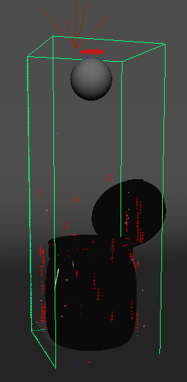
If the previous simulation's cache is visible inside the volume (as seen below in the green container), click the Clear Simulator Cache button from the PhoenixFD shelf, and then click Yes.

New Simulator volume in lavender, previous cache in green

Next, make sure the sphere is inside of the Simulator volume. If not, move the sphere into place.
The scene scale is very important to the simulation process, so take note of the units in your scene by choosing Windows > Settings/Preferences > Preferences, and in the Working Units section, check the Linear attribute.

The units do not have to be set to centimeters to get the Simulation to work. What's important is that the simulation object (in this case, the sphere) is set to the proper real-world scale so that the simulation is correct for that situation. This is how Phoenix is able to know if it's simulating water in a glass or a boat on ocean waves.
For this tutorial, make sure the sphere has a diameter of approximately 8 centimeters (or 3.15 inches) to make the simulation work for filling a simple glass or container.
Radius of 4 = diameter of 8
Select the volume, and double-check its dimensions from the Grid section's Total Cells entry.
The Units Scale parameter can be used to alter the overall scene scale to create smaller or larger simulations. Adjusting it forces the simulation to behaving as if the scene is at the defined scale. This value is automatically defined as needed by a preset, no matter the size of the scene.
Click the Liquid Source button in the Phoenix FD shelf and add the item to the viewport of your scene. Note: The object is a 2D non-renderable locator, so size and placement are only important for being able to select the Source when needed.
Select the sphere in the scene and Shift+Select the Source object. Then click the Add Selected Objects button in the Source Objects rollout in the Attribute Editor.

The Source node is where we control emitter properties, like the Discharge amount. The sphere is just the emitter object for the simulation, not the source of the fluid dynamics.
Select the Simulator volume again and open the Liquid rollout in the Attribute Editor and check the Enabled checkbox. Note: This is required because the Simulator in Maya is able to generate both Fire/Smoke sims and Liquid sims.

Start the simulation again to confirm that the sphere is emitting the liquid inside the volume. Note: This can also be done from the Start button at the top of the Attribute Editor.
The viewport preview of the simulation will appear mostly white; this is due to the speed of the particles. You can adjust that value by increasing the White Speed, which can be found under the Simulator's Preview rollout > Particle Preview sub-rollout. Set this value to around 730.
White Speed = 100 (default)
White Speed = 730
The simulation results do not look quite like the Preset version at this point; edges of the simulation are jagged. Expand the Dynamics rollout and take note of the default Steps Per Frame value.
Increase the Steps Per Frame setting to 12 to create a more realistic simulation. Re-simulate by clicking the Start button. The additional steps taken in each frame to calculate the simulation will increase the time it takes to simulate dramatically. Adjusting the SPF value should happen only when you're ready to switch from a quick preview to a more realistic final simulation.
With large scale liquid simulations, you can usually use less Steps Per Frame without sacrificing the look.
You may have noticed that the liquid flows right through the floor, and disappears. This means our Simulator is open and needs to be closed. In the Grid rollout, under Container Walls, set the X, Y, and Z axes to Jammed Both. Running the simulation again will now result in the liquid colliding with the bottom and side walls of the volume.

However, the sim is now running even slower, so we will adjust the resolution to address the loss of speed by increasing Cell Size. First, take note that we have about 4.7 million Total Cells to calculate in the sim. This is our simulation’s resolution. The larger the cell size value, the lower the simulation resolution, which will make it run faster.
Stop the sim, and increase the Cell Size value to 0.5 and Start the simulation again and you’ll see that it runs much faster.
Increasing Cell Size to 0.5 lowers the total resolution to about 3 million cells
Render a test frame in the V-Ray Frame Buffer, and note how the simulation looks nothing like water at this point.
Let's create a water material for the simulation. Open the Hypershade, and create a new V-Ray Material. Make sure your Material Viewer is set to V-Ray to preview the material as it's created.
Set the Diffuse Color to black, then set both the Reflection Color and Refraction Color values to white. Change the Refraction IOR to 1.33 to better represent water, and then toggle Affect Shadows on.

Now assign this new material to the simulator object in the scene. Click the Render button and you’ll see the simulation take on a more natural water look. Feel free to adjust the material and the lighting in the scene to achieve the desired liquid look.

Applying the Sim setup to a Real-world Example
Now let’s look at how to make the liquid collide with, and fill an actual object, rather than just the simulator’s box-like volume. Open the provided scene from the Tutorial Assets section above. It includes a scene with a jar in a studio lighting setup and backdrop. Switch your view to camera1 and render to see a solid gray jar and background.
Go back to your perspective camera, and select the sphere. In the Phoenix shelf, choose the Tap Water Quick Preset like we did at the beginning of this tutorial.
The simulator needs to be adjusted to properly work in our scene with the jar. Move the simulator to fit around the jar, and use the X, Y, and Z Size attributes to size the simulator shape it to have a little space between it and the jar.
Use the Size attributes of the simulator as opposed to simply scaling the simulator container with Maya's Scale tool, as that may adversely effect the simulation.
Start the simulation, and switch to the camera1 view.
Adjust the Glass material assigned to the jar so that the Diffuse Color to black, confirm that the Reflection Color is white, and then set Refraction Color values to white. The mesh will seemingly disappear in the viewport, but only because it is fully refractive now. Render a frame to see how the fluid is interacting with the jar.
Any geometry inside a simulation volume will automatically interact with the emitting fluid. There are techniques that we'll explore in later videos on exempting objects inside a Simulator from interacting with the simulation.
If you allow the simulation to run, it will eventually fill and overflow the jar. Stop the sim. Select the Liquid source object and take note of the Discharge parameter. This setting determines how much fluid is discharged by the emitter. Therefore, animating this value allows us to pour liquid into the jar, and then get it to stop. Set a Key on Discharge for 16.0 on frame 22. Then move to frame 23 and set another key with the value of 0.

Set key on Discharge = 16 at Frame 22

Set key on Discharge = 0.0 at Frame 23
Now Start the simulation and let it calculate to about Frame 50 so the animation can be seen. Then Stop the simulation and you can scrub the cached sim to evaluate its movement. Go to Frame 45 and make another render from camera1.
Notice that the fluid makes some drops that hit the in-sides of the simulator walls. This is fixed by making the liquid less spread out, as it falls into the jar. Also, take note of how the water is making contact with the top of the volume. We can fix that by moving the sphere down slightly to create a little more distance between it and the volume.
Next, select the simulator, and in the Grid section, under Container Walls, set the X, Y, and Z walls to be Open. This will keep any of those droplets from colliding with the imaginary walls.
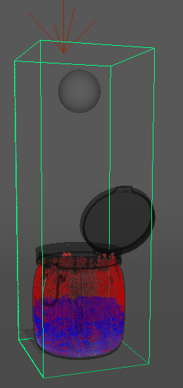
Go into the Liquid rollout, and set the Consumed Liquid attribute to 0.0. This value relates to the Wetting parameter, which creates these red particles we see wetting the inside of the jar creating a wet map. By setting Consumed Liquid to 0.0 we are preserving all the liquid, with none of it evaporating away.
Now let’s fix the spreading of the liquid as the emitter stops discharging. Select the Liquid source node, and change the Emit Mode to Volume Brush. What this means is that instead of emitting the liquid from the surface area of the sphere, it will now emit from the whole volume defined by sphere.

Confirm changing Emit Mode to Volume Brush
Select the emitter sphere, and in the Extra Phoenix FD Attributes for the shape node, turn off Solid. This means the sphere geometry itself will not interact with the liquid simulation.
Start the simulation, and you can see that the liquid is coming from the volume of the sphere now, as opposed to just from its outside surface. Stop the simulation when the jar is halfway filled up and scrub back and forth to see the pour nicely contained even after the Discharge value turns off at frame 23.
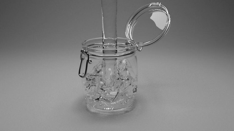
Render the result from the camera1 view, and you should have a nice jar of water like this!