This page provides a tutorial for using the Initial Liquid Fill setting and manually creating a liquid simulation inside a glass container.
Overview
This is an Entry Level tutorial which requires no previous knowledge of Phoenix. A basic understanding of Maya would be helpful but is not a prerequisite for being able to follow along.
The instructions on this page will guide you in creating an Initial Fill geometry and modifying a liquid simulation so that it can be contained inside of a wine glass or similar container. This includes adjusting the simulation so the liquid interacts and renders with the container appropriately.
This tutorial is created using Phoenix 4.41 Official Release and V-Ray 5, Update 1.2 Official Release for Maya 2018. You can download official Phoenix and V-Ray from https://download.chaos.com. If you notice a major difference between the results shown here and the behavior of your setup, please reach us using the Support Form.
The Download button below provides you with an archive containing the scene files.

Creating a Glass Geometry
To generate the wine glass, find a suitable reference image and trace it with the CV Curve Tool.
Make sure to trace both the inner and outer layer of the glass.

With the generated curve selected, go to Surfaces → Revolve.

Delete the History on the glass by going to Edit → Delete by Type → History. We will use Booleans to create the object used as a placeholder for the Initial Fill and the history may cause problems.
As Phoenix can't use the generated NURBS surface directly, we need to convert it to polygons.
Select the generated surface and go to Modify → Convert → NURBS to Polygons (options).
Set the Tessellation method to Control points.
It would be a good idea to save the curve and the NURBS surface that you created earlier in a group node which you can then hide or delete. This way you can easily go and readjust the glass model if you need to make any changes.

The resulting geometry is likely to be very low-res so consider subdividing it before using it for simulation.
Go to Mesh → Smooth (options) and set the Division Levels to 2.
You will be left with a Solid geometry.
Rename the wine glass to glass_geo_01.

There should not be any issues with the geometry but in general, to check for problems with any model you can use Mesh → Cleanup.
Faces with holes, Lamina (overlapping) faces and Nonmanifold geometry could cause trouble in a simulation.

Create the Initial Fill Geometry
Create a poly Cube and place it so the bottom face is below the bowl area of the glass.
The top face will be the top of the liquid.
Make sure the side faces extend beyond the walls of the wine glass.

Duplicate the glass mesh object and hide the original.
Select the cube, then Shift-Select the duplicate glass and go to Mesh → Booleans → Intersection.
Go to Face component mode, double-click the outer hull to select all of the faces in that part of the geometry, and delete them.

Go back to Object Mode.
With the inner hull selected, go to Mesh → Fill Hole.

Confirm that the face normals are facing outward. To view the object normals, select the object and choose Display → Polygons → Face Normals.
Reverse the normals, if necessary, by going to Mesh Display → Reverse.
Then, Delete the History again.
Rename the initial fill geometry to glass_initial_fill_01.

You may want to increase the Scale of the initial fill geometry, so that its outside border stays between the glass geometry walls. We are doing this, because the initial fill geometry and the glass geometry have to intersect in order to get better results with the Render Cutter.

Phoenix Initial Fill
Select the glass_initial_fill_01 geometry and in the Attribute Editor, go to its Shape node tab.
Under Attributes → Phoenix FD → Phoenix FD Node Properties.
Enable Initial Liquid Fill on the Extra Phoenix FD Attributes tab. This will fill the geometry with liquid at the very beginning of the simulation.


Phoenix Fluid Simulator
Create a Phoenix Fluid Simulator that encompasses the fill object.
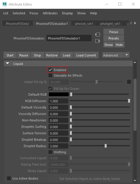
Go to the Liquid tab and select Enabled.
This is required, because the Simulator in Maya is able to generate both Fire/Smoke and Liquid simulations.
The Simulator → Grid parameters are tweaked as follows:
The Scene Scale is set to 25. When working with small scale water simulations, it's often hard to control the tiny jittering that tends to occur near collision objects without increasing the Steps Per Frame to prohibitively high values. Therefore, it's faster and easier to simply increase the Scene Scale a little. If your scene setup requires lower Scene Scale, you can compensate this by increasing the Steps Per Frame at the expense of increased simulation time.
The Cell Size is set to 0.15 cm. The lower the Cell Size is, the more detailed the simulation will be but the longer it will take to complete.
The X/Y/Z Size of the Simulator is set to 190/170/190.
Increasing the Grid Resolution of the Grid can sometimes alter the shape and behavior of the simulation. Remember that higher resolution does not necessarily mean more realistic simulations. It depends on the project. Sometimes the resolution is too high, and there are too many details, or the look is not what you want. You have to find a good balance.

In the Dynamics rollout, set the Steps Per Frame to 12. Higher Steps Per Frame values will result in a smoother liquid at the cost of increased simulation times.
In general, you should try to keep this as low as possible without compromising on the quality of your simulation.

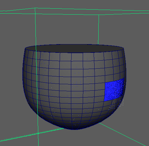
Start the simulation and let it run for 20 or so frames, and check the results.

This method can be very helpful when used with a tilted object.

Potential Issues
Here is a short list of common issues that might keep the process in this tutorial from turning out to be a success.
1. If the Initial Fill object is hidden, then nothing will be sourced into the simulation. Unhide the object or allow the Simulator to use Hidden Objects (disabled by default).

2. If the normals on the Initial Fill geometry are reversed, the fluid may appear outside the glass instead of on the inside. Try Normals → Reverse to flip the normals.

3. If there are holes in the Initial Fill geometry, try resolving by using Mesh → Fill Hole.
Liquid Rendering
Before starting to render, make sure to hide the Initial Fill geometry. One way to do this is to select the init_fill_geo in the Outliner and then press H.
Use the Render button to generate an image of the scene.
Notice the noise present on the surface of the liquid.

To resolve such issues, Phoenix provides you with the option to use the glass geometry as a Render Cutter. A Render Cutter is a piece of polygon geometry that will clip the rendering only to inside its volume.
Select the glass geometry and Shift+Select the Simulator.
Open the Rendering rollout and click on Set Selected Object as Render Cutter.
Nothing notable will happen in the Viewport but in the Rendering tab of the Simulator, the Cutter Geometry field will be populated by the name of the object that you chose as a cutter.
Geometry normals will affect how the Render Cutter behaves. When simulating fluids in hollow objects, make sure that the normals point inwards.

Press Render again.
Notice that the liquid only appears between the walls of the glass. As mentioned earlier, when the Cutter is enabled, the rendering will occur only inside the volume of the Cutter object geometry.

To resolve this, select the Invert Cutter option from the Rendering tab of the Simulator.

Press Render.
By default, the Render Mode is set to Mesh which may produce artifacts in the rendered image when used together with a Render Cutter.
Usually, when using a Render Cutter for a liquid pouring into a glass or liquids, contained into another refractive object, you may need to set the Render Mode to Isosurface.

Select the Simulator and go to the Rendering rollout.
Set the Render Mode to Isosurface. This will create a procedural isosurface without polygons at render time using the Isosurface Level option. Note that this method requires V-Ray.
Compared to the Mesh Mode, the Isosurface is always smooth but it will take longer to render. In case you use Mesh Mode and your mesh is too jagged and edgy, and smoothing it out is too slow or impossible, this means you should switch to Isosurface Mode instead.

And here is the final render with applied wine material, taken from the V-Ray Material Library.
