This page provides a tutorial for cascading two or more liquid simulations.
Overview
This is an Intermediate Level tutorial. Even though no previous knowledge of Phoenix is required to follow along, re-purposing the setup shown here to another shot may require a deeper understanding of the host platform's tools, and some modifications of the simulation settings.
The instructions on this page will guide you in modifying a liquid simulation so that it cascades into another simulation. This is used to connect multiple simulations together for situations like a waterfall connecting to a river. It can also be used to divide up simulations that would otherwise require a very large simulation grid.

Steps
To follow along this tutorial, you can either download the provided project files, go through the Creating a Simple Liquid Simulation tutorial or modify your own custom liquid simulation setup.
In this example, the tutorial starts with the Project Files download.

Create a second Phoenix Liquid Simulator and rename the nodes as follows:
1. Rename the simulator node to phx_simulator_02.
2. Rename the generated sets to phx_sim_set_02 , phx_lgt_set_02 and phx_preview_set_02. For more information on the purpose of those sets, please check the Creating a Simple Liquid Simulation tutorial.
Select phx_simulator_02 and in the Attribute Editor, use the mode dropdown menu to select Liquid. This preset sets up the necessary parameters for a FLIP simulation.
Notice the overlap between the bounding boxes of the simulators. This is required for the transfer of particles between the two grids.

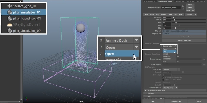
In the Grid tab of phx_simulator_01, set the Container Walls Y to Open.
When creating a Cascade setup, it is important to keep in mind the Container Walls settings of the participating Simulators.
The liquid should be able to exit the first simulator in order to enter the second one.
Thus, both the bottom of phx_simulator_01 and the top of phx_simulator_02 need to be Open.
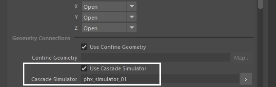
To create the Cascade connection between the simulators, first select the destination (phx_simulator_02) then the source (phx_simulator_01) and go to Phoenix FD Menu → Set Simulator Cascade Connection.

You should now have a link between the two grids.
Note that in the Attribute Editor -> Grid tab of phx_simulator_02, the source simulator is listed under the Cascade Simulator field.
The last step is to make sure that Velocity channel export is enabled from the Output tab for the source simulator.
Select phx_simulator_01, go to the Attribute Editor → Output and enable Velocity.
If the Velocity channel export is disabled, Phoenix will print the following warning in the Script Editor:
// Warning: Phoenix FD: Cascade connection will not work properly due to missing channels in the Source simulator!
Please export them from the Source simulator's Output panel, simulate it again,
and then run this simulator again. The missing channels are: Grid Velocity //

Select phx_simulator_01, press Start and wait for the simulation to finish.
The workflow is as follows:
First, the source grid is simulated and the contents are cached to disk.
Then, once the first simulation is complete, you start the second simulation.
The second simulator uses the cached files to determine where to add the liquid and how it should move once generated. This is why the Velocity channel from the first (source) simulator is required.

When the first simulation is complete, select phx_simulator_02 and press Start.
The liquid that exits from the bottom of the source simulator appears at the top of the destination one.
You may repeat those steps to link a 3-rd simulator to the 2-nd one, and so on.
If you notice a mismatch between the density of the liquid particles in the 2 simulators, make sure that the Preview tab → Detail Reduction parameter has the same value for both grids.
