This page provides information on the V-Ray EnvironmentFog node.
Page Contents
Overview
V-Ray EnvironmentFog is an atmospheric effect that allows the simulation of participating media like fog, atmospheric dust, and so forth. Volumetric properties can be determined by 3D texture maps. The atmospheric effect can also be confined with geometry objects.
V-Ray EnvironmentFog can use either of two algorithms to calculate volumetric lighting. The first algorithm is a simple exponential sampling scheme, which is used when there are no texture maps specified. In this mode, V-Ray takes a number of random points inside the volume and calculates the volumetric lighting at those points. The second algorithm is a raymarching scheme, which is used when any of the volume properties are mapped with a texture. In that case, V-Ray traverses the fog volume in small steps, calculates the volume properties at each step, and computes the volume lighting accordingly.
UI Paths:
||mat Network|| > Effect > Fog
||shop Network|| > V-Ray Material node > Effect > Fog
Parameters
Enabled – Enables or disables the V-Ray Fog.
Fog Color – Defines the color of the fog when it is illuminated by light sources. For more information, see the Color example below.
Fog Color (map) – Specifies a map to define the fog color when it is illuminated by light sources. For more information, see the Color example below.
Fog Multiplier – The strength of the fog effect. Smaller values reduce the effect of the fog, making the material more transparent. Larger values increase the fog effect, making the material more opaque.
Emission Color – Controls the fog emission (self-illumination). You can use this parameter to substitute the ambient illumination inside the fog, instead of using GI. For more information, see the Emission example below.
Emission Color (map) –Specifies a map to control the fog emission (self-illumination). You can use this parameter to substitute the ambient illumination inside the fog, instead of using GI. For more information, see the Emission example below.
Emission Multiplier – A multiplier for the fog emission.
Fog Distance – Controls the fog density by specifying the distance between fog particles. Larger values make the fog more transparent, while smaller values make it more dense. For more information, see the Fog Distance example below.
Fog Density – A multiplier for the Fog Distance parameter.
Fog Density (map) – A multiplier for the Fog distance parameter that allows a texture to be used for the density of the fog.
Opacity Mode – When enabled treats the Fog Density as opacity instead.
Use Height – When enabled, V-Ray will take height into account when calculating the fog. If the fog is not contained within a volume, it is assumed to start from a certain Y-level height and continue downward indefinitely.
Height – Determines the starting point for the fog along the Y-axis. For more information, see the Fog Height example below.
Subdivs – Determines the number of points inside the fog at which volumetric lighting is evaluated. Smaller values for this parameter render faster, but may produce noise in the image. Higher values render longer, but with less noise. It is only used when there are no texture maps specified, in which case the volume properties are the same everywhere. For more information, see the Sampling Parameters example below.
Y is Up – When enabled, the Y axis is treated as the up axis. When disabled, the Z axis is the up axis instead.
Solid Mode – When enabled, disables randomization when sampling. Instead, one sample will be taken at 0.5 density, and the fog will be rendered as a solid object.
Solid Threshold – When using Solid Mode, specifies the threshold below which the fog is considered solid..
Jitter – When rendering a volumetric object, some artifacts may occur due to the regular raymarching step. Enabling this option can prevent this by adding a small random offset to the step.
Shadow Opacity – Specifies the volume opacity scale for shadow rays.
Scale – Stretches the aspect for the 3 axes. This is useful when the fog container must grow/shrink while preserving its original density.
Fade Out Mode – Specifies between two different modes fading out the fog:
Multiply – Multiplies by the fog density.
Subtract – Subtracts the density from the falloff.
Fade Out Radius – Specifies a radius for the fade out of the fog.
Per Object Fade Out Radius – When enabled, the fade out effect we be applied to each fog volume independently.
Scatter GI – When enabled, the fog will also scatter global illumination. Note that this can be quite slow. In many cases, global illumination within the fog can be substituted with a simple emission term. When this option is enabled, the currently selected global illumination algorithm in the V-Ray settings will be used to accelerate GI inside the volume (e.g. the irradiance map, light cache, or brute-force). For more information, see the Scatter GI and Scatter bounces example and the Importance of GI example below.
Scatter bounces – When Scatter GI is enabled, this controls the number of GI bounces that will be calculated inside the fog.
Simplify Textures for GI – When enabled, V-Ray will use a simplified method for calculating the GI when rendering parts of the fog that are textured or are being faded out.
Step Size – Determines the size of one step through the volume. Smaller steps produce more accurate results but are slower to render. In general, dense volumes require smaller step sizes than more transparent volumes. In practice, step sizes that are two to three times smaller than the Fog Distance parameter work well.
Max Steps – Specifies the maximum number of steps through the volume.
Texture Samples – Determines the number of texture samples for each step through the volume. Higher values sample textures more accurately than the volumetric lighting. This setting is useful in cases where the textures vary much more than the lighting itself (e.g. for detailed fractal textures). For more information, see the Texture Samples example below.
Cutoff Threshold – Controls when the raymarcher will stop traversing the volume. If the accumulated volume transparency falls below this threshold, the volume will be considered opaque and tracing will be aborted. Higher values make the rendering faster but may introduce artifacts.
Light Mode – Allows you to specify which lights will be considered when rendering the environment fog. It is used when you have certain lights affecting just specific objects in the scene while another group of lights is affecting the environment fog. For more information, see the Volumetric Caustics example below.
No lights – The lights in the scene will not affect the environment fog.
Per-Gizmo – The lights attached to the environment fog set will be ignored. Only the lights affecting the gizmos where the fog resides will be used.
Override – Only the lights affecting the environment fog set will be considered.
Intersect – Only lights that are affecting both the shape and the environment fog set will be considered.
Add – Both lights that are affecting the shape and the environment fog set will be considered.
Use Shade Instance – When enabled, the shade instance will be used when sampling textures.
Affect Background – Enables or disables the tracing of background rays through the volumetric. When disabled, the background will not be obscured by the fog.
Affect Reflections – Enables or disables the tracing of reflection rays through the volumetric.
Affect Refractions – Enables or disables the tracing of refraction rays through the volumetric.
Affect Shadows – Enables or disables the tracing of shadow rays through the volumetric.
Affect GI – Enables or disables the tracing of GI rays through the volumetric.
Affect Camera – Enables or disables the tracing of Camera rays through the volumetric.
Deep Output – Enables depth data output using deep images for use in deep compositing applications.
Ior – Index of Refraction for the volume, which describes the way light bends when crossing the material surface. A value of 1.0 means the light will not change direction.
Use Shade Data – When enabled, the shade data will be used when sampling textures.
Note: The Light Mode will be ignored if this is true and the shader is not global.
Example: Color
This example demonstrates the effect of the fog Color. Note how color only changes the way the volume reacts to light, and not the volume transparency. In this example, the fog density is mapped with a checker texture. A polygon box has been used to confine the fog volume with the VRayEnvironmentFog set as the Volume material in the shading group of the box. The opacity of the boxes Surface material has been set to be 100 transparent by changing its Opacity Map to a black color. This means the Surface material has no contribution to the shading of the box, only the VRayEnvironmentFog material.
In the following examples, the fog Color has been mapped with a texture. World XYZ mapping type was used for the textures.
A Gradient Ramp texture with Solid interpolation
A Noise texture
Example: Emission
This example demonstrates the effect of the Emission parameter. The Fog color is gray so as to better show the effect of the emission. Note that since we also have GI enabled, the fog emission causes the volume to illuminate both itself and other objects around it. The fog density is mapped with a Checker texture. A polygon box has been used to confine the fog volume with the VRayEnvironmentFog set as the Volume material in the shading group of the box. The opacity of the boxes Surface material has been set to be 100 transparent by changing its Opacity Map to a black color. This means the Surface material has no contribution to the shading of the box, only the VRayEnvironmentFog material.
Emission is black (no emission)
Color is gray
Emission is dark blue
Color is gray
Emission is dark blue, Color is black
(Only the fog emission affects the image.)
In the following examples, the Emission has been mapped with a texture. The Color is gray to better show the light scattering inside the volume, produced by the global illumination. The scene for the last image is available here.
Emission is mapped with a Gradient Ramp texture
Emission is mapped with a red Noise texture
Example: Fog distance
This example demonstrates the effect of the Fog distance parameter. Note how larger values make the fog more transparent. A polygon box has been used to confine the fog volume with the VRayEnvironmentFog set as the Volume material in the shading group of the box. The opacity of the boxes Surface material has been set to be 100 transparent by changing its Opacity Map to a black color. This means the Surface materia has no contribution to the shading of the box, only the VRayEnvironmentFog material.
Fog distance is 4.0
Fog distance is 16.0
Fog distance is 64.0
In the following examples, the fog density has been mapped with a texture. World XYZ mapping type was used for the textures.
No texture
Checker texture
Regular Noise texture
Inverted turbulence Noise texture
Example: Fog height
When there are no geometry nodes connected to VRayEnvironmentFog, the volume occupies space downward from a certain height along the scene Z-axis, determined by the Fog height parameter. The following examples demonstrate this. Note that as the Fog height is increased, the scene becomes darker - this is because the sun is blocked by a larger amount of fog. This can be corrected by increasing the Fog distance parameter, and thus making the fog more transparent. Note also the sudden decrease of brightness when the camera is included inside the fog volume.
Fog distance = 40
Fog height = 20
Fog distance = 40
Fog height = 40
Fog distance = 40
Fog height = 100
Fog distance = 40
Fog height = 200
Fog distance = 200
Fog height = 20
Fog distance = 200
Fog height = 40
Fog distance = 200
Fog height = 100
Fog distance = 200
Fog height = 200
Example: Sampling parameters (without textures)
When no textures are used, VRayEnvironmentFog uses a simple sampling algorithm where samples are distributed according to the volume density. The only quality parameter for this sampler is the Subdivs parameter.
Subdivs is 1
Subdivs is 8
Subdivs is 16
Example: Scatter GI and Scatter bounces
This example demonstrates the effect of the Scatter GI and Scatter bounces parameters. Note how multiple scattering of light inside the volume greatly increases the realism of the image.
GI is off in the V-Ray settings.
The fog volume only shows direct lighting.
GI is on, Scatter GI is off.
The fog does not scatter GI and so looks identical to the left image (it is lit with direct light only).
GI is on, Scatter GI is on, Scatter bounces is 1.
Notice how the fog volume is affected by the skylight. The irradiance map was used for a primary GI engine.
GI is on, Scatter GI is on, Scatter bounces is 2
Irradiance map + brute force GI for secondary bounces
GI is on, Scatter GI is on,Scatter bounces is 4
Irradiance map + brute force GI
GI is on, Scatter GI is on, Scatter bounces is 8
Irradiance map + brute force GI
GI is on, Scatter GI is on, Scatter bounces is 100
Irradiance map + Light cache for secondary bounces
Example: Importance of GI
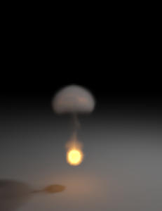
GI scattering is especially important when creating cloud-like volumes. For example, compare the following two images, done with and without GI scattering.
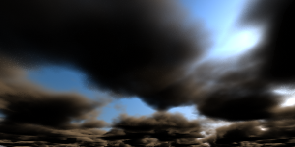
Global illumination is off
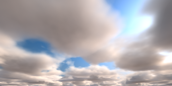 Global illumination is on (irradiance map + light cache) with Scatter GI on and Scatter bounces set to 100
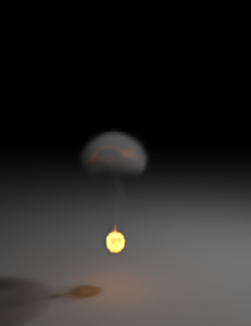
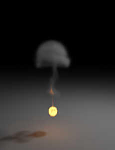
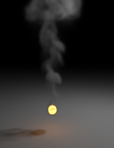
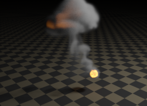
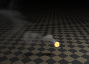
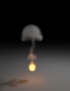
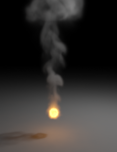
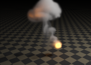
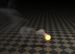
The following example shows GI scattering inside a smoke volume. The volumetric textures (density and emission) for this example are provided from a fluid dynamics simulation in the form of 3D textures. Irradiance map and the light cache are used for both sequences. Note how GI scattering causes the smoke to be naturally illuminated by the fire in the second row of images.
Example: Texture samples with ray marching
The following example demonstrates the effect of the Texture samples parameter. This parameter allows for more accurate sampling of textures with rapid changes, without the need to increase the Step size parameter, and thus saving render time.

Texture samples is 1, Step size is 4.0
Note the noise.

Texture samples is 4, Step size is 4.0
Much better result, with only minor increase in render time.
 Texture samples is 1, Step size is 1.0
In practice, the texture is sampled with the same rate as with the image on the left, but render time is greatly increased, since lighting is also sampled at a greater rate.
Example: Volumetric Caustics
This example demonstrates volumetric caustics and colored shadows with different settings.
Caustics are off, Affect shadows for the sphere material is off
Caustics are off, Affect shadows for the sphere material is on
Caustics are on
Caustics are on, and the fog density is mapped with a Smoke texture
The quality of the volumetric caustics depends on the sampling of the volume fog, on the V-Ray caustics settings, and the caustics settings for the light. In the first two images below, all parameters are same with the exception of the caustics subdivs for the light. Note how the more photons are shot, the more defined the caustics are. In this example, we also have the caustics Max. density parameter set to 0.3 in order to limit the photon density in the caustics map. This saves memory and makes the rendering faster, although it will limit the spatial resolution of the caustics (in our case, to 0.3 scene units).
The light has 100 Caustics subdivs (10,000 caustics photons are shot).
The light has 500 Caustics subdivs (250,000 caustics photons are shot).
Note the broken caustics beam - this is not because there are not enough
caustics photons, but because we don't have enough samples for the fog itself.
The light has 500 Caustics subdivs again, but the fog Subdivs parameter is set to 32.
Note the improved sampling of the caustics beam.