![]()
Page History
...
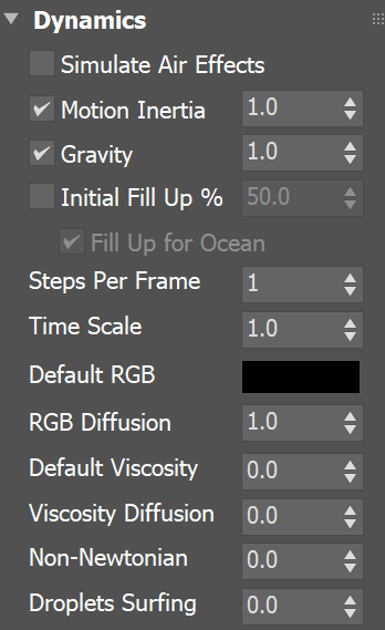
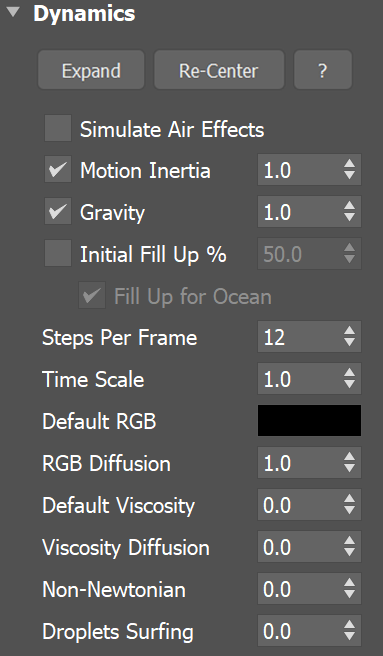
| UI Text Box | ||
|---|---|---|
| ||
UI Path: ||Select Liquid Simulator | LiquidSim object|| > Modify panel > Dynamics rollout |
Parameters
...
| Section | ||||||||||||||||||||||||||||||||||||||||||||||||||||||||||||||||||||||||||||||||||||||||||||||||
|---|---|---|---|---|---|---|---|---|---|---|---|---|---|---|---|---|---|---|---|---|---|---|---|---|---|---|---|---|---|---|---|---|---|---|---|---|---|---|---|---|---|---|---|---|---|---|---|---|---|---|---|---|---|---|---|---|---|---|---|---|---|---|---|---|---|---|---|---|---|---|---|---|---|---|---|---|---|---|---|---|---|---|---|---|---|---|---|---|---|---|---|---|---|---|---|---|
|
| Anchor | ||||
|---|---|---|---|---|
|
...
Example: Motion Inertia
...
| UI Text Box | ||
|---|---|---|
| ||
The following video provides examples of moving containers with Motion Inertia enabled to show the differences between values of 0, 0.5, and 1.0. |
| Align | ||
|---|---|---|
| ||
|
Software used: Phoenix
...
4.30.00 Official Release
| UI Button | ||||||||
|---|---|---|---|---|---|---|---|---|
|
...
Anchor FillupForOceanClearInside FillupForOceanClearInside
...
| UI Text Box | ||
|---|---|---|
| ||
This example shows the Liquid voxels, with a submerged Solid ellipsoid. There are never FLIP particles inside it, but disabling Clear Inside will fill it with Liquid voxels so the liquid mesh can intersect it. |
| Section | |||||||||||||||||||||||||||||||||
|---|---|---|---|---|---|---|---|---|---|---|---|---|---|---|---|---|---|---|---|---|---|---|---|---|---|---|---|---|---|---|---|---|---|
|
| Anchoranchor | ||||
|---|---|---|---|---|
|
...
Example: Steps Per Frame
...
| UI Text Box | ||
|---|---|---|
| ||
The following video provides examples to show the differences of Steps Per Frame values at 1, 5, and 15. |
| Align | ||
|---|---|---|
| ||
|
Software used: Phoenix
...
4.30.01 Nightly (02 Oct 2020)
| UI Button | ||||||||
|---|---|---|---|---|---|---|---|---|
|
...
...
| Section | ||||||||
|---|---|---|---|---|---|---|---|---|
| UI Text Box | ||||||||
| ||||||||
The following video provides examples to show the differences of Time Scale with values of 0.3, 1.0, and 2.0. |
| Align | ||
|---|---|---|
| ||
|
Software used: Phoenix FD 4.30.01 Nightly (02 Oct 2020)
| UI Button | ||||||||
|---|---|---|---|---|---|---|---|---|
|
...
...
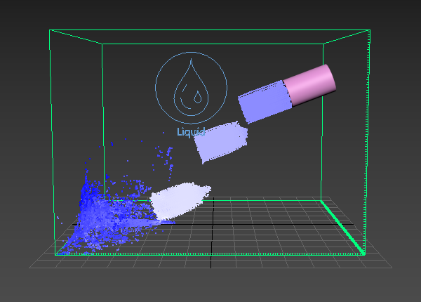
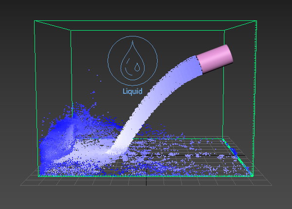
Here is the difference between Steps Per Frame values of 1 and 10 when a Source emits liquid with high velocity. |
| Section | ||||||||||||||||||||||||||||||||
|---|---|---|---|---|---|---|---|---|---|---|---|---|---|---|---|---|---|---|---|---|---|---|---|---|---|---|---|---|---|---|---|---|
|
| Anchor | ||||
|---|---|---|---|---|
|
Example: Time Scale
...
| UI Text Box | ||
|---|---|---|
| ||
The following video provides examples to show the differences of RGB DiffusionTime Scale with values of 0. 03, 1.0 .5, and 12.0. |
| Align | ||
|---|---|---|
| ||
|
Software used: Phoenix
...
4.30.01 Nightly (02 Oct 2020)
| UI Button | ||||||||
|---|---|---|---|---|---|---|---|---|
|
...
|
| Anchor | ||||
|---|---|---|---|---|
|
...
Example:
...
RGB Diffusion
...
| UI Text Box | ||
|---|---|---|
| ||
The following video provides examples to show the differences of Default ViscosityRGB Diffusion with values of 0.0, 0.5, and 1.0. |
| Align | ||
|---|---|---|
| ||
|
Software used: Phoenix
...
4.30.01 Nightly (02 Oct 2020)
| UI Button | ||||||||
|---|---|---|---|---|---|---|---|---|
|
...
|
| Anchor | |||
|---|---|---|---|
|
|
...
Example:
...
Default Viscosity
...
| UI Text Box | ||
|---|---|---|
| ||
The following video provides examples to show the differences of Non-NewtonianDefault Viscosity with values of 0.0, 0. 15, and 1.0. |
| Align | ||
|---|---|---|
| ||
|
Software used: Phoenix
...
4.30.01 Nightly (02 Oct 2020)
| UI Button | ||||||||
|---|---|---|---|---|---|---|---|---|
|
...
...
...
|
| Anchor | ||||
|---|---|---|---|---|
|
Example: Non-Newtonian
...
| UI Text Box | ||
|---|---|---|
| ||
The following video provides examples to show the differences of Droplets SurfingNon-Newtonian with values of 0 .0, 0. 51, and 1.0. |
| Align | ||
|---|---|---|
| ||
|
Software used: Phoenix
...
4.30.
...
01 Nightly (02 Oct 2020)
| UI Button | ||||||||
|---|---|---|---|---|---|---|---|---|
|
...
...
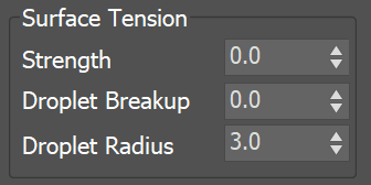
Surface Tension
| Section | ||||||||||||||||||||
|---|---|---|---|---|---|---|---|---|---|---|---|---|---|---|---|---|---|---|---|---|
|
...
...
Example: Surface Tension
...
| type | info |
|---|
...
|
| Anchor | ||||
|---|---|---|---|---|
|
Example: Droplets Surfing
...
| UI Text Box | ||
|---|---|---|
| ||
The following video provides examples to show the differences of Droplets Surfing with values of 0.0, 0.5, and 1.0. |
| Align | ||
|---|---|---|
| ||
|
Software used: Phoenix 4.30.00 Official Release
| UI Button | ||||||||
|---|---|---|---|---|---|---|---|---|
|
| Anchor | ||||
|---|---|---|---|---|
|
Surface Tension
...
| Section | ||||||||||||||||||||
|---|---|---|---|---|---|---|---|---|---|---|---|---|---|---|---|---|---|---|---|---|
|
| Anchor | ||||
|---|---|---|---|---|
|
Example: Surface Tension
| Align | ||
|---|---|---|
| ||
|
Software used: Phoenix FD 4.30.01 Nightly (02 Oct 2020)
| UI Button | ||||||||
|---|---|---|---|---|---|---|---|---|
|
...
...
...
| UI Text Box | ||
|---|---|---|
| ||
The following video provides examples to show the differences of Droplet Breakup withof Surface Tension with values of 0.0, 0. 507, 10. 028 and Surface TensionDroplet Formation with value of 0. 10. |
| Align | ||
|---|---|---|
| ||
|
Software used: Phoenix
...
4.30.01 Nightly (02 Oct 2020)
| UI Button | ||||||||
|---|---|---|---|---|---|---|---|---|
|
...
|
...
|
| Anchor | |||
|---|---|---|---|
|
...
|
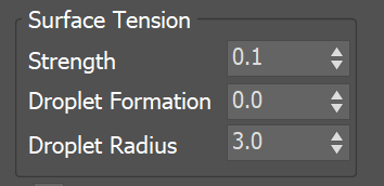
Example: Droplet Formation
...
| UI Text Box | ||
|---|---|---|
| ||
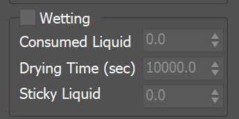
The simulation of wetting can be used in rendering for blending wet and dry materials, depending on which parts of a geometry have been in contact with the simulated liquid. Wetting can also change the behavior of a simulated viscous liquid and make it stick to geometries. The wetting simulation produces a particle system called WetMap. Wetmap particles are created at the point of contact between the liquid and the scene geometry, and can be rendered using a Particle Texture map. When used with a Blend Material, the Particle Texture acts as a mask to blend between two materials, for example, a wet material and a dry surface material. This way, geometry covered by WetMap particles can appear wet, and the rest of the geometry can appear dry. |
| Section | ||||||||||||||||||||
|---|---|---|---|---|---|---|---|---|---|---|---|---|---|---|---|---|---|---|---|---|
|
...
...
Example: Consumed Liquid
| UI Text Box | ||
|---|---|---|
| ||
The following video provides examples to show the differences of Consumed Liquid values of 0, 0.1, and 0.3. |
| Align | ||
|---|---|---|
| ||
|
Software used: Phoenix FD 4.30.01 Nightly (02 Oct 2020)
| UI Button | ||||||||
|---|---|---|---|---|---|---|---|---|
|
...
...
following video provides examples to show the differences of Droplet Formation with values of 0.0, 0.5, 1.0 and Surface Tension with value of 0.1. |
| Align | ||
|---|---|---|
| ||
|
Software used: Phoenix 4.30.01 Nightly (02 Oct 2020)
| UI Button | ||||||||
|---|---|---|---|---|---|---|---|---|
|
| Anchor | ||||
|---|---|---|---|---|
|
Wetting
...
| UI Text Box | ||
|---|---|---|
| ||
The simulation of wetting can be used in rendering for blending wet and dry materials, depending on which parts of a geometry have been in contact with the simulated liquid. Wetting can also change the behavior of a simulated viscous liquid and make it stick to geometries. The wetting simulation produces a particle system called WetMap. Wetmap particles are created at the point of contact between the liquid and the scene geometry, and can be rendered using a Particle Texture map. When used with a Blend Material, the Particle Texture acts as a mask to blend between two materials, for example, a wet material and a dry surface material. This way, geometry covered by WetMap particles can appear wet, and the rest of the geometry can appear dry. |
| Section | ||||||||||||||||||||
|---|---|---|---|---|---|---|---|---|---|---|---|---|---|---|---|---|---|---|---|---|
|
| Anchor | ||||
|---|---|---|---|---|
|
Example: Consumed Liquid
...
| UI Text Box | ||
|---|---|---|
| ||
The following video provides examples to show the differences of Stickyof Consumed Liquid valuesvalues of 0, 0. 51, and 1, when the Viscosity is set to 00.3. |
| Align | ||
|---|---|---|
| ||
|
Software used: Phoenix
...
4.
...
30.
...
01 Nightly (
...
02 Oct 2020)
| UI Button | ||||||||
|---|---|---|---|---|---|---|---|---|
|
...
|
| Anchor | ||||
|---|---|---|---|---|
|
...
Example: Sticky Liquid
...
without Viscosity
...
| UI Text Box | ||
|---|---|---|
| ||
The following video provides examples to show the differences of Viscosity values of 0.1,of Sticky Liquid values of 0, 0.5, and 1.0 and Sticky Liquid with value of1.and 1, when the Viscosity is set to 0. |
| Align | ||
|---|---|---|
| ||
|
Software used: Phoenix
...
4.41.02 Nightly (24 Jun 2021)
| UI Button | ||||||||
|---|---|---|---|---|---|---|---|---|
|
...
...
|
Example: Sticky Liquid
...
and Viscosity
...
| UI Text Box | ||
|---|---|---|
| ||
The following video provides examples to show the differences of Surface ForceViscosity values of 50, 500, and 1000,0.1, 0.5, and 1.0 and Sticky Liquid with value of 0.5 and Viscosity with value of1.0. 3. |
| Align | ||
|---|---|---|
| ||
|
Software used: Phoenix
...
4.
...
41.
...
02 Nightly (
...
24 Jun 2021)
| UI Button | ||||||||
|---|---|---|---|---|---|---|---|---|
|
...
|
Example: Sticky Liquid with different amount of fluid
...
| UI Text Box | ||
|---|---|---|
| ||
Note that interaction between Active Bodies and the Phoenix Fire/Smoke Simulator is not supported. |
Chaos Phoenix can make a ship, or ice cubes, or other geometry float in water using the Active Bodies feature, which introduces Rigid Body Dynamics for specified Active Body objects. Phoenix can even simulate waves that can carry Active Body objects around, or wash them away.
To use Active Bodies, you’ll need to create an Active Body Solver component, and specify the scene geometry which will partake in the Active Bodies simulation. Then, in the simulator’s Dynamics rollout, enable the Active Bodies parameter, and specify the Active Body Solver node.
You can then set the density and other Active Body properties in the Chaos Phoenix Per-Node Properties menu for each Active Body object.
| UI Text Box | ||
|---|---|---|
| ||
The Active Bodies simulation currently supports interaction between scene geometry and the Phoenix Liquid Simulator. When an object is selected as an Active Body, the simulation both influences and is influenced by the Active Body's movement. |
| UI Text Box | ||
|---|---|---|
| ||
For more information on Active Bodies, please check out the Active Body Solver and the Active Bodies Setup Guide. |
| Section | |||||||||||||||
|---|---|---|---|---|---|---|---|---|---|---|---|---|---|---|---|
|

...
| |
The following video provides examples to show the differences of Surface Force values of 50, 500, and 1000, Sticky Liquid with value of 0.5 and Viscosity with value of 0.3. |
| Align | ||
|---|---|---|
| ||
|
Software used: Phoenix 4.30.01 Nightly (02 Oct 2020)
| UI Button | ||||||||
|---|---|---|---|---|---|---|---|---|
|
Active Bodies
...
| UI Text Box | |||
|---|---|---|---|
| |||
Note that interaction between Active Bodies and the Phoenix Fire/Smoke Simulator is not supported. |
Chaos Phoenix can make a ship, or ice cubes, or other geometry float in water using the Active Bodies feature, which introduces Rigid Body Dynamics for specified Active Body objects. Phoenix can even simulate waves that can carry Active Body objects around, or wash them away.
To use Active Bodies, you’ll need to create an Active Body Solver component, and specify the scene geometry which will partake in the Active Bodies simulation. Then, in the simulator’s Dynamics rollout, enable the Active Bodies parameter, and specify the Active Body Solver node.
You can then set the density and other Active Body properties in the Phoenix Per-Node Properties menu for each Active Body object.
| UI Text Box | ||
|---|---|---|
| ||
The Active Bodies simulation currently supports interaction between scene geometry and the Phoenix Liquid Simulator. When an object is selected as an Active Body, the simulation both influences and is influenced by the Active Body's movement. |
| UI Text Box | ||
|---|---|---|
| ||
For more information on Active Bodies, please check out the Active Body Solver and the Active Bodies Setup Guide. |
| Section | |||||||||||||||
|---|---|---|---|---|---|---|---|---|---|---|---|---|---|---|---|
|
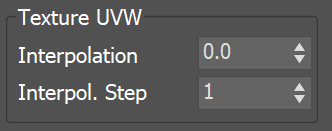
Texture UVW
...
| UI Text Box | ||
|---|---|---|
| ||
The main purpose of the Texture UVW feature is to provide dynamic UVW coordinates for texture mapping that follow the simulation. If such simulated texture coordinates are not present for mapping, textures assigned to your simulation will appear static, with the simulated content moving through the image. This undesired behavior is often referred to as 'texture swimming'. UVW coordinates are generated by simulating an additional Texture UVW Grid Channel which has to be enabled under the Output rollout for the settings below to have any effect. The custom UVW texture coordinates can be used for advanced render-time effects, such as recoloring of mixing fluids, modifying the opacity or fire intensity with a naturally moving texture, or natural movement of displacement over fire/smoke and liquid surfaces. For more information, please check the Texture mapping, moving textures with fire/smoke/liquid, and TexUVW page The main purpose of the Texture UVW feature is to provide dynamic UVW coordinates for texture mapping that follow the simulation. If such simulated texture coordinates are not present for mapping, textures assigned to your simulation will appear static, with the simulated content moving through the image. This undesired behavior is often referred to as 'texture swimming'. UVW coordinates are generated by simulating an additional Texture UVW Grid Channel which has to be enabled under the Output rollout for the settings below to have any effect. The custom UVW texture coordinates can be used for advanced render-time effects, such as recoloring of mixing fluids, modifying the opacity or fire intensity with a naturally moving texture, or natural movement of displacement over fire/smoke and liquid surfaces. Some examples uses are:
The Texture UVW channel values represent the UVW coordinates of each Cell in the Simulator, with a range of [ 0 - 1 ]. The channel is initialized when a simulation is started in one of two ways: . |
| Section | |||||||||||||||||
|---|---|---|---|---|---|---|---|---|---|---|---|---|---|---|---|---|---|
|
...
| Anchor | ||||
|---|---|---|---|---|
|
...
Example: Interpolation
...
| UI Text Box | ||
|---|---|---|
| ||
The following video provides examples to show the differences of Interpolation values of 0, 0.1, and 1, and an Interpolation Step with value of 1.0. |
| Align | ||
|---|---|---|
| ||
|
Software used: Phoenix
...
4.30.01 Nightly (02 Oct 2020)
| UI Button | ||||||||
|---|---|---|---|---|---|---|---|---|
|
| Anchor | ||||
|---|---|---|---|---|
|
...
Example: Interpolation Step
...
| UI Text Box | ||
|---|---|---|
| ||
The following video provides examples to show the differences of Interpolation Step values of 1, 3, and 6, and an Interpolation with value of 1.0. |
| Align | ||
|---|---|---|
| ||
|
Software used: Phoenix
...
4.30.01 Nightly (02 Oct 2020)
| UI Button | ||||||||
|---|---|---|---|---|---|---|---|---|
|
...