![]()
Page History
...
| UI Text Box | ||
|---|---|---|
| ||
UI Path: ||Select PhoenixFDSim|| > Attribute Editor > Grid rollout |
Parameters
...
| Section | |||||||||||||||||||
|---|---|---|---|---|---|---|---|---|---|---|---|---|---|---|---|---|---|---|---|
| |||||||||||||||||||
|
| Anchor | ||||
|---|---|---|---|---|
|
Example: Scene Scale
...
...
...
| UI Text Box | ||
|---|---|---|
| ||
The following video provides examples to show the differences of Scene Scale with values of 0.1, 5.0 and 15.0. |
| Align | ||
|---|---|---|
| ||
|
| Anchor | ||||
|---|---|---|---|---|
|
...
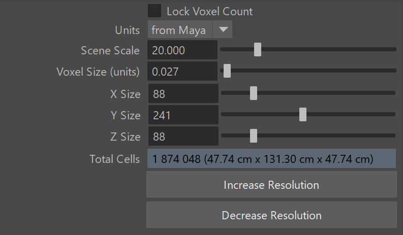
Example: Grid Resolution
...
...
| UI Text Box | ||
|---|---|---|
| ||
The following video provides examples to show the differences when the Total cells from the Grid's Resolution is at 570,000, 4,000,000and 16,000,000. |
| Align | ||
|---|---|---|
| ||
|
...
| Anchor | ||||
|---|---|---|---|---|
|
...
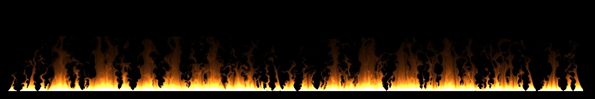
Example: Setting up a 2D Simulation
...
| UI Text Box | ||
|---|---|---|
| ||
A 2D Simulation can be performed by adjusting the Grid dimensions such that either X Size, Y Size, or Z Size is set to 1. The main application of this feature is to create very wide fires that would otherwise be time-consuming with a 3D simulation, like the image below. To keep features like the embedded gravity and pressure decay, it is recommended to leave the Y direction active and set the X or Z size to 1. |
...
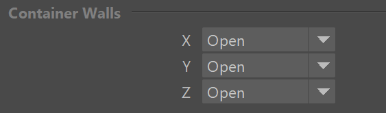
Container Walls
...
| Section |
|---|
...
|
...
|
...
|
...
|
...
|
...
|
...
|
...
|
...
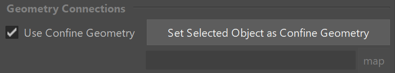
Geometry Connections

...
| Anchor | ||||
|---|---|---|---|---|
|
| Section | |||||
|---|---|---|---|---|---|
|
...
|
...
|
...
|
...
|
Use Cascade Simulator | gridUseCascade – When enabled, turns on the Cascade Connection Simulator. The liquid will be transferred from another simulator to this one in the region where both simulators intersect.
Set Selected Object as Cascade Simulator – Specifies another Phoenix Simulator which will transfer fluid to this simulator. This allows you to join several simulators into a structure with a complex shape. This can help you reduce memory usage by using many smaller simulators in place of a single large simulator. To set the Cascade simulator, select the main simulator first, then select the simulator to be used for the cascade. Then from the top Phoenix FD Menu choose Set Simulator Cascade Connection. For more information, see the Cascade tutorial for liquid simulations. For fire/smoke, see the Connecting Two Simulators in a Cascade Setup section on the Tips and Tricks page.
| UI Text Box | ||
|---|---|---|
| ||
|
...
|
| Anchor | ||||
|---|---|---|---|---|
|
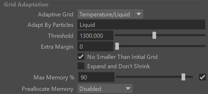
Grid Adaptation
...
| Section | |
|---|---|
|
...
|
...
|
...
|
...
|
...
|
...
|
...
|
...
|
...
|
...
|
...
|
...
|
...
|
...
|
...
|
...
|
...
|
...
|
...
|
...
|
...
|
...
|
...
|
...
|
...
|
...
|
...
|
...
|
...
|
...
|
Limited By | gridLimitedBy – Determines whether the grid's expansion is limited. If it is limited, this parameter also determines the units in which the Limited To value is expressed.
None – No limitation. If Preallocate Memory is enabled, this means all available memory can be used.
Memory – The expansion is limited by the total consumed memory. The limit is specified in percentages.
Cells – The expansion is limited by the cell count. The limit is specified in millions of cells.
Limited To | gridLimitedTo – Specifies the limit of grid expansion if Adaptive Grid or Preallocate Memory are enabled. The meaning of this value corresponds to the Limited By parameter.
...
|
...
|
...
|
...
|
...
|
...
|
...
|
...
|
...
|
...
|
...
|
...
|
...
|
...
|
...
|
...
|
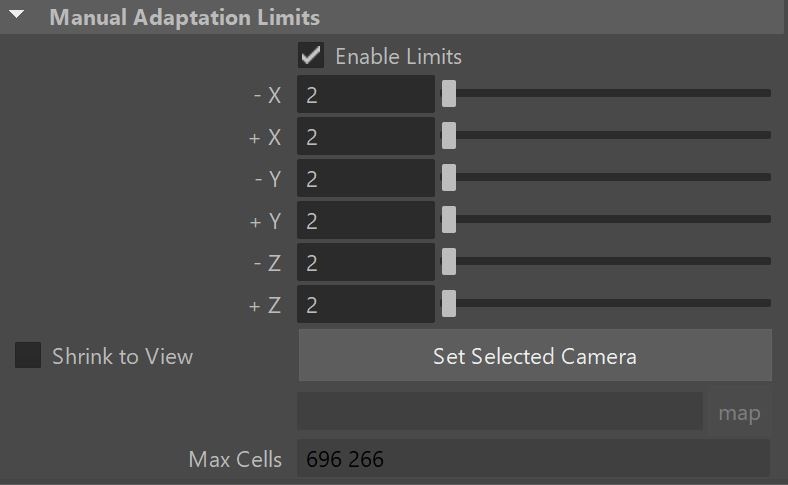
Manual Adaptation Limits
...
| Section | ||||||||||||
|---|---|---|---|---|---|---|---|---|---|---|---|---|
|
...
|
...
|
...
|
...
|
...
|
...
|
...
|
...
|
...
|
...
|
| Viewtracker | ||||
|---|---|---|---|---|
|