![]()
Page History
...
| UI Text Box | ||
|---|---|---|
| ||
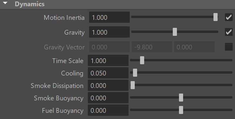
UI Path: ||Select PhoenixFDSim|| > Attribute Editor > Dynamics rollout |
Parameters
...
| Anchor | ||||
|---|---|---|---|---|
|
...
| Anchor | ||||
|---|---|---|---|---|
|
Vorticity
...
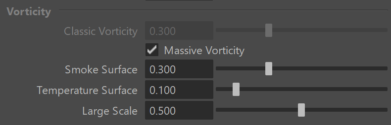
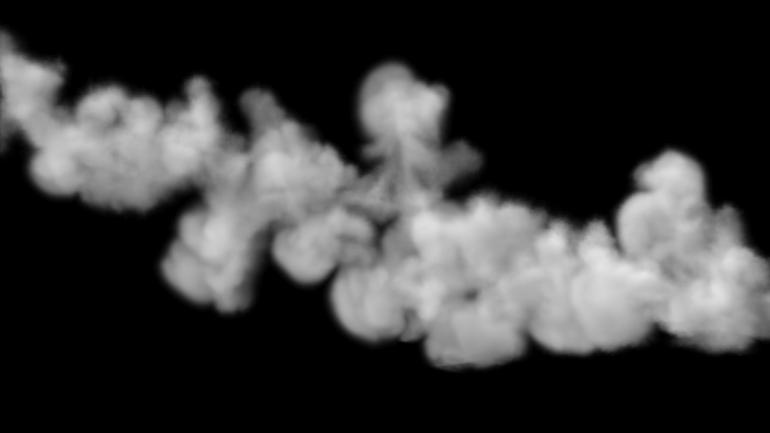
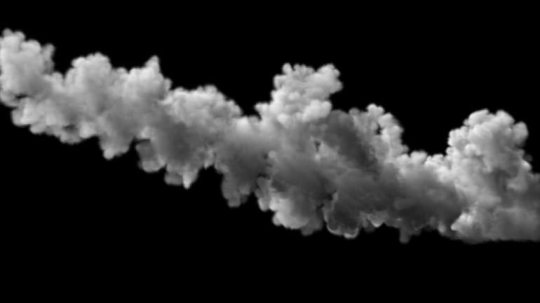
Classic Vorticity | vorticity – Adds small-scale detail that is dissipated naturally by the grid-based simulation. Prevents the simulation from becoming smooth and laminar. Unlike Turbulence, which does not care about the fluid's motion at all, the Classic Vorticity algorithms works depending on the velocity of the simulation and changes the velocity field in order to reinforce vortices and add more detail to the simulation. For more information, see the Vorticity example below.
...
These options add random fluctuations in the fluid's velocity for each grid voxel. It works in combination with the Vorticity parameters.
| UI Text Box | ||
|---|---|---|
| ||
The options in the Randomize section do not affect Liquid Simulations. |
...
Method | advMethod – Specifies the algorithm used for calculating the advection. For more information, see the Advection Method Types example below.
Backtrace (Classic) – This method has good stability, but does not strictly conserve the quantity of the transferred material and your fluid may start to gain or lose volume in certain situations. In such cases increasing the Steps per frame (SPF) will help preserve the volume.
Forward transfer – Good conservation abilities, but less stability compared to the classic method. Tends to produce cross-like artifacts.
Multi-pass Forward Transfer – Forward Transfer can help if you are losing fluid volume, but is less detailed. Multi-Pass produces the best fluid details and keeps the smoke sharp, making it best for large scale explosions and simulations when sharpness is important.
Multi-Pass – This less dissipative method produces more fine details and keeps the smoke interface sharper compared to other methods. This method is recommended for large scale explosions, veil-like smoke, pyroclastic flows, and all other situations where sharpness is important.
...
Steps Per Frame (SPF) | advSPF – Determines how many calculations the simulation grid will perform between two consecutive frames of the timeline. For more information, see the Steps per Frame examples below.
...
| Section | |||||||||||||||||||||||||||
|---|---|---|---|---|---|---|---|---|---|---|---|---|---|---|---|---|---|---|---|---|---|---|---|---|---|---|---|
Example: Advection Method Types
|
| Anchor | ||||
|---|---|---|---|---|
|
| Section | ||||||||||||
|---|---|---|---|---|---|---|---|---|---|---|---|---|
Example: Steps Per Frame (Liquid)
|
| UI Text Box | ||
|---|---|---|
| ||
Here is the difference between Steps Per Frame values of 1 and 10 when a Source emits liquid with high velocity |
| Section | ||||||||||||||||||||||||||||||||
|---|---|---|---|---|---|---|---|---|---|---|---|---|---|---|---|---|---|---|---|---|---|---|---|---|---|---|---|---|---|---|---|---|
|


| Anchor | ||||
|---|---|---|---|---|
|
| Section | ||||||||||||||||||||||||||||||||
|---|---|---|---|---|---|---|---|---|---|---|---|---|---|---|---|---|---|---|---|---|---|---|---|---|---|---|---|---|---|---|---|---|
Example: Steps Per Frame (Fire/Smoke)
|
TexUVW Control
| UI Text Box | ||
|---|---|---|
| ||
The main purpose of the Texture UVW feature is to provide dynamic UVW coordinates for texture mapping that follow the simulation. If such simulated texture coordinates are not present for mapping, textures assigned to your simulation will appear static, with the simulated content moving through the image. This undesired behavior is often referred to as 'texture swimming'. UVW coordinates are generated by simulating an additional Texture UVW Grid Channel which has to be enabled under the Output rollout for the settings below to have any effect. The custom UVW texture coordinates can be used for advanced render-time effects, such as recoloring of mixing fluids, modifying the opacity or fire intensity with a naturally moving texture, or natural movement of displacement over fire/smoke and liquid surfaces. Some examples uses are:
The Texture UVW channel values represent the UVW coordinates of each Cell in the Simulator, with a range of [ 0 - 1 ]. The channel is initialized when a simulation is started in one of two ways:
Switching to Maya Mesh mode will create a new TexUVW UV set, if you have enabled the TexUVW channel in the Output rollout before running your simulation. In order to use the new UV set you need to select the Maya Mesh and link the TexUVW UV set from the Maya Relationship editor. Switching away from the Maya Mesh mode will reset the UV sets, so if later you decide to switch back to Maya Mesh mode you will need to relink the UV set againFor more information, please check the Texture mapping, moving textures with fire/smoke/liquid, and TexUVW page. |
| UI Text Box | ||
|---|---|---|
| ||
For Fire/Smoke rendering with TexUVW coordinates, textures need to be connected the the simulator through a Maya Projection node in Perspective mode. |
Interpolation Amount | texUVWInterpol – Blends texUVWInterpol – Blends between the UVW coordinates of the liquid particle at time of birth and its UVW coordinates at the current position in the Simulator. When set to 0, no interpolation will be performed - as a consequence, textures assigned to the fluid mesh will be stretched as the simulation progresses. This is best used for simulations of melting objects. When set to 1, the UVW coordinates of the fluid mesh will be updated with a frequency based on the Interpol.Step parameter - this will essentially re-project the UVWs to avoid stretching but cause the textures assigned to the fluid to 'pop' as the re-projection is applied. If you intend to apply e.g. a displacement map to a flowing river, set this parameter to a value between 0.1 and 0.3 - this will suppress both the effects of stretching and popping. See the Interpolation example below.
Interpolation Step | texUVWInterpolStep – Specifies texUVWInterpolStep – Specifies the update frequency for the UVW coordinates. When set to 1, the UVWs are updated on every frame, taking into account the Interpolation parameterInterpolation parameter. See the Interpolation Step example below.
Antitear Strength | texUVWAntitear – texUVWAntitear – [ Only available for Fire/Smoke simulations ] Use this option when the assigned texture appears twisted, torn apart or otherwise distorted. This may happen when the simulation is moving very fast, therefore increase both the Antitear and Antitear IterationsStrength and Antitear Iterations to let Phoenix attempt to resolve the distortion.
Antitear Iterations | texUVWAntitearIterations – texUVWAntitearIterations – [ Only available for Fire/Smoke simulations ] The number of Antitear iterations Antitear iterations performed for every Step of the simulation. Increasing this parameter will help resolve UVW distortion issues by allowing Phoenix to run the Antitear operation Strength operation multiple times. Note that this may slightly increase the time it takes for the simulation to complete.
| Anchor | ||||
|---|---|---|---|---|
|
| Section | ||||||||||||
|---|---|---|---|---|---|---|---|---|---|---|---|---|
Example: Interpolation
|
| Anchor | ||||
|---|---|---|---|---|
|
| Section | ||||||||||||
|---|---|---|---|---|---|---|---|---|---|---|---|---|
Example: Interpolation Step
|