This page provides information about the Emissive material in V-Ray for Revit.
Overview
The Generic V-Ray material's Emissive preset is generally used for producing self-illuminated surfaces.

UI Options
The Emissive material settings are organized in Basic and Advanced modes. Switch the mode from the toggle button under the Preview Swatch.
Add Layer and Add Layer buttons are provided for some V-Ray materials, including Emissive. You can select an additional layer that can add up to the appearance of the material. For more information, see the Layers section and the Attributes section.
The context menu of the Color slot provides options to Copy and Paste, as well as to Reset the color.
A Reset option is provided in the context menu of each Number Slider. You can reset the slider value to the default one.
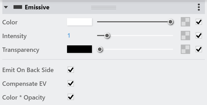
Emissive
Some options are available only in Advanced mode.
Color – Specifies the color of the light. A texture can be specified as well. See the Color and Texture examples below for more information.
Intensity – Controls the strength of the light.
Transparency – Specifies the color that is transparent. For this parameter black stands for opaque and white for transparent color. A texture can be specified as well. See the Transparency Texture example below for more information.
Emit On Back Side – When enabled, the object emits light from its back side as well. When disabled, only the front side emits light, and the material renders as black on the back sides. See the Emit On Back Side examples below for more information.
Compensate EV – Used when rendering with the V-Ray Physical Camera. When enabled, the intensity of the material is adjusted to compensate for the camera exposure.
Color *Opacity – When enabled, the color of the light material is multiplied by the opacity texture. Otherwise, the color and opacity act independently (so-called additive transparency).
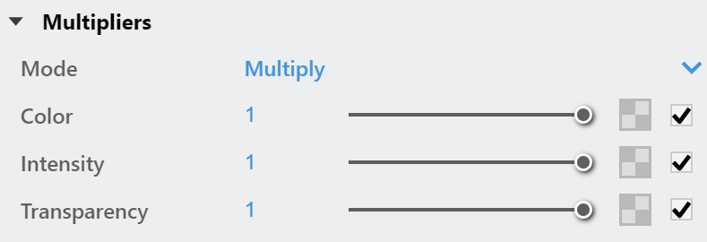
Multipliers
This rollout is available only in Advanced mode.
Mode – Specifies one of the following methods for adjusting textures.
Multiply – Multipliers can be specified to adjust colors and textures.
Blend Amount – Blend amounts can be specified to adjust colors and textures.
Color – Controls the intensity of the Emissive Color (light color).
Intensity – Controls the strength of the light.
Transparency – Controls the intensity of the Transparency Color, which determines the color that is transparent.
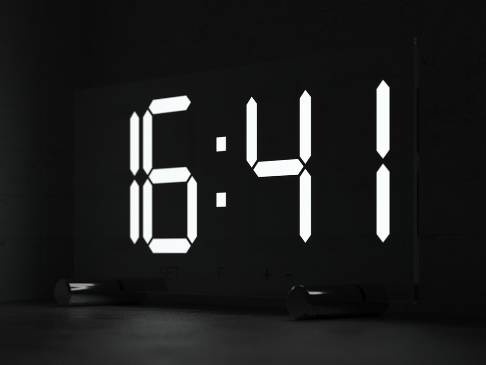
Example: Color and Texture, Intensity, Emit On Back Side
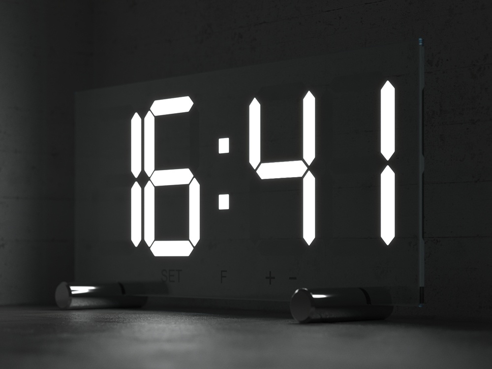
Here are some examples showing the difference in Intensity, the Emit On Back Side turned on and off and using an image in the Color Texture slot.
Intensity: 1
Color: White
Emit On Back Side: Off
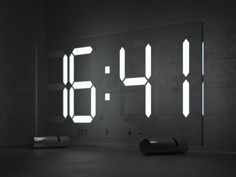
Intensity: 5
Color: White
Emit On Back Side: Off
Intensity: 1
Color: White
Emit On Back Side: On
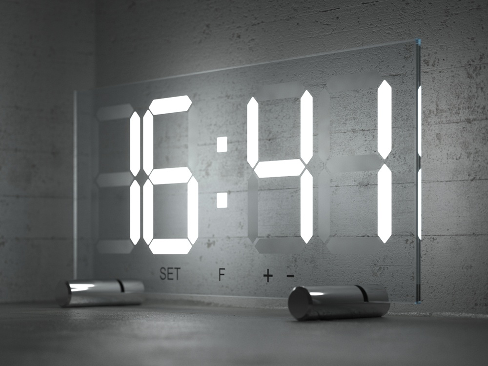
Intensity: 5
Color: White
Emit On Back Side: On
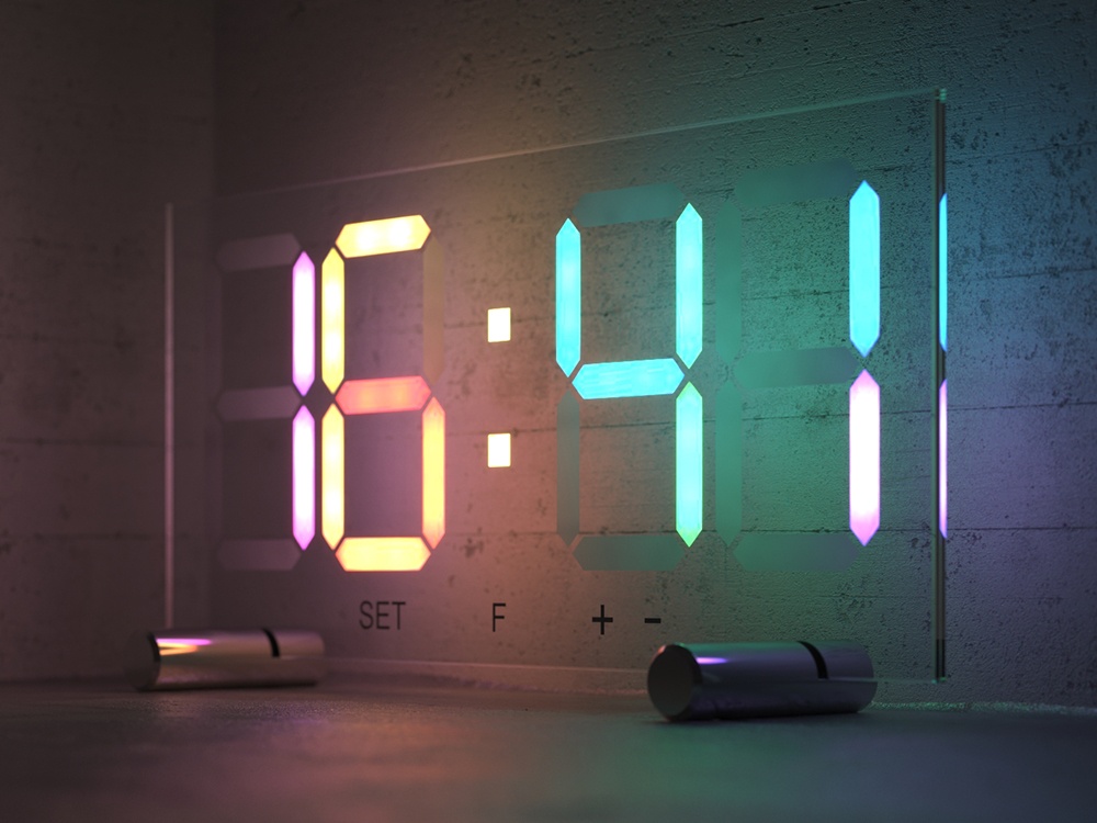
Intensity: 5
Image loaded in the Color Texture slot.
Emit On Back Side: on
Transparency Texture On/Off
This example shows the usage of an image in the Transparency Texture slot. Both renders have the Emit On Back Side function turned on as well.
![]()
Intensity: 10
Color: Blue
Override Control

Attributes
The attributes from the following expandable menus are available for the Emissive material.
Translucency
Back Material – Defines the material V-Ray uses for back side faces as defined by their normals.
Translucency – Determines if the front or the back side of the material is more visible in the rendering process. By default this value is 0.5, which means that both sides are equally visible. When the value is closer to zero, the material facing the camera is more visible, when it is closer to 1, the back material is more visible. A texture can be used to control the variation of the effect.
Mult. by Front Diffuse – When enabled, the translucency is multiplied by the diffuse of the front material.
![]()
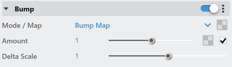
Bump
Mode/Map – Specifies the bump map type.
Bump Map – A height map should be used.
Bump Texture Channel – Some V-Ray textures have a special bump channel output that can be used here. It is most commonly used for Round Edges effect. Edges texture is used as a bump.
Normal Map – RGB normal map should be used with this option. Note that in most cases the normal map bitmap color space should be set to Linear to ensure correct results.
Amount – Multiplier for the bump/normal map.
Delta Scale – Specifies a scale for sampling the bitmap when using bump mapping. The exact value is calculated automatically by V-Ray, but can be called here.
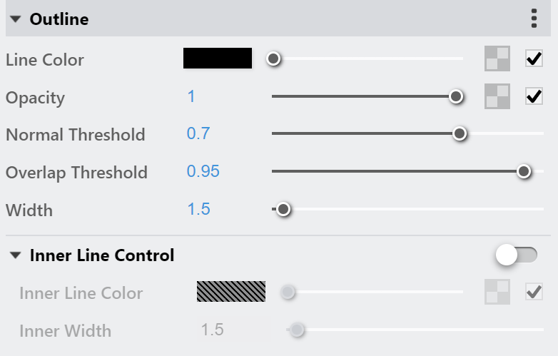
Outline
The Outline attribute is available only when the engine is set to CPU. It is currently not supported for GPU.
Line Color – Specifies the color of the outlines.
Opacity – Specifies the opacity of the outlines.
Normal Threshold – Determines when lines will be created for parts of the same object with varying surface normals (e.g. at the inside edges of a box). A value of 0.0 means that only 90 degrees or larger angles generate internal lines. Higher values mean that smoother transitions between face normals can also generate a line. Setting this value to 1.0 fills curved objects completely.
Overlap Threshold – Determines when outlines will be created for overlapping parts of the one and the same object . Lower values reduce the internal overlapping lines, while higher values produce more overlap lines. Setting this value to 1.0 fills curved objects completely.
Width – Specifies the width of the outlines.
Inner Line Control – Enables a separate control for the inner edges.
Inner line Color – Specifies the color of the inner lines
Inner Width – Specifies the width of the inner lines.
Some of the global parameters have an effect on all materials with Outline attribute. These parameters are Width Type, Trace Bias, No Inner Edges, Visible in Secondary, and Compensate EV.
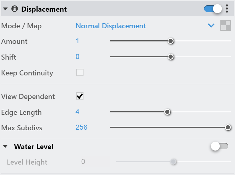
Displacement
This is a legacy attribute that will be removed in the future. Consider using the geometry displacement modifier instead. It can be created as a geometry asset in the Outliner and can be applied to objects in the project. Note that the displacement effect will no longer appear in the Preview Swatch.
Displacement – Enables or disables the displacement effect.
Mode / Map – Specifies the mode in which the displacement is rendered.
2D Displacement – Bases the displacement on a texture map that is known in advanced. The displaced surface is rendered as a warped height-field based on that texture map. The actual raytracing of the displaced surface is done in texture space and the result is mapped back into 3D space. The advantage of this method is that it preserves all details in the displacement map. However, it requires the object to have valid texture coordinates. You cannot use this method for 3d procedural textures or other textures that use object or world coordinates. The parameter can take any values.
Normal Displacement – Takes the original surface geometry and subdivides its triangles into smaller sub-triangles, which then are displaced.
Amount – The amount of displacement. A value of 0.0 means the object appears unchanged. Higher values produce a greater displacement effect. This parameter can also take a negative value, in which case the displacement pushes geometry inside the object.
Shift – Specifies a constant, which is added to the displacement map values, effectively shifting the displaced surface up and down along the normals. This can be either positive or negative.
Keep Continuity – When enabled, tries to produce a connected surface, without splits, when there are faces from different smoothing groups and/or material IDs. Note that using material IDs is not a very good way to combine displacement maps since V-Ray cannot always guarantee the surface continuity. Use other methods (vertex colors, masks etc.) to blend different displacement maps.
Resolution – (Available when the Mode/Map is 2D Displacement) Determines the resolution of the displacement texture used by V-Ray. If the texture is a bitmap, it is recommended to match this resolution to the size of the bitmap. For procedural 2D maps, the resolution is determined by the desired quality and detail in the displacement. Note that V-Ray also automatically generates a normal map based on the displacement map in order to compensate for details not captured by the actual displaced surface.
View Dependent – When enabled, Edge length determines the maximum length of a subtriangle edge in pixels. A value of 1.0 means that the longest edge of each subtriangle is about one pixel long when projected on the screen. When disabled, Edge length is the maximum sub-triangle edge length in world units.
Edge Length – Determines the quality of the displacement. Each triangle of the original mesh is subdivided into a number of subtriangles. More subtriangles mean more detail in the displacement, slower rendering times and more RAM usage. Less subtriangles mean less detail, faster rendering and less RAM. The meaning of Edge length depends on the View dependent parameter. The slider's minimum range is set to 0.4. Using lower values is still possible by manually typing them in the input box but it may cause significant render delay.
Max Subdivs – Controls the maximum sub-triangles generated from any triangle of the original mesh when the displacement type is Subdivision. The value is in fact the square root of the maximum number of subtriangles. For example, a value of 256 means that at most 256 x 256 = 65536 subtriangles will be generated for any given original triangle. It is not a good idea to keep this value very high. If you need to use higher values, it will be better to tessellate the original mesh itself into smaller triangles instead. The actual subdivisions for a triangle are rounded up to the nearest power of two (this makes it easier to avoid gaps because of different tessellation on neighboring triangles).
Water Level – Clips the surface geometry in places where the displacement map value is below the specified threshold. This can be used for clip mapping a displacement map value below which geometry will be clipped.
Level Height – Value below which the geometry is clipped.
Materials need to be applied to objects (groups/components) to have working displacement. If various materials are applied to different faces of an object, the displacement from the top-level (group/component) material will be used on all of them. Normal Displacement will take into account the texture size of each different face material, while 2D Displacement will ignore them.
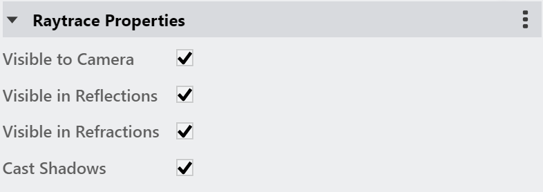
Raytrace Properties
Visible to Camera – When enabled, makes objects using this material visible to the camera.
Visible to Reflections – When enabled, makes objects using this material visible for to Reflection rays.
Visible to Refractions – When enabled, makes objects using this material visible for the Refraction rays.
Cast Shadows – When disabled, all objects with this material applied do not cast shadows.
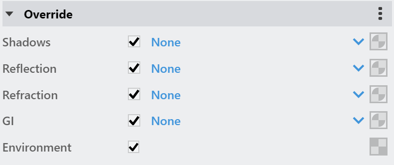
Override
Shadows – The material that is used when a shadow ray hits the surface.
Reflection – The material that is used when a reflection ray hits the surface.
Refraction– The material that is used when a refraction ray hits the surface.
GI – The material that is used when a GI ray hits the surface.
Environment – The texture that will be used instead of the scene environment maps.
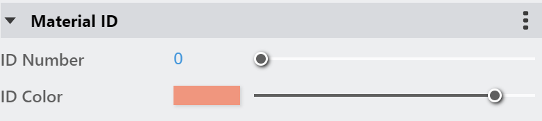
Material ID
ID Number – Isolates objects as an R/G/B mask in the MultiMatte Material render elements.
ID Color – Specifies a color to represent this material in the Material ID VFB render element.
Each material is assigned with an automatically generated ID Color.
Layers
The Layers available for the Emmisive material are as follows.
VRay Mtl
Emissive
Diffuse Coat
Reflective Coat
Flakes 2
Stochastic Flakes
Notes
- You can use the Emissive material as a light source assigned to an object. Increasing the Value of the color affects the GI solution and produces more light. Note that overbright colors may look the same as pure white but the GI results is different.
- If you know the photometric power of a self-illuminated object in lumens (e.g. 1700 lm for a 100-watt bulb) you can calculate the multiplier for the Emissive material if you divide the lumens by the surface area of the object in meters, provided that the self-illuminated color is pure white.
- The direct illumination options currently only work properly if the Emissive material is the only material applied on the object. They will not work if the material is part of a complex material like a Blend material. This restriction will probably be removed in a future release.