This page provides information about V-Ray Decal in V-Ray for Revit.
Overview
V-Ray Decal provides an easy way to project one material on top of another.
In Revit, it is represented by a parametric box-shaped family which provides control over the projection size, limits and direction, as well as the order in case of multiple decals overlapping. The projection can utilize either a native Revit material or a V-Ray one. The V-Ray Decal can be projected on top of any Revit surface regardless of its category and shape, as well as to multiple surfaces at once. The projection itself is visible only at render time.
UI Path
||Revit Ribbon|| > V-Ray tab > Assets panel > Place Decal button > choose the type of the Decal projector box family to be created > On Level (creates a level-based family), On Face (creates a face-based family)
Workflow
The V-Ray Decal in Revit is represented by a native Revit box-shaped family of the Generic category which we call a projector box.
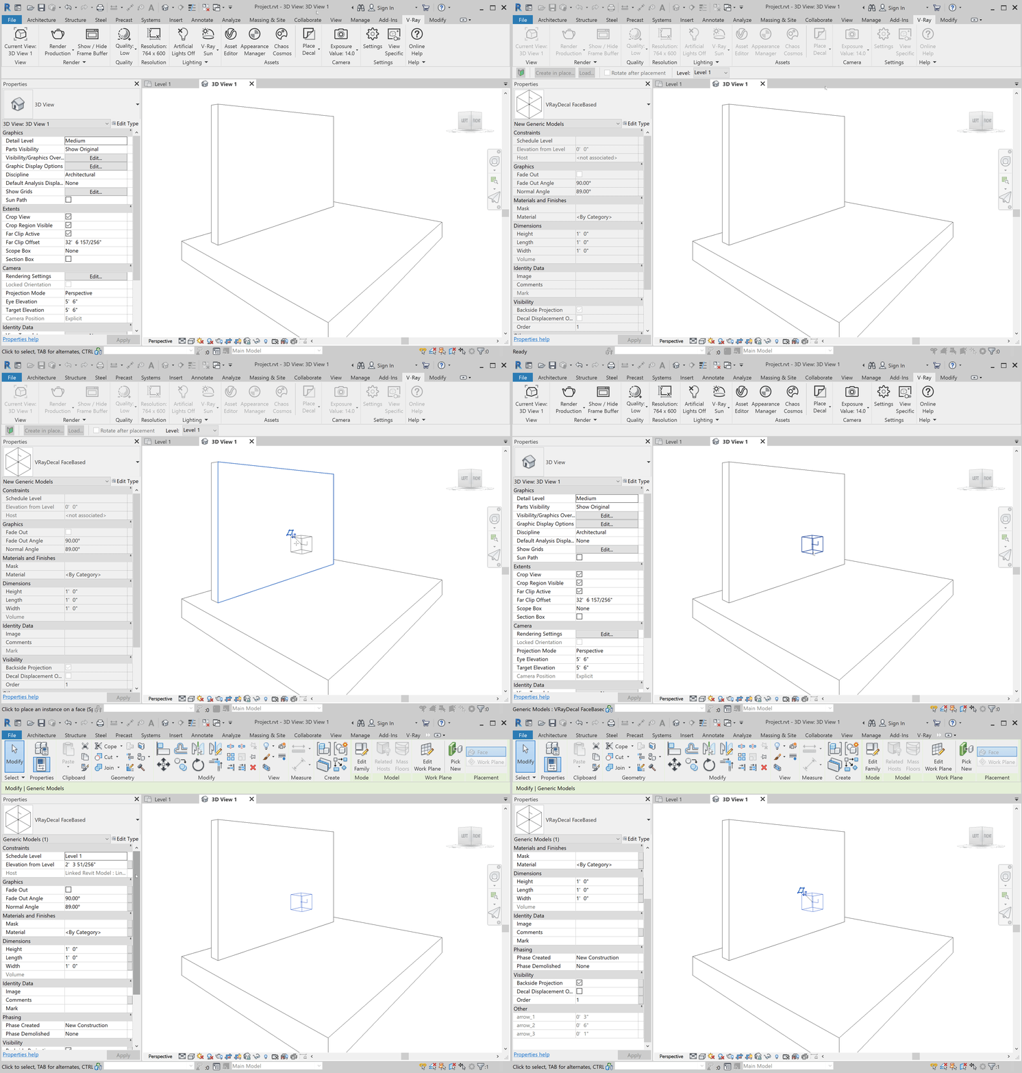
To create a decal, click on the Decal toolbar button and choose the type of placement for the projector box. You can select between the standard level-based placement (On Level) or a face-based one (On Face).
Upon selection, the component placement mode of Revit is activated and you can place a single or multiple instances of the generated VRay Decal family.
- If level-based family is used, it needs to be positioned so that its volume intersects with the surface(s) towards which the decal is projected.
- If face-based family is used, the decal is projected on its host surface.
Within the projector box family, there is an arrow indicating the direction towards which the decal is projected. That direction is fixed towards the host surface in case of face-based projector box, whereas in case of level-based projector box, it can be modified with the help of the Projection direction family parameter.
The vertical line at the beginning of the arrow indicates where the top direction of the decal texture is.
The decal is projected onto all object surfaces that face its projection direction and are positioned within the projector box. In case you want to exclude some of them from the projection, you can create a Revit model group including the decal and the geometries you want it projected onto.
While the decal projector box, as a native Revit family, is an actual part of the Revit model, hence visible across all views (unless hidden/filtered), the projection effect is visible only at render time. A variety of visual aspects related to the projection, such as its size, position order, angle of projection etc., can be adjusted using the family parameters of the projector box.
Parameters
The size of the projection matches the size of the projector box. To adjust it, use the family Dimensions as follows:
Height – Specifies the height of the cube which also defines the depth of the V-Ray Decal projection. Based on the projection direction, the Decal material is projected on all surfaces intersecting with the cube along its height.
Length – Specifies the length of the cube which equals the length of the V-Ray Decal projection.
Width – Specifies the width of the cube which equals the width of the V-Ray Decal projection.
To specify the material that will be used for the projection and whether it will be projected in a specific shape, use the parameters under the Materials and Finishes section.
Material – Specifies the material projected via the V-Ray Decal. By default, you will be prompted to select a Revit material. To use a V-Ray material, find the Revit material in the V-Ray Appearance Manager Materials list and replace it with a V-Ray one. Read more about material replacements here.
Mask – A texture which masks the projected material in a specific shape. To assign a mask, create a texture from the texture menu in the V-Ray Asset Editor, then type its name in this field.
To control the projection fade (which is handy when projecting on curvy surfaces) or the direction in which the decal is projected, use the Graphics section parameters as follows:
Projection Direction - Specifies the direction in which the V-Ray Decal is projected.
- 1 - Top-Bottom (default)
- 2 - Side
- 3 - Bottom-Top
Higher or lower values automatically set the projection to its default value of 1.
Fade Out – Enables the fade out effect. Enabling this setting applies the Fade Out Angle value when projecting the decal.
Fade Out Angle – Specifies the angle where the decal projection fades out. For the fade out effect to be visible, keep that angle wider than the Normal Angle. Both angles determine the start and end points of the decal projection onto the surface.
Normal Angle – Limits the Decal projection based on the angle between the target surface and the projection direction.
To control whether the decal contains displacement, whether it is visible on the backside of single-surface objects as well as the order of overlapping decals, use the Visibility section parameters as follows:
Backside Projection – When enabled, the V-Ray Decal is also projected on the back side of the object. Note that additional adjustment to the Normal Angle might be needed.
Decal Displacement – When enabled, the V-Ray Decal ignores the displacement of the surface and would use only its own displacement if present.
Order – Specifies a layering order when multiple V-Ray Decal families are present and intersect with each other.
Notes
- Native Revit RPCs are not compatible with the V-Ray Decal. Make sure they are excluded from the V-Ray Decal's projection.


