This page contains information about the V-Ray MetaImageFile node.
Overview
The V-Ray MetaImageFile node is used to load a variety of image files.

Bitmap
File – Specifies the file name to load. The name can contain <UDIM> or <UVTILE> tags for Mari or Mudbox tiles respectively, or $nU and $nV for explicit tiles. Note that lower-case tags consider the tiles as starting from 0 whereas upper-case tags start from 1.
V-Ray supports custom attributes in the File parameter, provided the attribute is specified either on the Geometry node itself, or placed on individual packed primitives. You can modify the File path with a custom string attribute "s@tex" with the following notation: "$HIP/texture_000<tex>.jpg".
When using this workflow, be sure to force V-Ray to export the attribute from the V-Ray Object Properties of the rendered object.
Filter – Specifies the type of filtering to apply to the image.
None – Does not apply any filtering.
Nearest – The nearest texel from the map is taken, without any interpolation.
Mip-Map – Applies a mip-map filter.
Area – Applies an anti-aliasing area filter.
Elliptical – High quality anisotropic MIP map texture filtering that reduces blurring and aliasing artifacts.
Sharp Mip-Map – Default filtering used in 3ds Max.
Interpolation – Specifies the interpolation method when using Mip-Map filtering.
Bilinear – Image values are interpolated from four pixels in the bitmap. This is the fastest interpolation method, but the result is not continuous (non-smooth) and may produce artifacts when the map is used for displacement or bump mapping.
Bicubic – Image values are interpolated from sixteen pixels in the bitmap. This is the slowest method, but the results are smooth without too much blur;
Quadratic – Image values are interpolated from nine pixels in the bitmap. This method is faster than the Bicubic interpolation, but may smooth the image too much.
Blur – Specifies the strength of the blur filter applied to the bitmap.
Transfer Function – Specifies the transfer function color space for the loaded image file.
None – No correction is applied.
Inverse Gamma – The transfer function color space is controlled through the Gamma parameter.
sRGB – The loaded image is considered in sRGB transfer function color space.
Auto – Automatically determines the color transfer function. If a bitmap file name contains the string "_srgb" the transfer function is sRGB. If a bitmap file name contains the strings "_lin_srgb" or "raw", no correction is applied. For bitmap files with 8 bits per color component and 3 or 4 color components (like png, jpg and other), the transfer function is sRGB. In all other cases, no correction is applied.
Gamma – A gamma–correction value for the image when the Transfer Function is set to Inverse Gamma. For example, if the bitmap was saved to disk with a 2.2 gamma correction, you need to enter 0.4545 to remove that correction for the rendering.
RGB Primaries – Allows for manual override of the RGB primaries of the bitmap.
Raw – No transformation is applied to R|G|B colors. This option is suitable for normal maps;
sRGB – The loaded image is considered in sRGB color space;
ACEScg – The loaded image is considered in ACEScg color space.
Allow Negative Colors – When disabled, negative colors are clamped. Enable to allow negative colors.
Use Data Window – When enabled, takes the data window information, e.g. in OpenEXR files.
Override Frame Number
Enable – Enables the use of frame number overrides.
Playback Type – Controls what happens when the last frame of the animated texture is reached. The available options are:
Linear
Loop – The animation starts again from the frame specified in the Start option;
Ping-Pong – The animation is played backwards until it reaches the frame specified in the Start option and then play forward again;
Hold – The animation stops at the last frame and it is displayed until the end of the scene animation.
Range
Start – Specifies the beginning of the texture animation. The frame number specified here is played at the first frame of the scene animation.
Offset – Specifies the number of frames shifted between the animation and the time range.
Speed – Specifies the pace at which the animation plays. The default of 1 plays at the speed for which the animation was created.
Length – Specifies the number of frames used to play the animation.

Texture
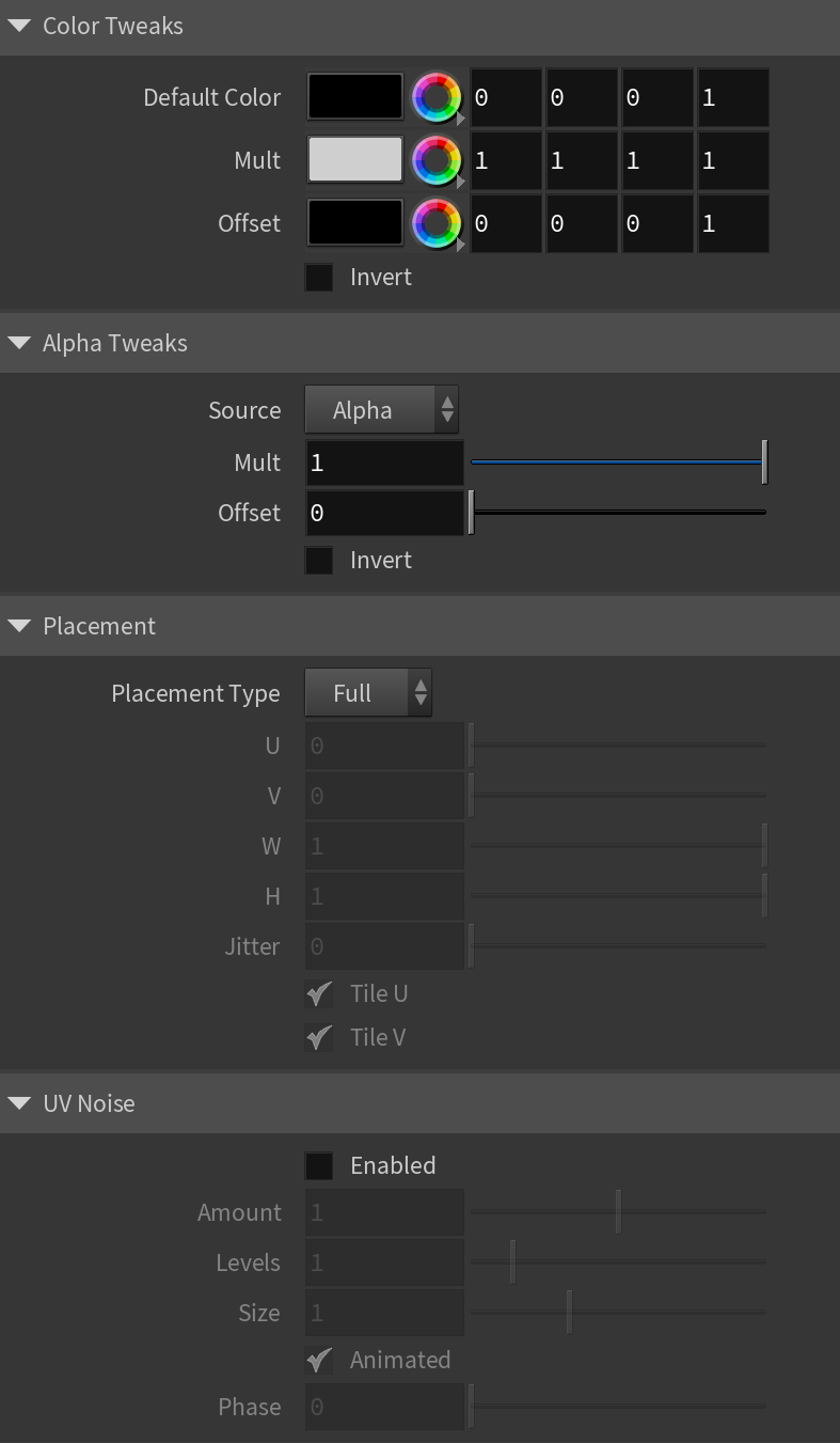
Color Tweaks
Default Color – Specifies a color when there are no valid uvw coordinates.
Mult – Specifies a multiplier for the texture color.
Offset – Color corrects the texture by adding the RGB color values specified here to the RGB color values in the texture.
Invert – When enabled, inverts the resulting texture color.
Alpha Tweaks
Source – Specifies where the alpha channel is drawn from.
Alpha – Alpha channel is drawn from the texture.
Color – Alpha is generated from pixel intensity.
Opaque – Alpha channel is fully opaque.
Use – Differentiates between textures exported from different applications: Color Intensity (3ds Max) or Color Luminance (Maya).
Mult – Specifies a multiplier for the texture alpha.
Offset – Specifies an additional offset for the texture alpha.
Invert – When enabled and Invert from Color Tweaks is also enabled, the resulting texture alpha is inverted as well.
Placement
Placement Type – Specifies the way the valid portion of the texture is applied.
Full – Uses the full valid portion of the texture.
Crop – Specifies a section of the texture using the parameters below.
Place – Specifies a section of the texture and how to place is using the parameters below.
U – Specifies the U coordinate of the valid texture sector.
V – Specifies the V coordinate of the valid texture sector.
W – Specifies the width of the valid texture sector.
H – Specifies the height of the valid texture sector.
Jitter – Controls the amount of random placement variation.
Tile U – Enables horizontal tiling.
Tile V – Enables vertical tiling.
UV Noise
Enabled – Enables noise for the texture.
Amount – Specifies the amount of noise to add to the texture.
Levels – Specifies the amount of noise iterations.
Size – Controls the scale of the noise.
Animated – Enables the noise to be animated.
Phase – Controls the noise phase.
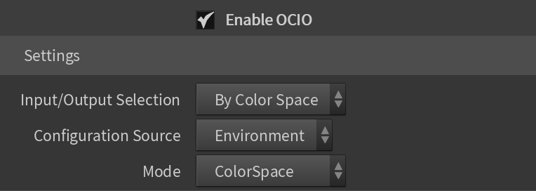
OCIO
Enable OCIO – Enables OCIO.
Input/Output Selection – Determines how the input and output color spaces are specified.
By Color Space – Specifies the input and output color spaces directly.
By Role – Specifies the input and output color space depending on the task you want to perform as defined in the OCIO configuration.
Configuration Source – Manually specifies an OCIO configuration. If not specified, the OCIO environment variable is used.
Config File – Specifies an OCIO configuration file.
Mode – Specifies what color transformations are performed:
ColorSpace – The texture performs color space conversions.
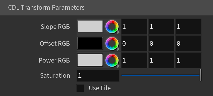
CDL Transform – The texture performs an ASC CDL transformation. CDL stands for "Color Decision List", which is a color grading information exchange format developed by the ASC (American Society of Cinematographers).
File Transform – The texture performs a color transformation based on another file (i.e. .3dl, .lut, .cube etc).
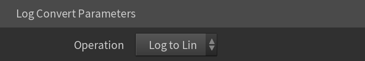
LogConvert – The texture performs log2lin or lin2log conversion.
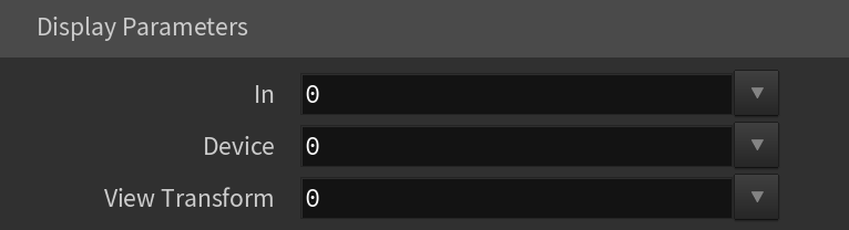
Display – The texture performs color space conversion for display.
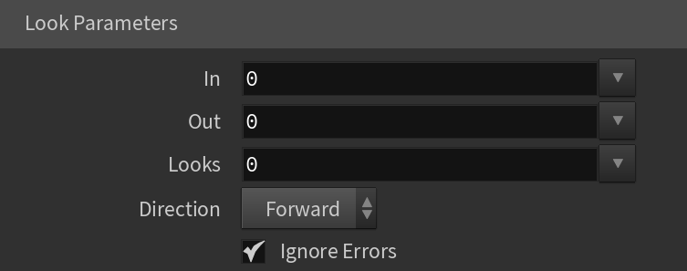
Look – The texture performs a look transform. The OCIO config must define looks for this mode to work.
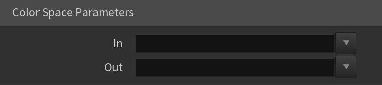
In – Specifies the input color space (the color space that the input texture is in).
Out – Specifies the output color space (for rendering, this would typically be a linear color space).
Slope RGB – Specifies multipliers for the red/green/blue color components.
Offset RGB – Specifies offsets for the red/green/blue color components.
Power RGB – Specifies gamma values for the red/green/blue color components.
Saturation – Saturation value. A value of 0.0 makes the image grayscale.
Use File – When enabled, the CDL parameters are read from a .cc or a .ccc file instead of specified directly.
Color Correction File – Specifies a .cc or .ccc file to read.
Color Correction ID – Specifies the color correction ID as specified in the color correction file.
Direction – Specifies whether the forward or the inverse CDL transformation is applied.
File – Specifies a color transformation file (.3dl, .cube, .lut, etc.).
Color Correction ID – Specifies the color correction ID if present in the file.
Direction – Specifies whether forward or inverse color transformation should be applied. Not all file formats support inverse transformations.
Interpolation – If the file contains tabulated data (i.e. .cube files), specifies how this data is interpolated.
Nearest – No interpolation. The nearest suitable color from the table is picked up. This method is fast, but may introduce artifacts, especially in textures with smooth gradients.
Linear – The color is linearly interpolated from the nearest values in the table. This is a smooth method, but is slower than nearest.
Tetrahedral – Uses the tetrahedral method to convert colors with high accuracy.
Best – Chooses the best interpolation method for the requested context.
![]()
Operation – Specifies whether to convert from linear to log space or vice versa.
In – Specifies the color space of the base texture.
Device – Specifies a viewing device from the devices listed in the OCIO configuration.
View Transform – Specifies the desired view transformation.
In – The color space of the base texture.
Out – The output color space.
Looks – The name of the look if the OCIO configuration defines looks.
Direction – Specifies whether to apply forward or inverse transformation.
Ignore Errors – When enabled, attempts to perform color corrections even if there are errors.
UV
Main
Type – Specifies how to generate or use the existing UV attribute.
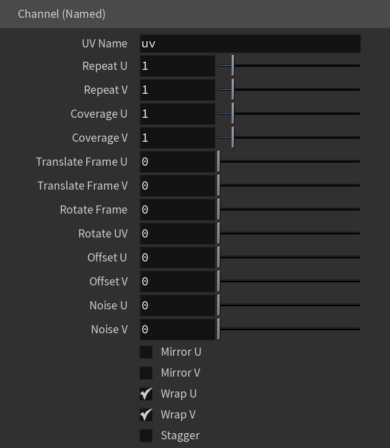
Channel (Named) – Specifies the name of the UV attribute.
Environment
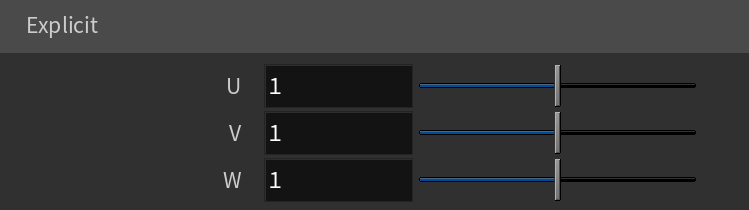
Explicit
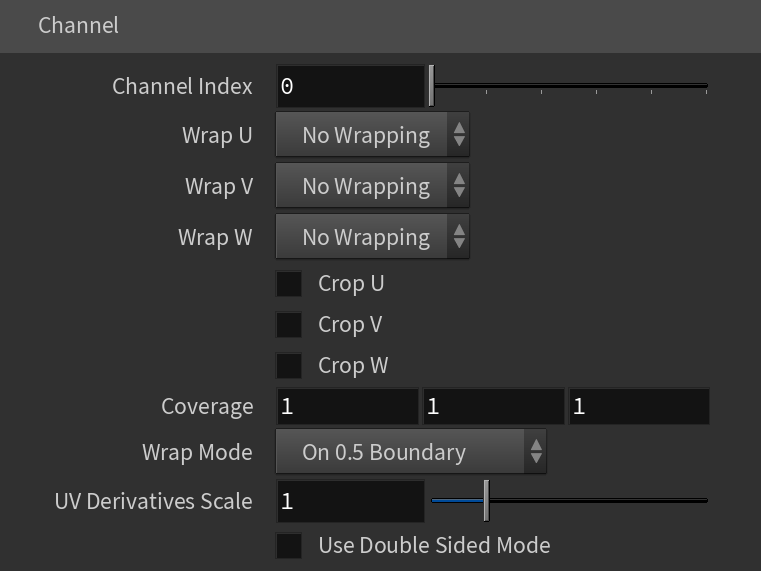
Channel
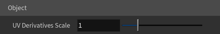
Object
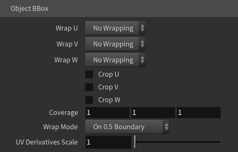
Object BBox
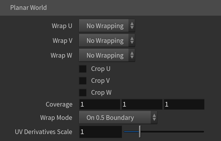
PlanarWorld
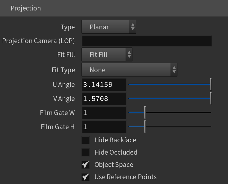
Projection

UV Name – The name of the UV channel that is used.
Repeat U – Multiplier for U values.
Repeat V – Multiplier for V values.
Coverage U – U values are remapped to 1.0.
Coverage V – V values are remapped to 1.0.
Translate Frame U – Translates the frame in U direction after applying rotate_frame (and before wrap, coverage, clamp).
Translate Frame V – Translates the frame in V direction after applying rotate_frame (and before wrap, coverage, clamp).
Rotate Frame – Rotates the frame after applying UV noise.
Rotate UV – Rotates the UVs after mirroring.
Offset U – Offset added to U before mirroring (after wrap, coverage, clamp).
Offset V – Offset added to V before mirroring (after wrap, coverage, clamp).
Noise U – Noise magnitude multiplier in U direction.
Nose V – Noise magnitude multiplier in V direction.
Mirror U – When enabled, every other tile outside the [0;1] range is mirrored in U.
Mirror V – When enabled, every other tile outside the [0;1] range is mirrored in V.
Wrap U – When enabled, U values outside the [0;1] range wrap back to [0;1].
Wrap V – When enabled, V values outside the [0;1] range wrap back to [0;1].
Stagger – When enabled, tiles in the V direction add +0.5 to the U value for a 'staggering' effect.
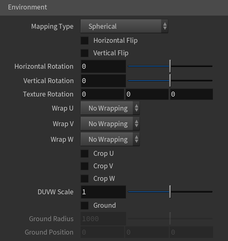
Mapping Type – Specifies the type and shape of the texture among Spherical, Angular, Cubic, Mirror Ball and Screen.
Horizontal Flip – Flips the environment horizontally.
Vertical Flip – Flips the environment vertically.
Horizontal Rotation – Specifies the horizontal rotation (left and right).
Vertical Rotation – Specifies the vertical rotation (up and down).
Texture Rotation – Specifies the texture rotation.
Wrap U – If true, U values outside the [0;1] range wrap back to [0;1]. You can choose between the No Wrapping, Wrap and Mirror Tile options.
Wrap V – If true, V values outside the [0;1] range wrap back to [0;1]. You can choose between the No Wrapping, Wrap and Mirror Tile options.
Wrap X – If true, X values outside the [0;1] range wrap back to [0;1]. You can choose between the No Wrapping, Wrap and Mirror Tile options.
Crop U – When enabled, crops in the U direction.
Crop V – When enabled, crops in the V direction.
Crop W – When enabled, crops in the W direction.
DUVW Scale – Additional scale factor for the texture derivatives.
Ground – Enables ground projection of the texture.
Ground Radius – Specifies a projection radius. Can be used to control the scale of the projection.
Ground Position – Ground projection center position when ground_on=1.
U – Specifies an explicit U input to replace the U value from shaded geometry.
V – Specifies an explicit V input to replace the V value from shaded geometry.
W – Specifies an explicit W input to replace the W value from shaded geometry.
Channel Index – Index of the mapping channel that is used.
Wrap U/V/W – If true, U/V/W values outside the [0;1] range wrap back to [0;1]. You can choose between the No Wrapping, Wrap and Mirror Tile options.
Crop U – When enabled, crops in the U direction.
Crop V – When enabled, crops in the V direction.
Crop W – When enabled, crops in the W direction.
Coverage – Specifies the uvw coordinates for the specified channel at the current shading point.
Wrap Mode – Specifies the wrap mode. You can choose between On 0.5 Boundary and On Integer Boundary.
UV Derivatives Scale – Additional scale factor for the texture derivatives.
Use Double Sided Mode – When enabled, the uvw_channel is used for front-side and uvw_channel+1 is used for back-side contexts.
UV Derivatives Scale – Additional scale factor for the texture derivatives.
Wrap U/V/W – If true, U/V/W values outside the [0;1] range wrap back to [0;1]. You can choose between the No Wrapping, Wrap and Mirror Tile options.
Crop U/V/W – When enabled, crops in the corresponding direction.
Coverage – Specifies the uvw coordinates for the specified channel at the current shading point.
Wrap Mode – Specifies the wrap mode. You can choose between On 0.5 Boundary and On Integer Boundary.
UV Derivatives Scale – Additional scale factor for the texture derivatives.
Type – Specifies the mapping type.
None
Planar
Spherical
Cylindrical
Ball
Cubic
Tri-Planar
Perspective
Projection Camera – Specifies which camera to be used when the Perspective mode is selected.
Projection Camera (LOP) – Same as Projection Camera parameter but for use in the LOP context.
Fit Fill – Specifies how the projection is fitted.
Fit Fill – Fitted to fill the space.
Horizontal – Fitted horizontally.
Fit Fill – Specifies how to fit the projection. You can choose from Fit Fill, Vertical and Horizontal.
Fit Type – Specifies the fit type from None, Match Camera Film Gate, and Match Camera Resolution options.
U Angle – Specifies the angle that corresponds to U=1 when the Spherical mode is selected.
V Angle – Specifies the angle that corresponds to V=1 when the Spherical mode is selected.
Film Gate W – Specifies the film gate width when the Perspective mode is selected.
Film Gate H – Specifies the film gate height when the Perspective mode is selected.
Hide Backface – When disabled, it projects on back faces of polygons when the Perspective mode is selected. Enable to ignore back faces projection.
Hide Occluded – When disabled, it projects on occluded points when the Perspective mode is selected. Enable to ignore occluded points projection.
Object Space – When enabled, the projection is applied in the object space of the currently shaded geometry.
Use Reference Points – Uses reference mesh/rest inputs for projection calculations.
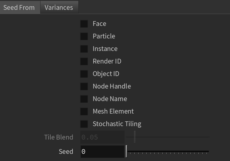
Randomize
Enable Randomizer – Enables UV Randomization.

Face – Considers the face IDs of the object when feeding the data (color or texture) to the material.
Particle – Assigns random colors based on ParticleID.
Instance – Assigns random colors based on InstanceID (works for Alembic instances and VRayInstancer source objects).
Render ID – Assigns random colors based on RenderIDs.
Object ID – Considers the Object IDs of the object when feeding the data (color or texture) to the material.
Node Handle – Each node in Houdini is assigned a unique number (a handle) when it is created. This option generates the color index based on that node ID. It is useful because the node handle survives through scene editing - e.g. if you add/remove other objects, or rename them, you still get the same colors.
Node Name – Generates a color index based on the name of the node that the texture is applied to. This allows the color to remain consistent if the object is merged into another scene, or X-Ref'd, etc.
Mesh Element – Assigns random colors based on element (e.g. teapot lid, etc.) IDs of the object;
Stochastic Tiling – Changes the mapping based on the UV tile.
Tile Blend – Edge blending between adjacent tiles when UV Tile is enabled.
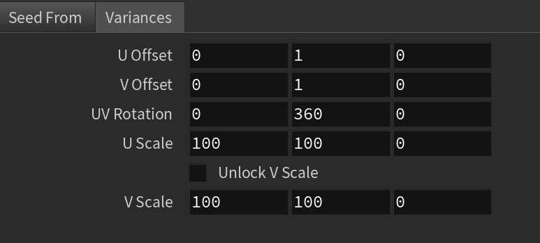
Seed – Changes the randomization pattern.
U/V Offset – Controls the position of the texture along the U or V axis.
UV Rotation – Rotates the texture along the U or V axis.
U Scale – Scales the texture along the U axis.
Unlock V Scale – When enabled, the V scale has variance. When disabled, the V scale is the same as the U scale.
V Scale – Scales the texture along the V axis.