Note that we avoid generating a large number of splash particles in the initial frames. This page offers a guide on how to create a splashy whale jumping simulation with Phoenix for 3ds Max.
Overview
This advanced level tutorial guides you through the workflow for setting a whale jumping simulation using Chaos Phoenix. It's recommended that you have at least basic knowledge in lighting and materials in 3ds Max.
To follow the steps of this tutorial, the minimum requirements are Phoenix 5.20.02 Nightly, Build from 24th of November 2023 and V-Ray 6 Update 2 Official Release for 3ds Max 2020 at least. You can download nightlies from https://nightlies.chaos.com and get the latest official V-Ray from https://download.chaos.com. If you notice a major difference between the results shown here and the behavior of your setup, please reach us using the Support Form.
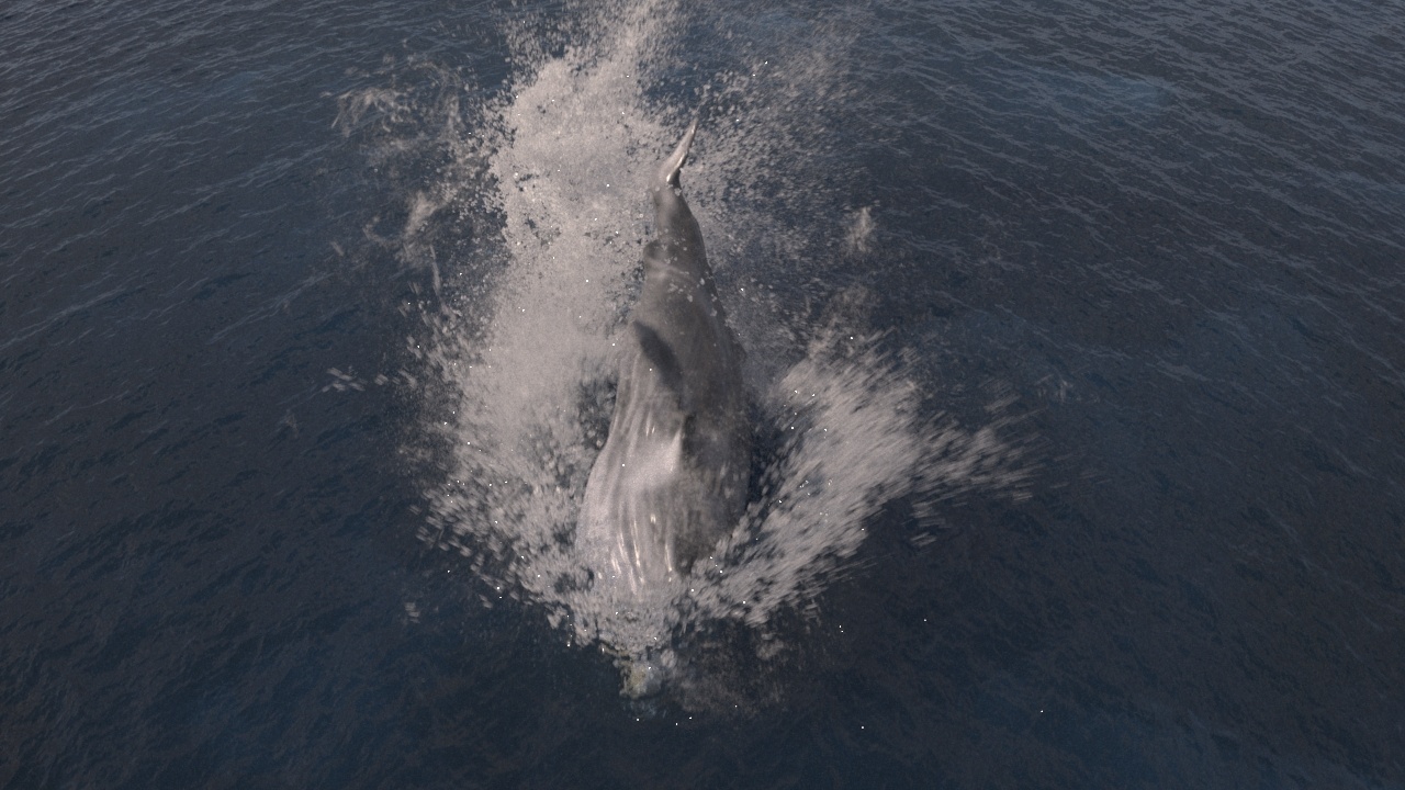
The instructions provided on this page guide you through the process of using Phoenix to create a splashy water simulation, caused by a humpback whale breaching the water and diving back into the ocean.
We create a section of ocean mesh, allowing the camera to capture the entire process of the whale jump. You'll see the splash when the whale surfaces and the thick foam when it dives deep. In addition, a top camera enables you to witness the impactful splash created by this giant creature.
The Download button below provides you with an archive containing the scene files.
Units Setup
Scale is crucial for the behavior of any simulation. The real-world size of the Simulator in units is important for the simulation dynamics.
Large-scale simulations appear to move slower, while mid-to-small scale simulations have lots of vigorous movements.
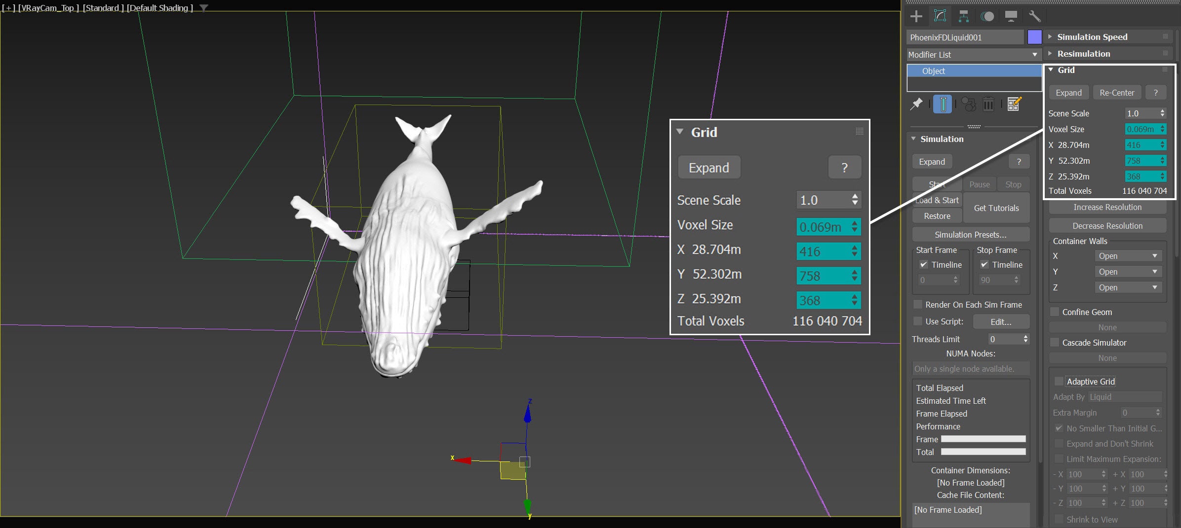
When you create your Simulator, check the Grid rollout where the real-world sizes of the Simulator are shown. If the size of the Simulator in the scene cannot be changed, you can trick the solver into working as if the scale is larger or smaller by changing the Scene Scale option in the Grid rollout.
The Phoenix solver is not affected by how you choose to view the Display Unit Scale — it is just a matter of convenience. Setting the units to Meters is a reasonable choice for this setup.
Go to Customize → Units Setup and set Display Unit Scale to Metric Meters. Also, set the System Units so that 1 Unit equals 1 Meter.

Scene Layout
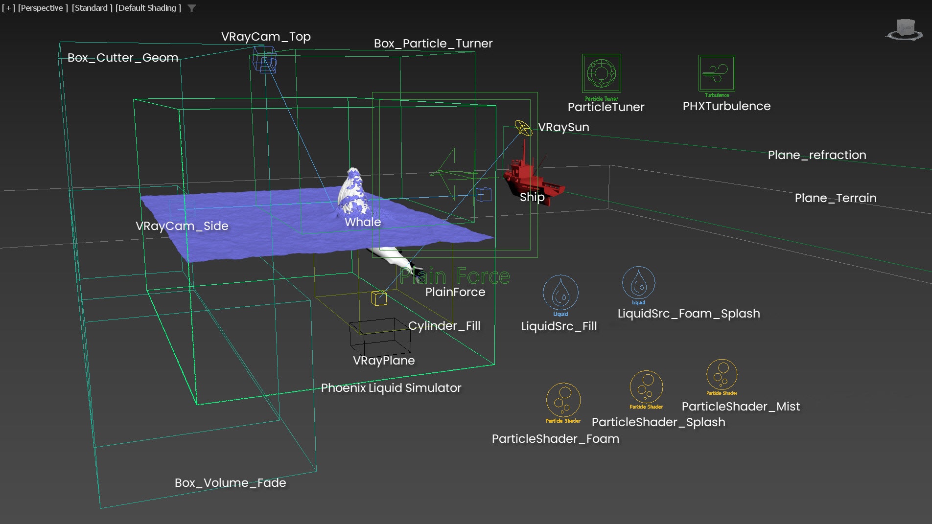
Here's a viewport screenshot of the final scene layout. It consists of the following elements:
- Phoenix Liquid Simulator;
- 16.5 meters long whale mesh, which is skinned, rigged and animated;
- LiquidSrc_Fill - Phoenix Liquid Source emitting liquid from Cylinder_Fill;
- LiquidSrc_Foam_Splash - Phoenix Liquid Source emitting Foam and Splash particles from the whale;
- Three Particle Shaders for the Foam, Splash and Mist particles respectively;
- PHXTurbulence - force to disturb the Mist and Foam particles;
- Particle Tuner - used to remove excessive liquid, when the whale is breaching out the surface of the water;
- Box_Particle_Tunner - helper geometry that covers the volume when the whale breaches out, it works together with the Particle Tuner;
- Cylinder_Fill - geometry that is used as a liquid source for the LiquidSrc_Fill;
- Phoenix Plain Force - wind force blowing the Splashes, Mist and Foam;
- Box_Cutter_Geom - helper geometry for the Cutter Geom in the Rendering rollout of the Simulator, used for creating a section for the under - above water transition;
- Box_Volume_Fade - helper geometry for fading the effect of the VRayDisplacement over the ocean mesh in order to get a cleaner and smoother mesh for the section;
- VRayPlane - used as an infinite ground surface for the sideview camera. It helps blocking the light from the seabed and helps to get the deep water shading effect;
- Plane_Terrain - geometry used for the underwater terrain for the top view camera. The terrain enhances the ocean's visual appeal.
- V-Ray Sun & Sky - for lighting. The V-Ray Sun/Sky also provides a cloudy sky to make the shot more interesting;
- VRayCam_Top for the top view;
- VRayCam_Side for the side view.
Whale Geometry, Material and Animation
Here, we provide a whale geometry that is a solid, single-mesh, and watertight. The model has undergone an STL Check Modifier, which confirms that there are no errors. The whale is skinned with a Skin modifier and has the animation keyframed, making it ready for fluid simulation.
The whale model is around 16.5 meters long, which matches the size of a real-world humpback whale.
To facilitate easy manipulation of the whale animation, the number of bones used in the rigging is minimized. You can set up a more advanced rig for your custom model depending on your requirements and preferences.
The Whale_bone_center is the root bone for all bones. If you want to move every bone in the whale, this is the bone for the task.
The cavities in the nostrils might cause the release of unwanted shooting particles when the whale surfaces. Therefore, we partially fill the holes. Take this into consideration when preparing your custom geometry.
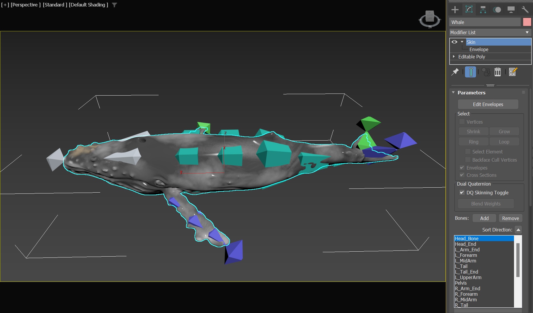
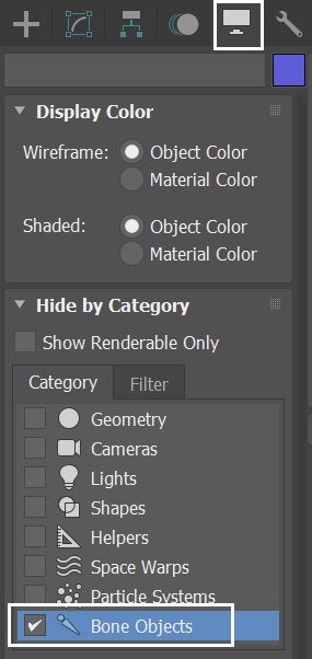
You can use the Display/Hide by Category - Bone Objects option to quickly hide/unhide the bones in the scene. By hiding the bones, they don't interact with Phoenix fluid by default.
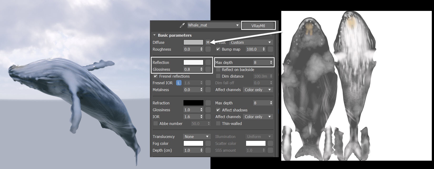
The whale model is properly unwrapped and has a basic V-Ray material applied. A texture map of the whale is assigned to the Diffuse slot.
The Reflection color is set to RGB color (237, 237, 237) to make the whale reflective.
The Reflection Glossiness is set to 0.8 to blur the reflections a bit.
The Max depth is set to 8 to improve the reflections.
This is the preview of the whale jump animation for VRayCam_Side and VRayCam_Top.
We temporarily place a plane to show where the sea level is.
Scene Setup
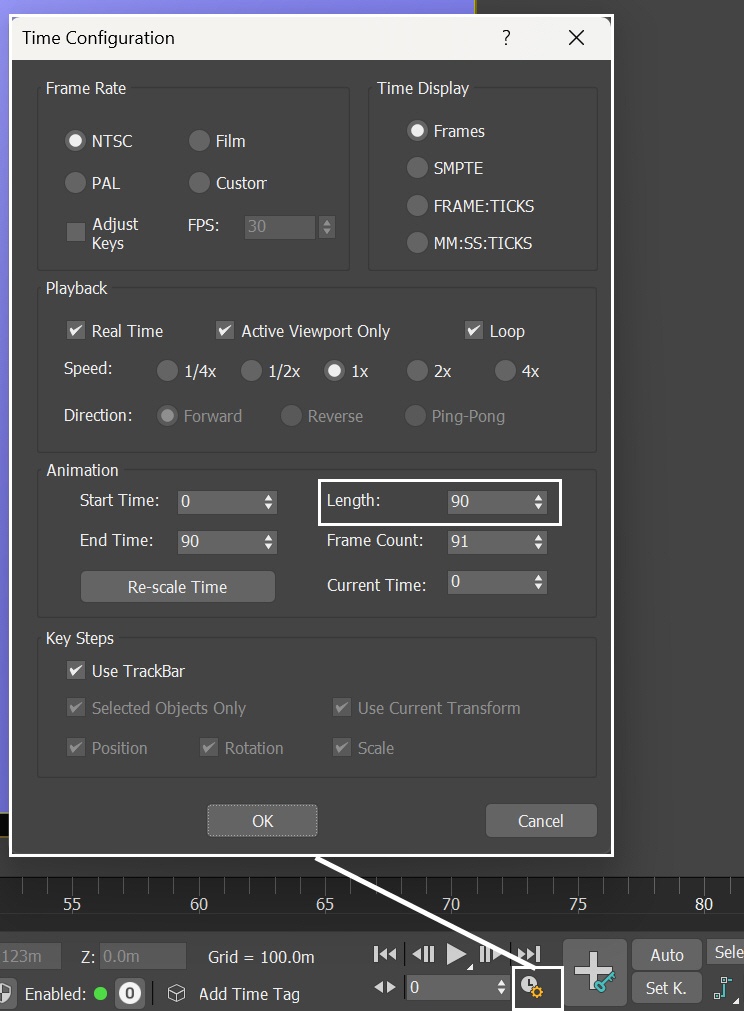
Set the Animation Length parameter appearing in the Time Configuration window to 90, so that the Time Slider goes from 0 to 90.
The animation length is 90 frames, but we render two sequences with the two separate cameras, so it totals to 6 seconds of animation.
This tutorial consists of many steps to follow. To keep it concise, let's focus only on the Phoenix related steps and feel free to use the camera and light settings in the provided sample scene.
For your reference below, you can find the light and camera settings.
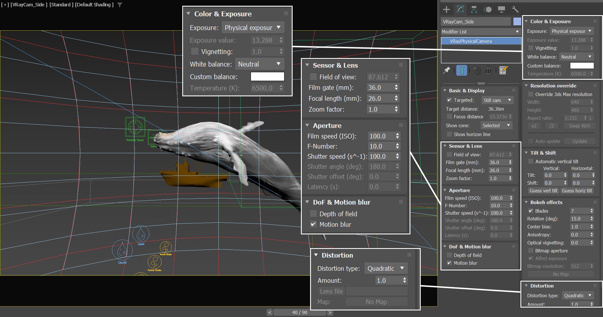
Camera Setting for VRayCam_Side
Add a VRayPhysicalCamera from Create Panel > Cameras > V-Ray. Rename the camera to VRayCam_Side. The exact position of the Camera is XYZ: [-17.9, 14.82, 2.2 ].
The exact position of the Camera Target is XYZ: [18.1, 12.14, 2.21].
From Aperture, the Film speed parameter is set to 100.0. F-Number is set to 10.0. Shutter Speed is set to 100.0.
In the Sensor & Lens rollout: Film gate is set to 36.0mm. Focal length is set to 26.0mm.
From Color & Exposure, set the White Balance option to Neutral.
Enable Motion blur.
Set the Distortion Amount to 1.0.
Ensure that the side view camera is positioned within the simulation grid in order to get a proper ocean mesh when using the Geometry Cutter option to create the ocean section.
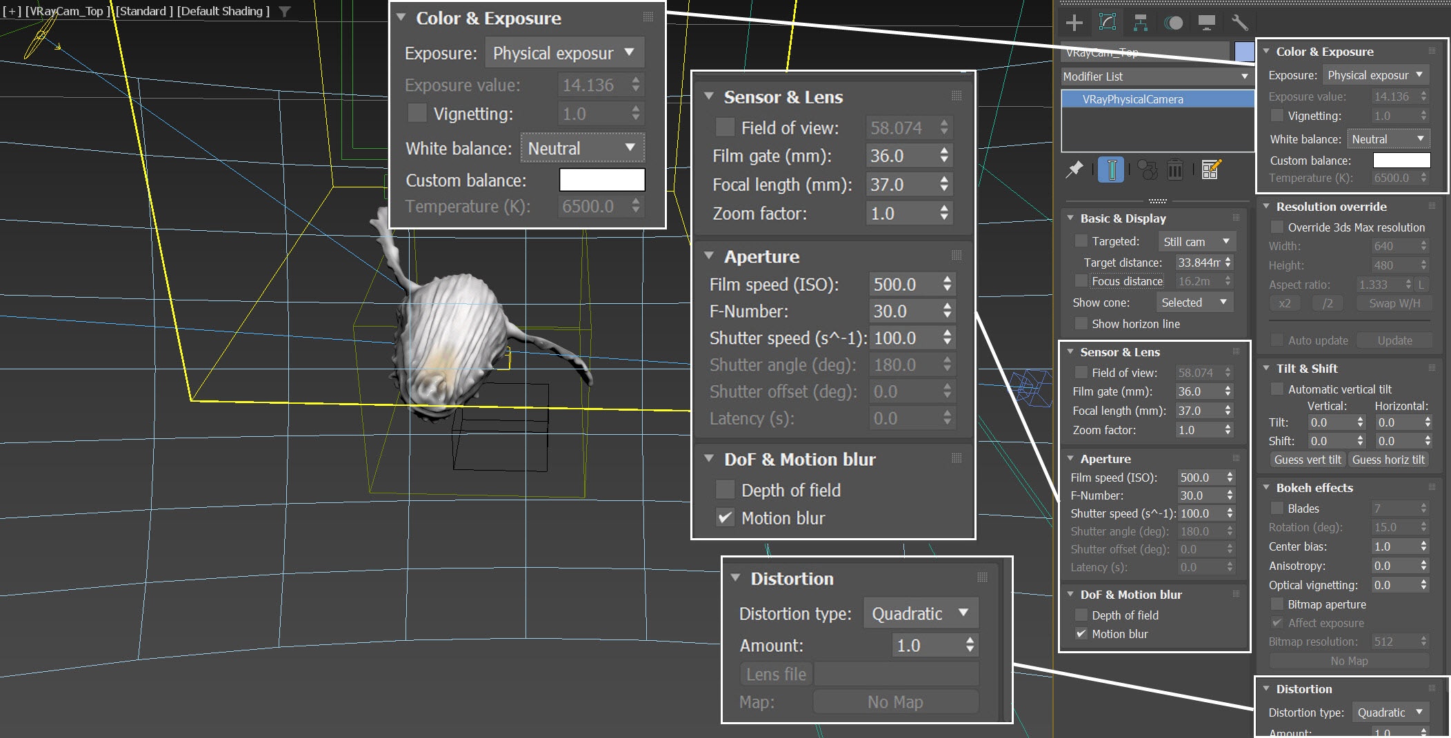
Camera Setting for VRayCam_Top
Create a VRayPhysicalCamera from Create Panel > Cameras > V-Ray. Rename the camera to VRayCam_Top. The exact initial position of the Camera is XYZ: [-2.85, 34.77, 26.0 ] at frame 0, then it is moved to XYZ: [-2.85, 55.57, 21.74 ] at frame 90.
From Aperture, the Film speed parameter is set to 500.0. F-Number is set to 30.0. Shutter Speed is set to 100.0.
In the Sensor & Lens rollout: Film gate is set to 36.0mm. Focal length is set to 37.0mm.
From Color & Exposure, set the White Balance option to Neutral.
Enable Motion blur.
Set the Distortion Amount to 1.0.
Take into account that the camera is in motion when determining the dimensions of the simulator. Make sure that the simulator is sized appropriately to encompass the camera's field of view for the entire animation, spanning from frame 0 to frame 90.
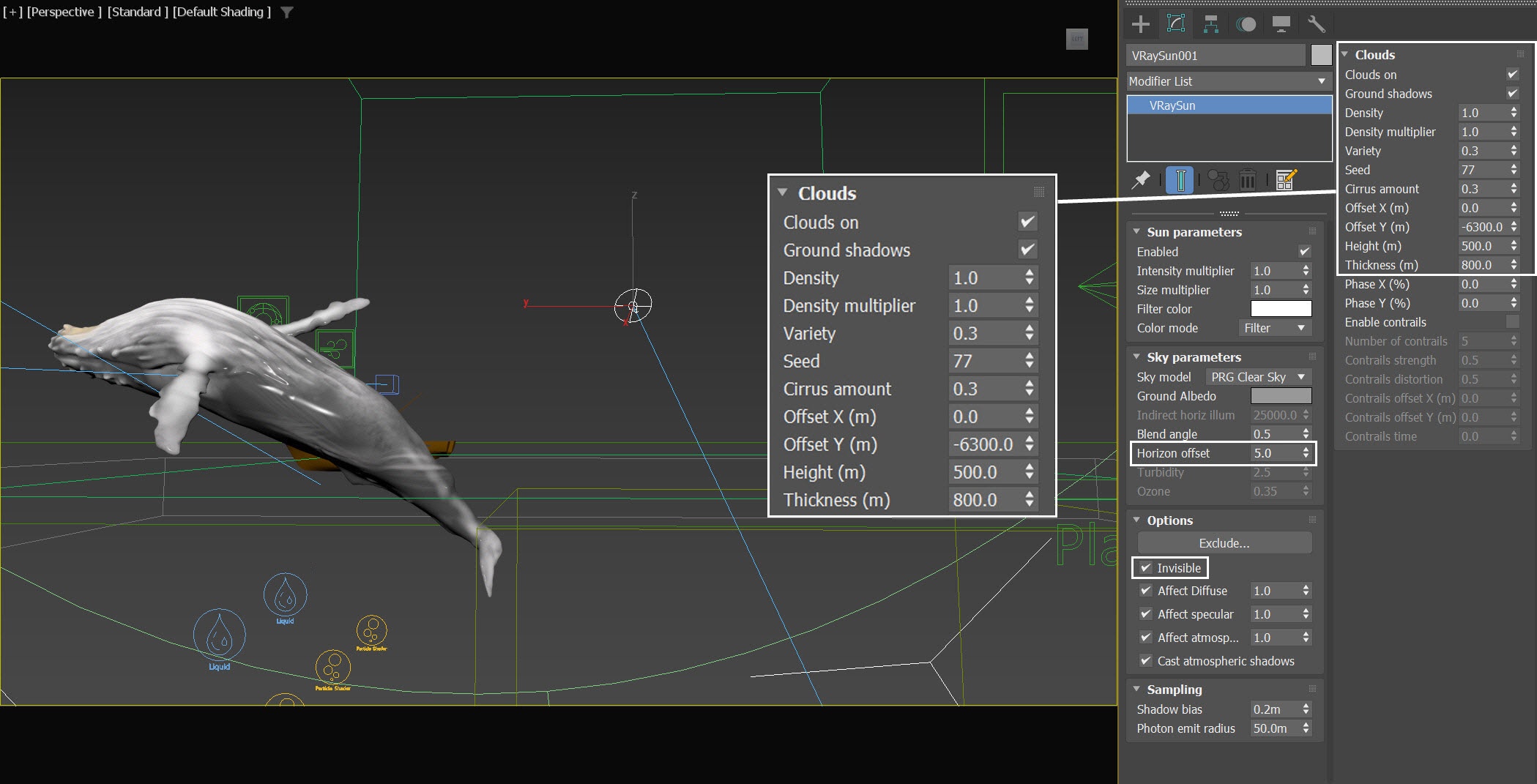
Lighting
From Create Panel → Lights → V-Ray → VRaySun, create a VRaySun in the scene.
The exact position of the VRaySun is XYZ: [ 18.63, 3.87, 16.95 ].
The exact position of the VRaySun Target is XYZ: [0.0, 0.0, 0.0 ].
In the Sky parameters rollout, set the Horizon offset to 5.0.
In the Options rollout, enable the Invisible option.
Enable the Clouds on option:
- Set Density to 1.0
- Set Seed to 77
- Cirrus amount to 0.3
- Offset Y(m) to -6300.0
- Height (m) to 500.0
- Thickness (m) to 800.0
We tweak the Seed and Offset options to ensure that the generated cloud patterns harmonize well with the other elements in the scene, such as the whale, ships and overall composition. Feel free to create your own custom cloud pattern based on your preferences.
We set the Horizon offset to 5.0 so that the grey line won't show on the horizon.
We make the Sun invisible to prevent fireflies in the water reflections.
Anatomy of the Whale Jump
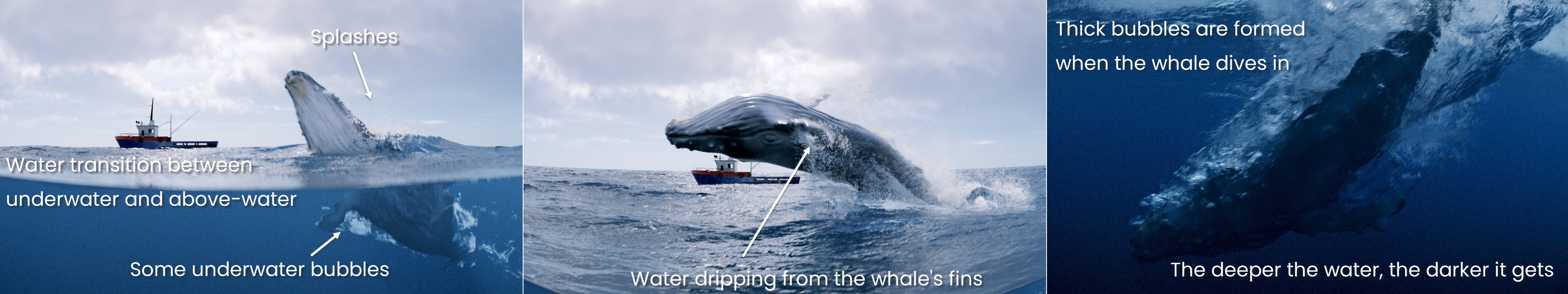
For the side view camera, let's create a section of the ocean mesh that allows us to observe the movements of the whale. We aim for a seamless transition between the underwater and above water shots.
When the creature surfaces, a small amount of splash and water drips from the whale's fins emerge. When the whale is diving in, it produces thick foam. As it dives deeper, the water progressively darkens. Additionally, we place a fishing boat in the far distance as a scale reference.
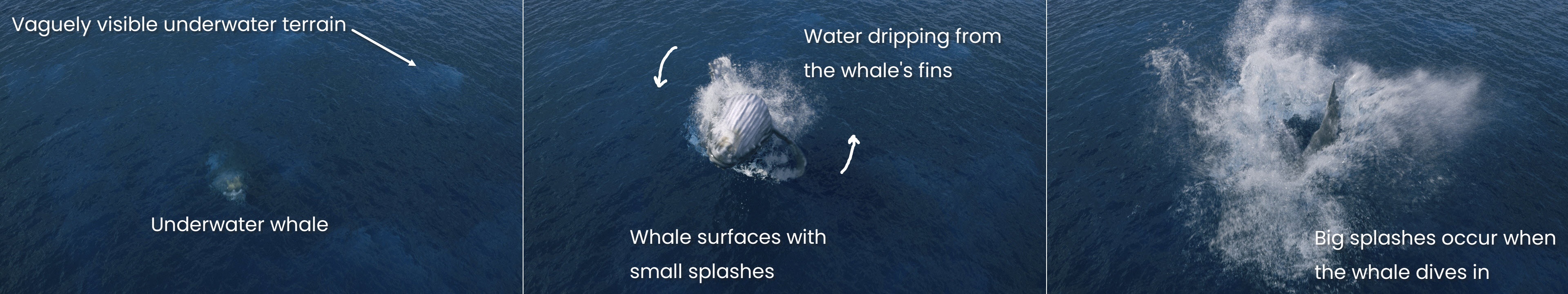
We introduce underwater terrain to the top view camera to prevent the ocean shading from appearing monotonous.
In comparison to the side view, the top view has no clouds in the sky and no ship for scale reference. We intentionally reduce the size of the ocean's texture in the displacement (through the Control by Wind Speed parameter) and animate the camera to enhance the shot. As the whale emerges, minimal splashes can be observed. The creature gracefully rotates its body, revealing water dripping from its fins. Subsequently, it plunges back into the water, creating big splashes upon impact.
Both cameras are equipped with wide-angle lenses and intentional distortion to accentuate the immense size of the magnificent creature.
Phoenix Liquid Simulation
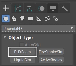
Open the Whale_jumps_start.max scene in the provided package and let's create a Liquid Simulator. Go to Create Panel > Create > Geometry > PhoenixFD > PhoenixFDLiquid.
The exact position of the Simulator in this example scene is XYZ: [0.0, 16.3, 5.5].
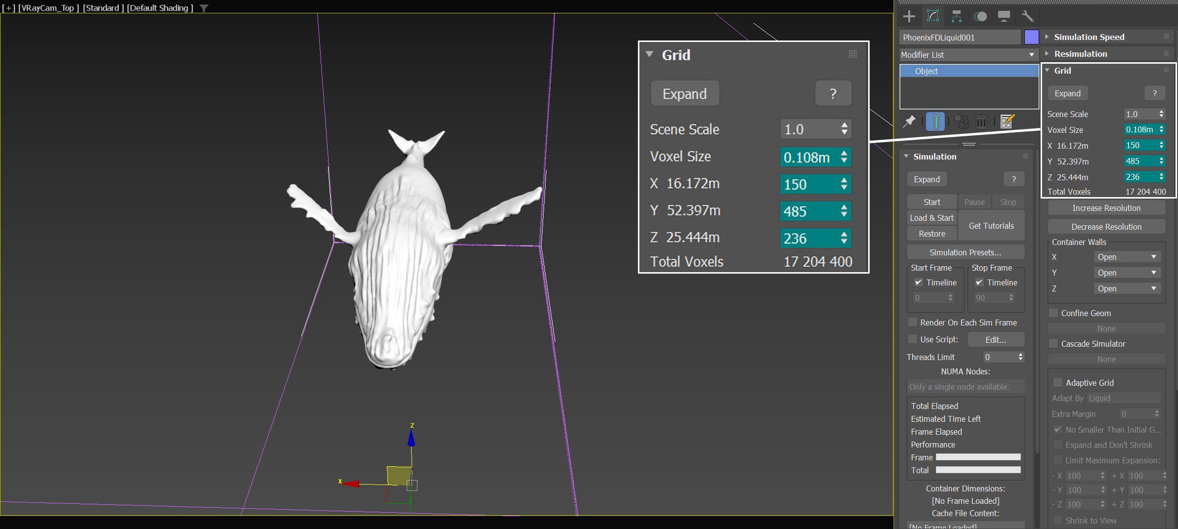
Open the Grid rollout and set the following values:
- Voxel Size: 0.108 m
- Size XYZ: [150, 485, 236]
- Container Walls: Open to X, Y and Z
During the R&D phase, we only cover a slightly larger region around the whale animation with the simulator for faster iterations.
Setups like this, where the simulation behaves similarly along the simulator's width, enable us to iterate over just a slice of the simulation grid and be confident that when we widen the simulator, the simulation maintains its characteristics and does not change drastically.
When configuring the position and dimensions of the simulator's grid, it is crucial to take into account the height of the splashes generated when the whale surfaces and dives. Neglecting this aspect may lead to the cropping of water splashes at the top.
Additionally, it is essential to consider how deep in the ocean the whale is, in order to ensure that the grid volume adequately encompasses it throughout the animation.
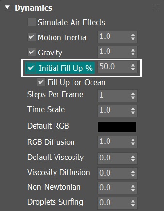
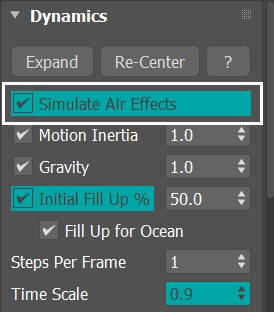
Select the Dynamics rollout of the PhoenixFDLiquid. Enable the Initial Fill Up %. Set the value to 50.0.
This way the simulator is filled with liquid at the start of the simulation.
Select the Output rollout of the PhoenixFDLiquid. Leave everything as default.
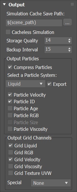
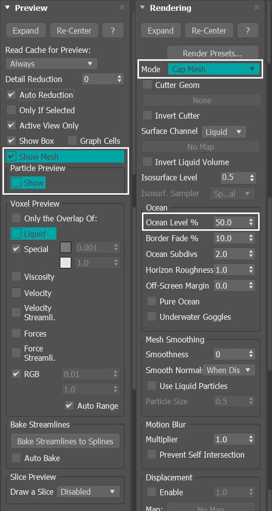
Select the Preview rollout of the PhoenixFDLiquid simulator. Enable the Show Mesh option. Disable the Particle Preview option.
As for the Rendering rollout, switch the Mode to Cap Mesh. Set the Ocean Level % to 50.0.
This way only the top part of the liquid surface is shown and it allows an easier iteration.
The value of 50.0 for Ocean Level % in the Rendering rollout corresponds to the value we just set in the Simulator's Dynamics Initial Fill Up%.
Initial Simulation
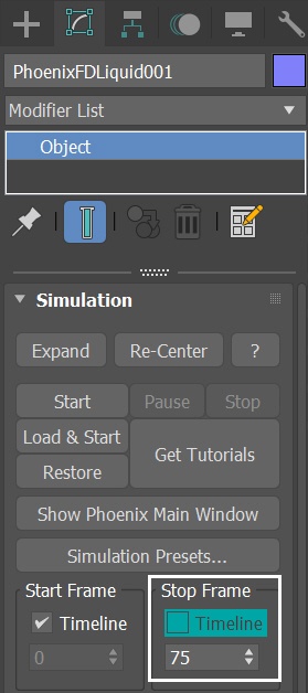
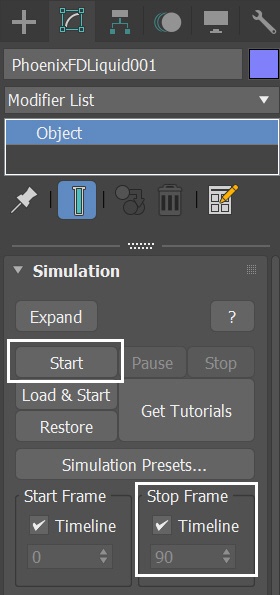
Select the Simulation rollout of the Phoenix Liquid Simulator. You don't have to simulate the full length of the animation. Only a sample is enough, so set Stop Frame to 75.
Press the Start button to simulate.
Here's a preview animation of the simulation up to this point.
As the whale surfaces swiftly from the water, it creates a large air pocket that rises and bursts like a big bubble. Unfortunately, this result does not align with an actual footage of a whale breaching.
Although we can alleviate the issue of air pockets to some degree by increasing the Steps per Frame (SPF) in the simulator, it results in longer simulation times. Moreover, higher SPF tends to smooth out important details in the liquid. So in the following steps, let's create a liquid source underwater that fills the air space generated by the whale surfacing.
Create a Cylinder
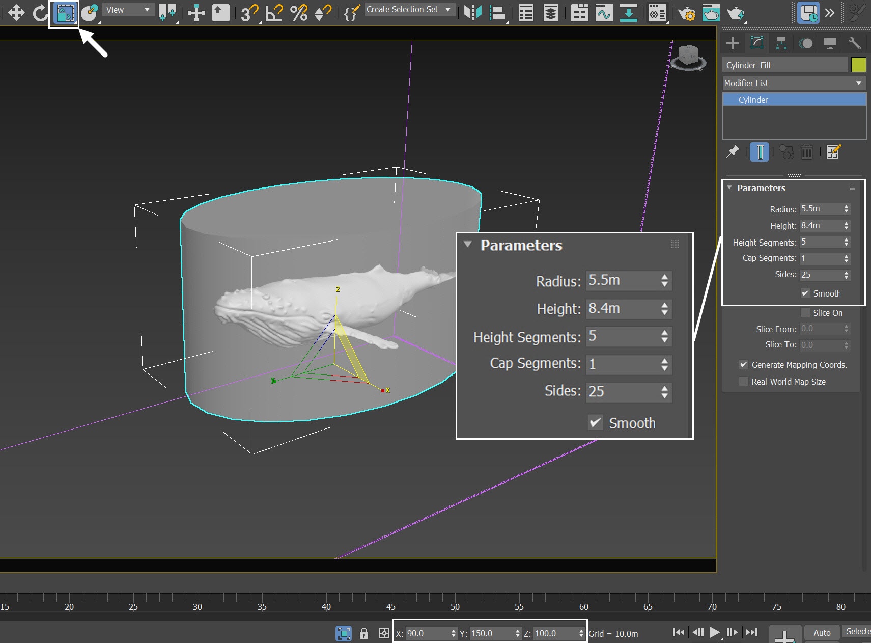
Go to Create Panel → Geometry → Standard Primitives → Cylinder. Create a cylinder in the scene. Rename the cylinder to Cylinder_Fill.
Set its Radius and Height to 5.5m, and 8.4m respectively. Height Segments to 5. Cap Segment to 1.
The exact position of Cylinder_Fill is XYZ: [0.54, 1.45, -1.85 ].
Use the Select and Non-uniform Scale tool to non-uniformly scale the whale, ensuring that the geometry volume fits better with it. The exact scaling is XYZ: [90.0, 150.0, 100.0 ].
The cylinder is just big enough to cover the underwater whale within a specific timeframe, allowing us to use it as a source emitter for liquid to fill the air pocket left behind.
When determining the position of the cylinder, we move it upwards from being submerged in the sea, approaching the sea level. However, be cautious not to raise it too high, as the liquid emitted from the cylinder may cause splashes or foam to form on the water surface, resulting in undesired circular patterns that are visible from the top-view camera.
We temporarily set the Display properties of the cylinder to See-Through, allowing for better visibility of how it encompasses the whale.
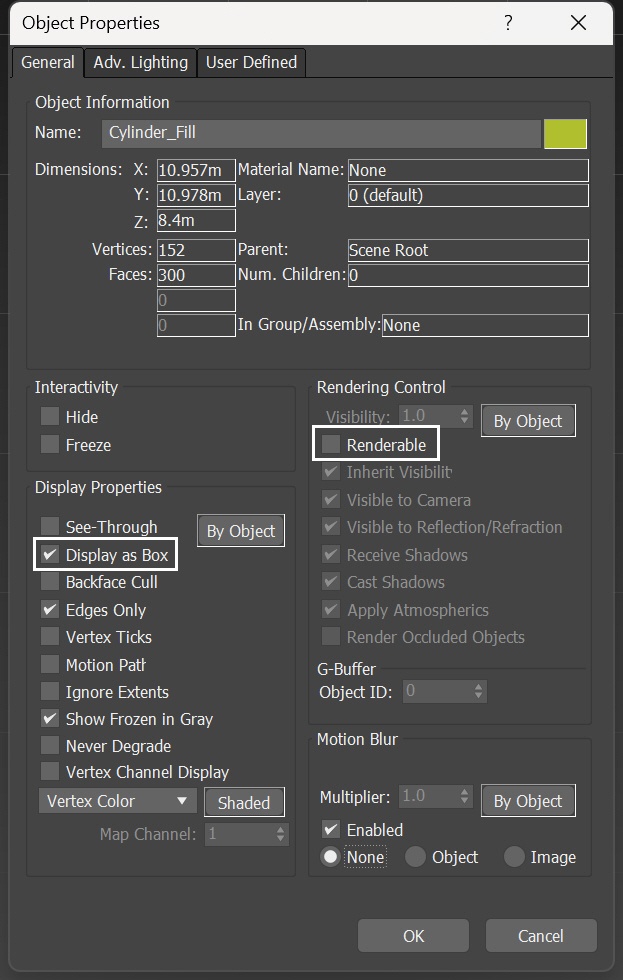
Since the Cylinder_Fill only serves as an emitter for the liquid source, there is no need to render the geometry. To achieve this, select the Cylinder_Fill, right-click, and choose Object Properties. Enable the Display as Box option and disable the Renderable checkbox.
Add Liquid Source
Add a Liquid Source from Helpers → Phoenix FD → Liquid Source. Rename it to LiquidSrc_Fill.
The Liquid Source is a Phoenix helper node. It determines which objects in the scene the Simulator emits from, how strong the emission is, etc.
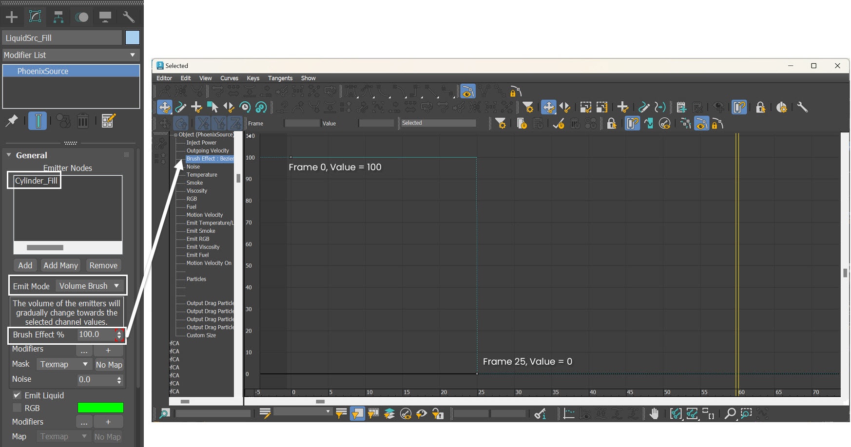
Add the Cylinder_Fill geometry to the Emitter Nodes list.

Once the emitter is added, switch the Emit Mode to Volume Brush. Animate the value for Brush Effect%. Set the value to 100 at frame 0, and change it to 0 at frame 25. Set all keyframes' tangents to Stepped.
This way, the Cylinder_Fill continuously fills the volume with liquid until it reaches frame 25.
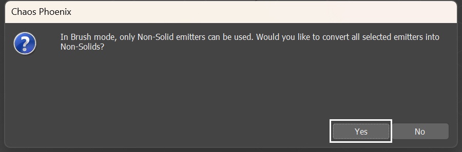
When switching to Brush mode, Phoenix prompts this window, asking you to convert the Cylinder_Fill to Non-Solid. Confirm.
When the emitter is Non-Solid it will just emit liquid, but its surface won't interact with the fluid.
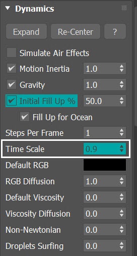
With the simulator selected, in the Dynamics rollout, decrease Time Scale to 0.9. This slows down the liquid a bit for aesthetics purposes.
With those new settings, let's run the simulation again.
Here's the new preview animation.
Notice how the LiquidSrc_Fill effectively seals most of the air pockets around the whale underwater, but the whale still generates excessive water splashes as it surfaces.
Adjust Motion Velocity Effect
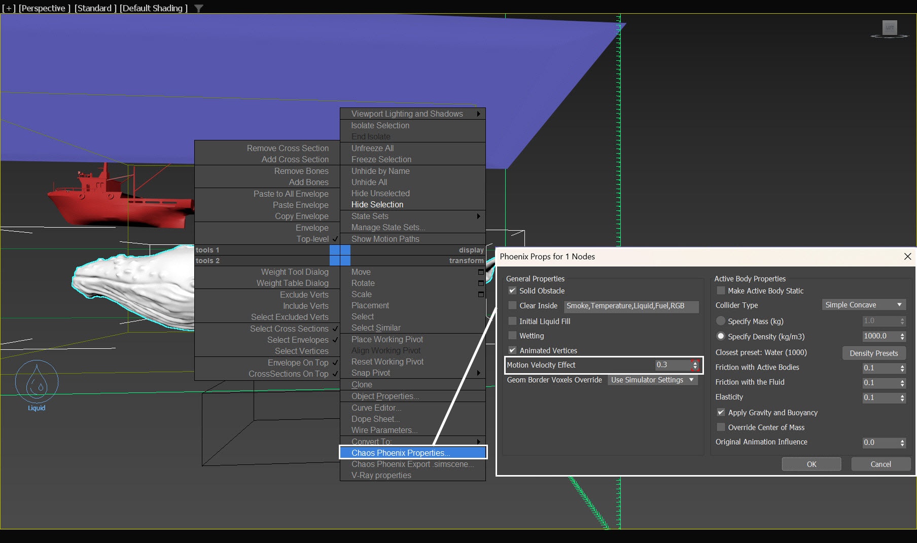
To minimize the water splashes when the whale surfaces, while maintaining impactful water splashes when it dives back in, let's animate the Motion Velocity Effect of the whale.
Right-click on the selected whale and choose the Chaos Phoenix Properties option.
Motion Velocity Effect allows you to control the impact of a moving object over the fluid. The motion could be caused by translation, rotation, scaling of the object, or by vertex animation where the vertices should push the fluid with their vertex velocities. The higher the value is, the stronger the fluid reaction to the body's motion is.
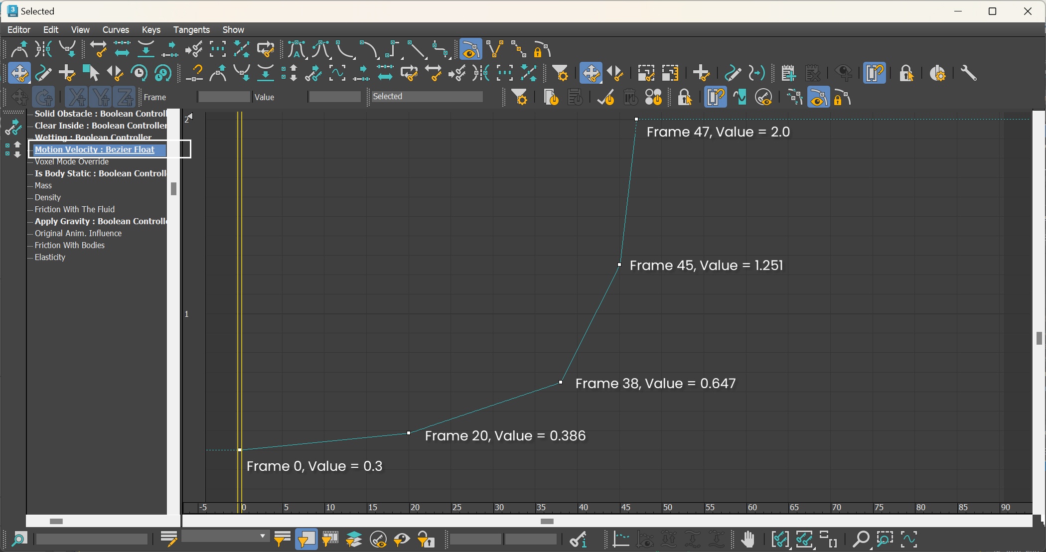
Now, let's go to Graph Editors/Track View → Curve Editor and set keys to the curve of Whale's Motion Velocity Effect. Set keyframes to the parameter, so it can change over time.
Each frame and value are shown in the screenshots. Set all tangents to Linear.
In the last keyframe, we assign a value of 2 to the Motion Velocity Effect, which is twice the strength of the default value, in order to enhance the impact of the splashes. Feel free to modify this curve according to your preference.
Here's another preview of the simulation.
Now the splashes are significantly reduced, but some residual water splashes can still be observed when the whale breaches the surface.
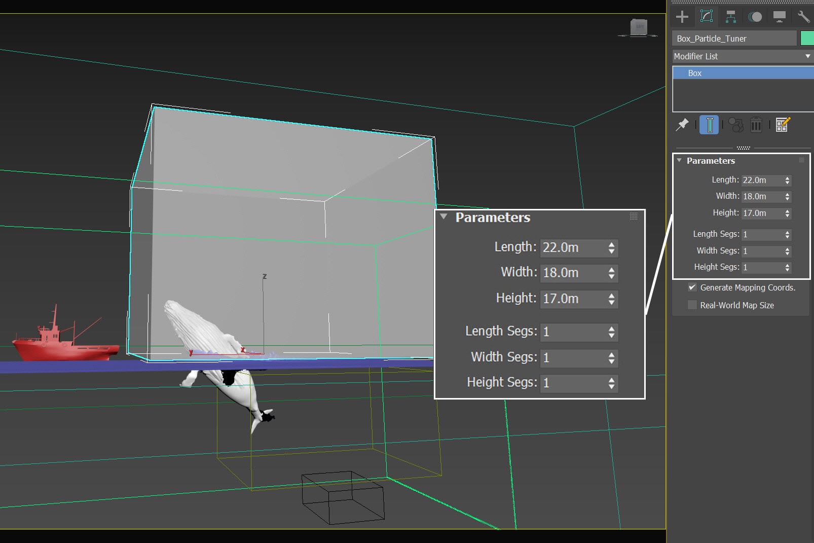
Create a Box for Particle Tuner
Go to Create Panel → Geometry → Standard Primitives → Box . Create a box in the scene. Rename the box to Box_Particle_Tuner.
Set its Length, Width and Height to 22.0 m, and 18.0m and 17.0m respectively. Segs from all sides to 1.
The exact position of Box_Particle_Tuner is XYZ: [0.0, 6.9, 8.0 ]. The box is just big enough to cover the water splashes when the whale surfaces.
We temporarily set the Display properties of the Box_Particle_Tuner to See-Through, which provides better visibility of the area where upward water splashes are affected.
Since the Box_Particle_Tuner is solely used to define the region where the Particle Tuner affects the liquid, there is no need to render the geometry.
Right-click on the selected Box_Particle_Tuner and choose Object Properties. Enable the Display as Box option and disable the Renderable checkbox.
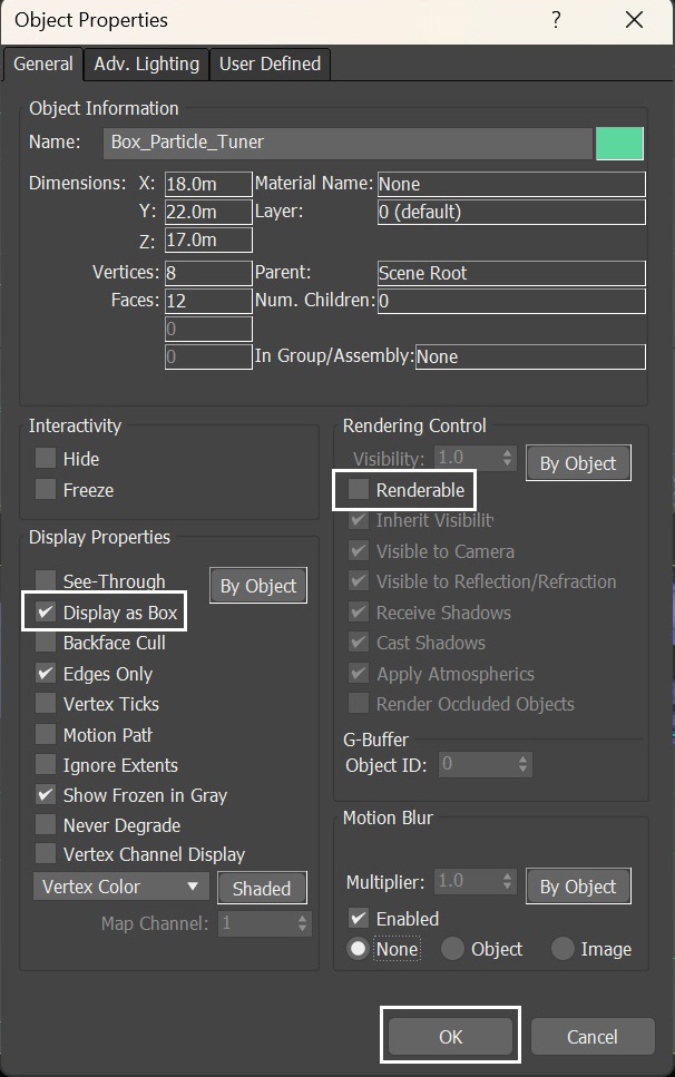
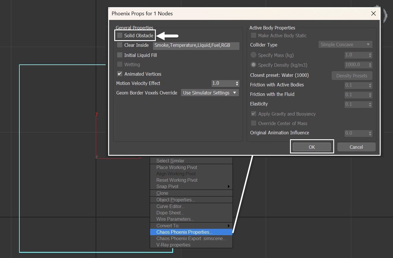
With the Box_Particle_Tuner selected, right-click and choose Chaos Phoenix Properties. Disable the Solid Obstacle option, so that thе box doesn't collide with the fluid.
Set up the Particle Tuner
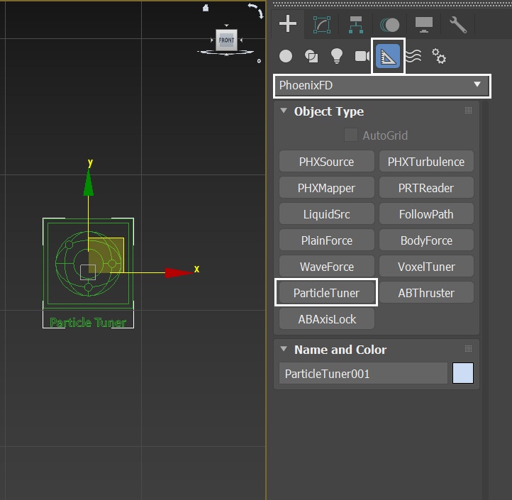
Go to Create Panel → Helpers → PhoenixFD → ParticleTuner. Create a Particle Tuner anywhere in the scene.
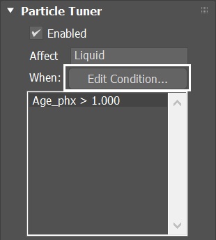
With the Particle Tuner selected, click on the Edit Condition button to change the condition.
The Particle Tuner assesses all particles in the simulation and changes their values, if they pass a certain condition.
In this example, we define the region using a box. Within the box, liquid particles are deleted within a specific time frame, with the assistance of the Particle Tuner.
The conditions can be straightforward, but you can also create more complex conditions using the Particle Tuner's Expression operators.
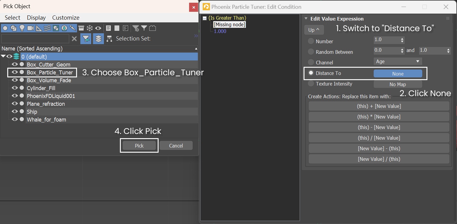
In the Edit Condition window, click on Age_phx, then the Edit Value Expression window shows up.
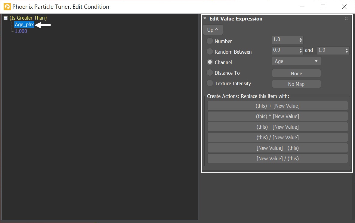
Switch the condition from Channel - Age to Distance To. Press the None button and choose the Box_ParticleTuner geometry in the scene.
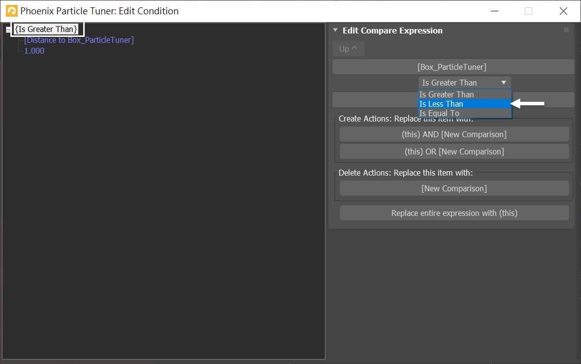
Click on the Is Greater Than, so the Edit Compare Expression window shows on the right. Change the condition from Is Greater Than to Is Less Than.
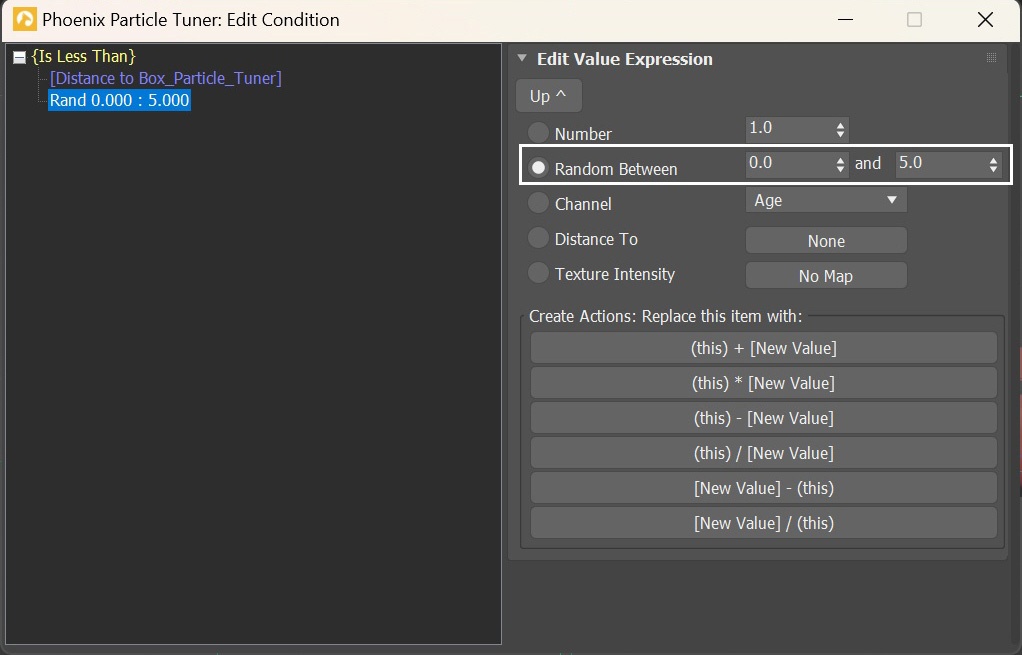
Below the Is Less Than option, change the option to Random Between.
Set the value to 0.0 and 5.0, which means that when the particles are within the range of 0 to 5 voxels from the Box_Particle_Tuner, they are affected and execute the behavior we define.
Note that the unit for distance is in simulation grid voxels. If you change the Simulator's Grid Resolution, it changes the actual distance to the particle affected by the Particle Tuner.
Instead of 0.0, we set a range of 0.0 to 5.0 for the distance condition to avoid abrupt changes near the edge of the Box_Particle_Tuner. Feel free to adjust the range as desired.
Now that we're done with the condition settings, close the Edit Condition window.
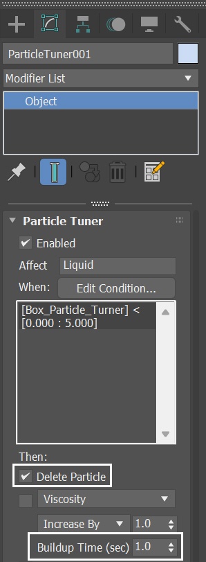
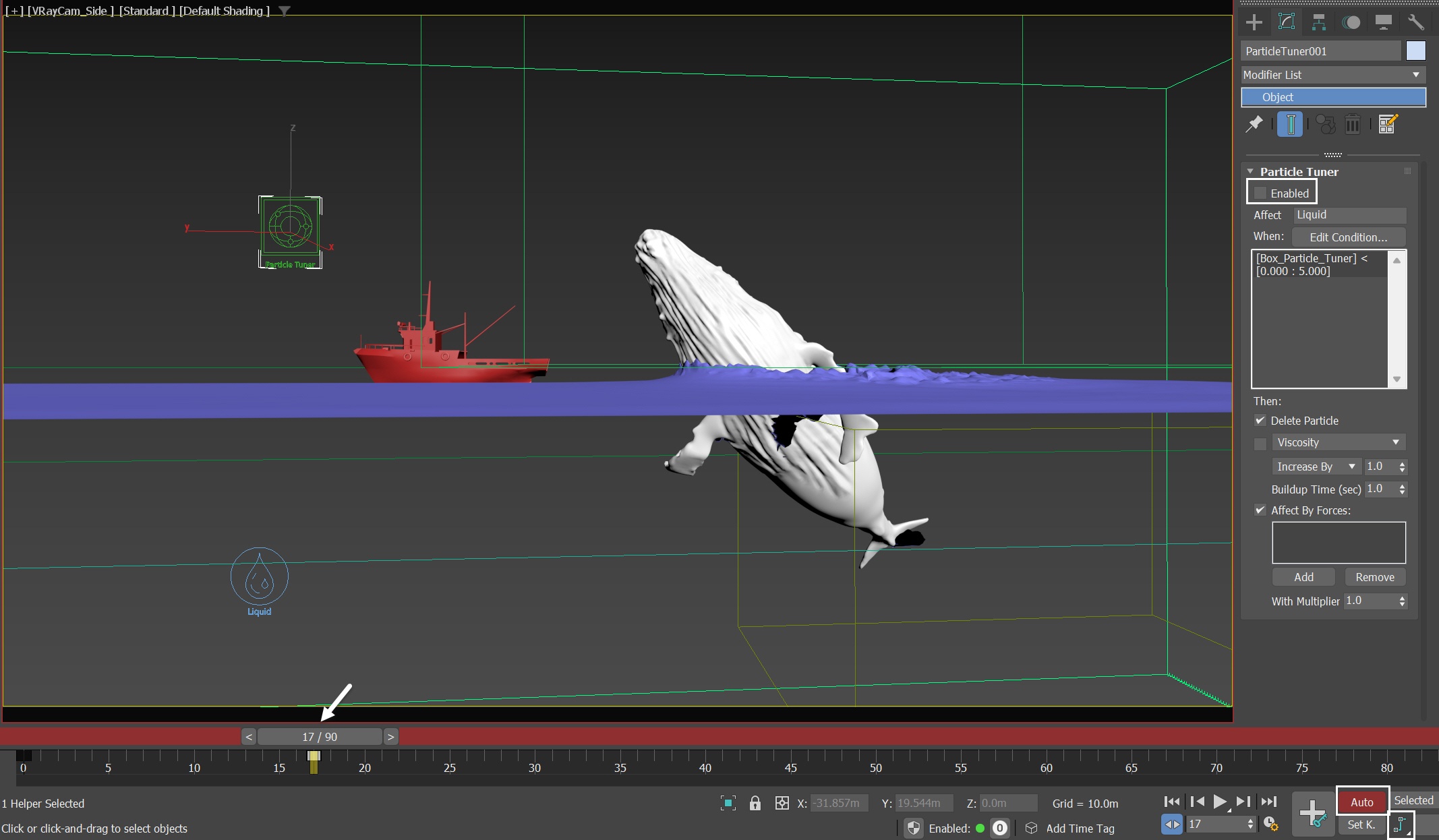
With the Particle Tuner selected, disable the Then - Viscosity checkbox and enable the Delete Particle option. Then, set the Buildup Time to 1.0 so that the Tuner doesn't act instantly. Make sure the Tuner only affects the Liquid particles.
With these new settings, run the simulation again.
This way, the condition set by the Particle Tuner is as follows: when particles enter the region of the Box_ParticleTuner, the Liquid particles are deleted within one second.
To restrict the Particle Tuner's effect to a specific time frame, let's animate its activation. Enable Auto Key and change the tangent type to Stepped. Now, at frame 0, enable the Particle Tuner. Move the time slider to frame 17, then disable the Particle Tuner by unchecking the Enabled option.
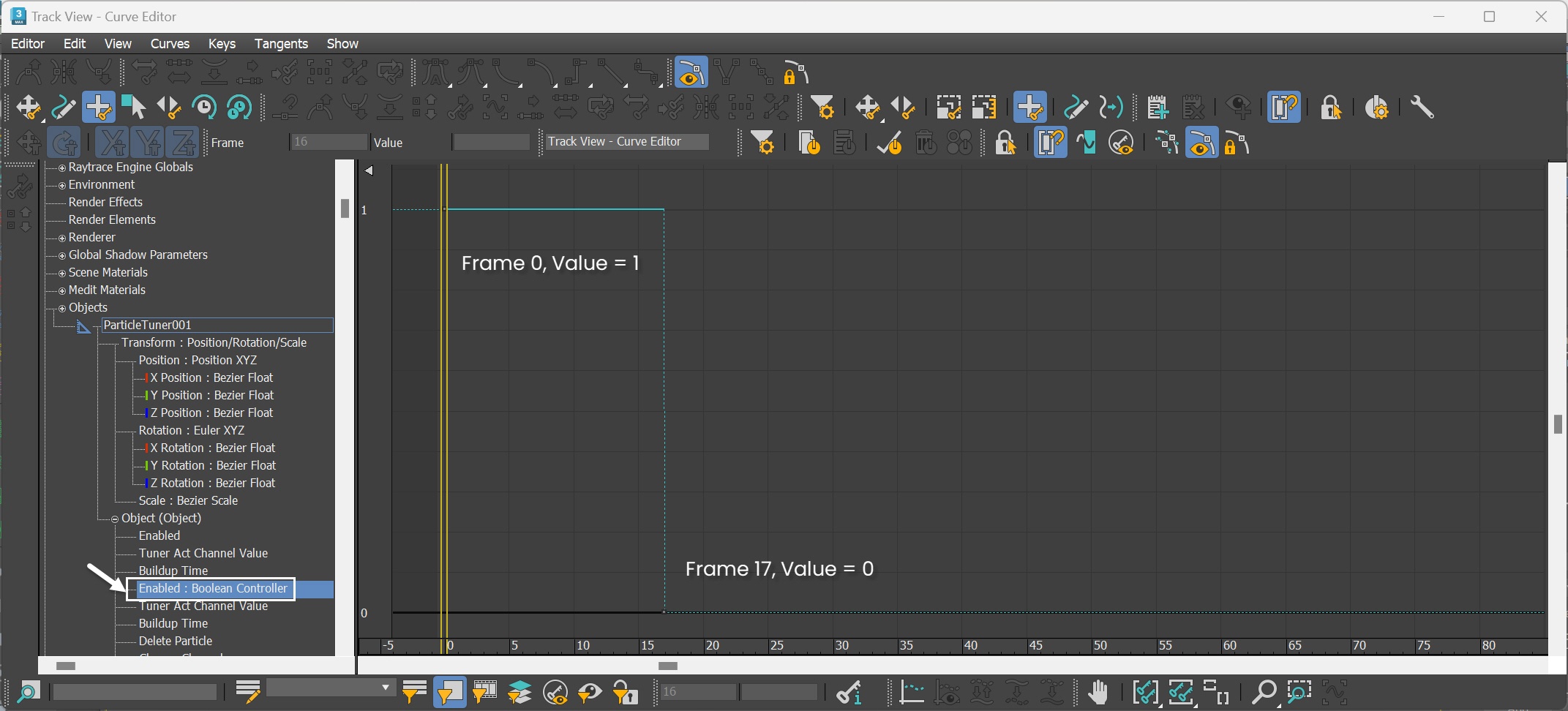
To verify if the animation is set correctly, navigate to Graph Editors/Track View → Curve Editor - Boolean Controller for the Particle Tuner.
The screenshots display each frame and its corresponding value, with all tangents set to Stepped.
Herе's the preview animation.
We successfully minimized the amount of water splashes when the whale surfaces, while still generating big splashes when it plunges.
With this solid foundation, let's now proceed to set up splash, mist, and foam particles for the scene.
Simulate Splash and Mist particles
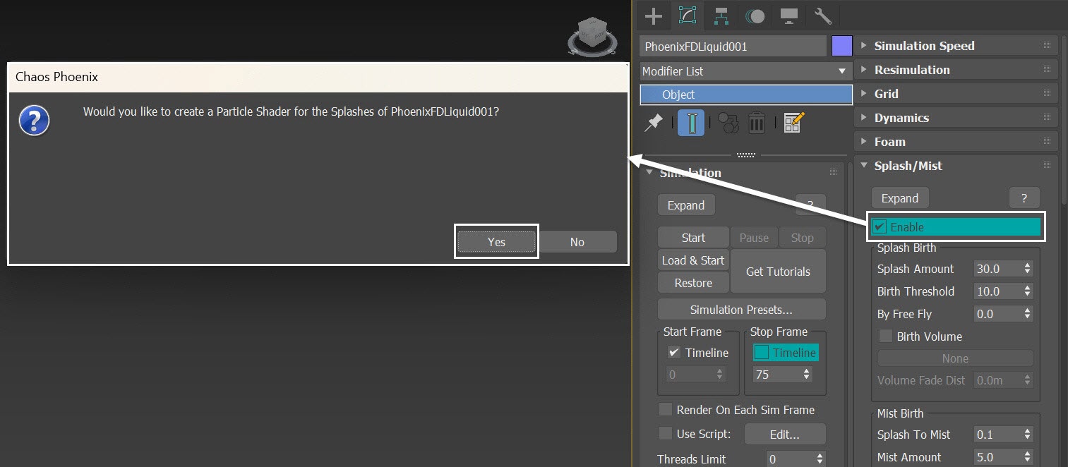
With the liquid simulator selected, go to the Splash/Mist rollout.
Enable the Splash/Mist option. When asked if you'd like a Phoenix Particle Shader generated for the Splash particles, select Yes. This automatically sets up the link between the Splash particles group, the Particle Shader, and the Liquid Simulator.
Rename the new Particle Shader to ParticleShader_Splash.
Run the simulation again.
Change Preview Color
With the simulator selected, in the Preview rollout, enable Particle Preview.
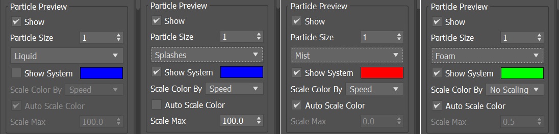
To easily spot which particles are which, let's change the color swatches for the different particle types.
Disable the Liquid particle preview by unchecking the Show System for the Liquid. Set the Splash, Mist, and Foam to Blue (RGB: 0, 0, 255), Red (RGB: 255, 0, 0), and Green (RGB: 0, 255, 0) color respectively.
The exact RGB color for the particle preview is not important - it's used only for the preview and not for rendering. Choosing other colors as long as they are distinguishable, is optional.
Here is a preview animation, where the emergence of splash particles are now seen.
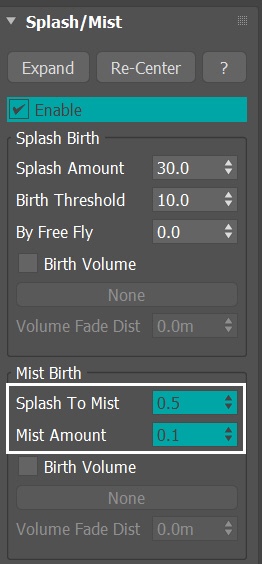
The current default setting for Splash to Mist is 0.1, which provides decent results. However, we would like to increase the value of the Splash to Mist parameter.
If we factor in the values of Splash Air Drag as 1 and Mist Air Drag as 2, increasing Splash to Mist also means changing the overall shape of the splash. For the purposes of this tutorial, we set the Splash to Mist value to 0.5. Additionally, we aim to minimize the quantity of Mist particles to enhance the rendering performance.
Check the FLIP Particles Life Cycle for more information on how liquid converts into splash and mist particles.
Splashes are the key visual component in the shot. We can have less Mist particles since they are more transparent in our final render and we can increase their size to compensate for that.
Monitor the Number of Mist Particles
Here is how to decide if the Mist particles are too many.
With the simulator selected, in the Simulation rollout you can find the Cache File Content window.
Based on the data, it is evident that the number of Mist particles is significantly higher than that of Splashes particles. Since the splashes are more crucial in this shot, let's decrease the number of mist particles, as they consume valuable simulation time.
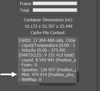
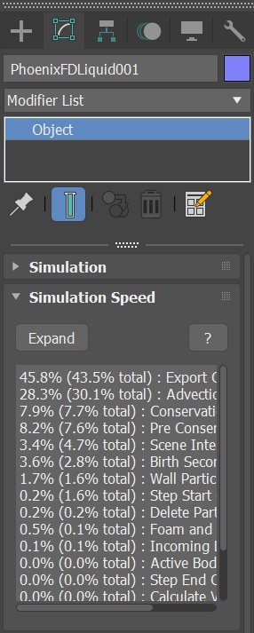
The Simulation Speed rollout in the Simulator provides you with valuable statistics on the duration of specific processes within the simulation. For each phase identified, advice is given on how to optimize it. This information offers insight into how you can optimize the simulation for better performance.
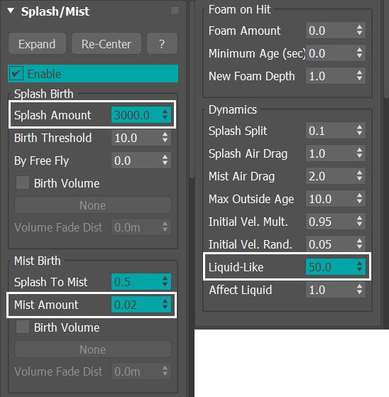
With the simulator selected, go to the Splash/Mist rollout. Under the Mist Birth section, increase the Splash To Mist parameter to 0.5. Reduce Mist Amount to 0.1.
Disturb Mist and Foam with Phoenix Turbulence
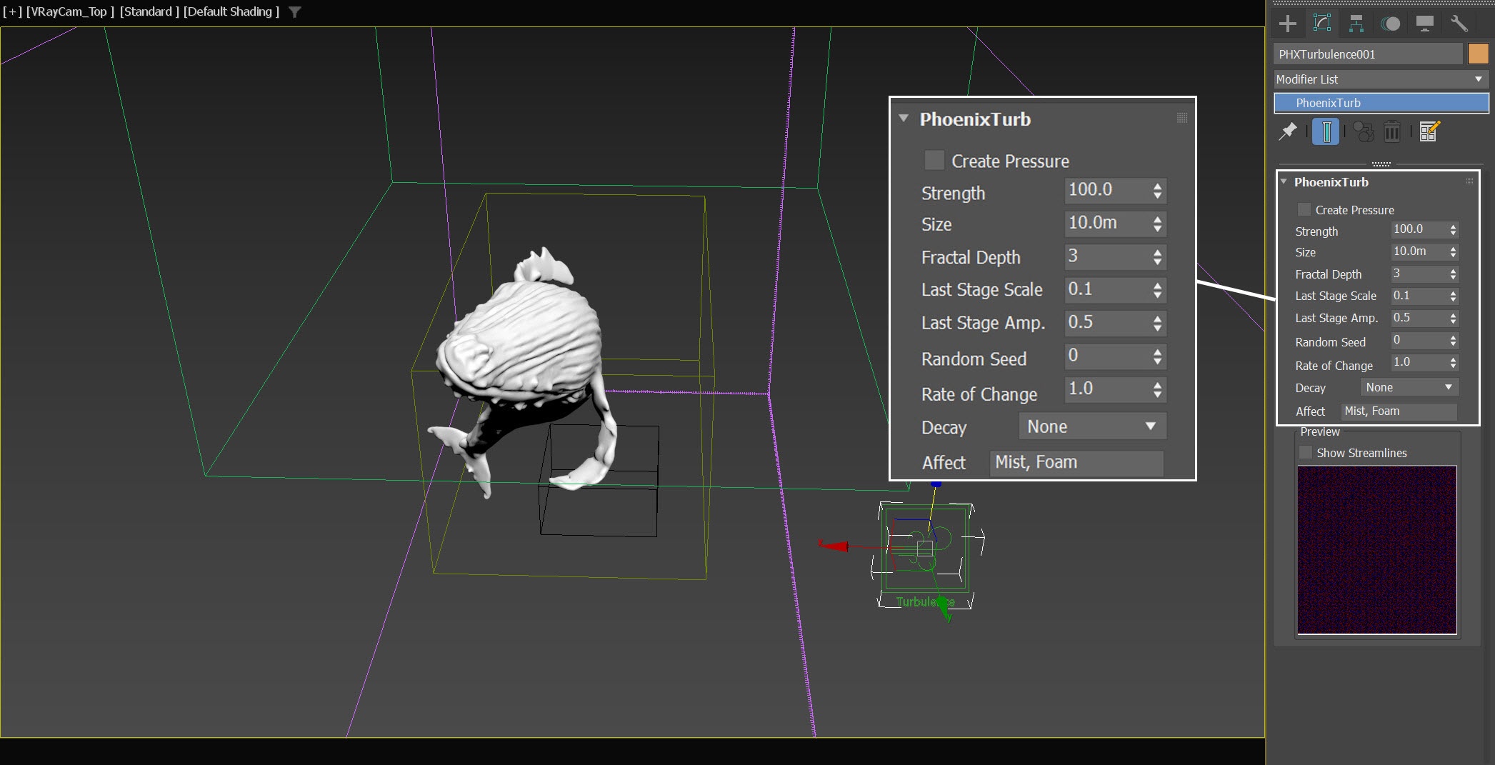
To create a Phoenix Turbulence, go to Create Panel → Helpers→ PhoenixFD and select PHXTurbulence.
Set its position to: XYZ[ 80.0, 50.0, 22.0]
Set its Strength to 100.0
Set its Size to 10.0m
In the Affect list, delete the other particles, and leave only Mist and Foam
Run the simulation again.
Here we add Mist and Foam to the Affect list, because we want to disturb only these two types of particles. Although Foam is not generated at this stage, let's add it to the Affect List in order to save the step of adding it later in the process.
Feel free to add other types of particles, too.
Here's the preview of the simulation up to this step.
Now a good Splash/Mist ratio is achieved, and the overall shape of the impact is satisfying.
Let's further improve the quality of the splashes. With the simulator selected, navigate to the Splash/Mist rollout. Increase the Splash Amount to 3000.0. However, keep in mind that this also results in an increased number of Mist particles. Therefore, we need to decrease the Mist Amount to 0.02 accordingly.
To enhance the blending of the splashes with the liquid mass, go to the Dynamics section and increase the Liquid-Like value to 50.0.
Run the simulation again.
Liquid-Like controls the splash particles' ability to stick to each other, forming different strings and tentacles. It makes the splash behave more like liquid and blends better with the behavior of the liquid mass. The higher this value, the larger the acceleration needed to break the connection. Note that larger values increase the calculation time. You can see the comparison images for the effect of the Liquid-like parameter here.
Here's a preview.
Simulate Air Effects
With the simulator selected, go to the Dynamics rollout. Enable the Simulate Air Effects option.
Run the simulation again.
Simulate Air Effects is an option that turns on the built-in air simulator for the areas in the simulation grid, which are not full of liquid. The air velocity is affected by the liquid movement, by Sources, or by fast-moving obstacles inside the Simulator. In turn, the air velocity affects and carries splash, mist and foam particles. The air simulation can dramatically increase the quality of splash and mist effects.
Here's a quick preview of the simulation.
Add Liquid Source for Emitting Splash from the Whale
To make the shot more interesting, let's incorporate a liquid source for the water dripping off from the whale.
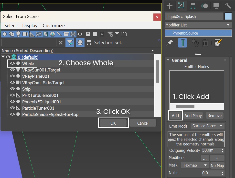
Add a Liquid Source by navigating to Helpers → Phoenix FD → Liquid Source. Rename it to LiquidSrc_Foam_Splash.
The Liquid Source is a Phoenix helper node that defines the objects from which the Simulator emits, along with the emission strength and other properties.
Include the Whale geometry in the Emitter Nodes list.
In this step, although we set the source to emit Splash particles, we rename the source to LiquidSrc_Foam_Splash. This is because, in a subsequent step, we'll activate the emission of foam particles from this source.
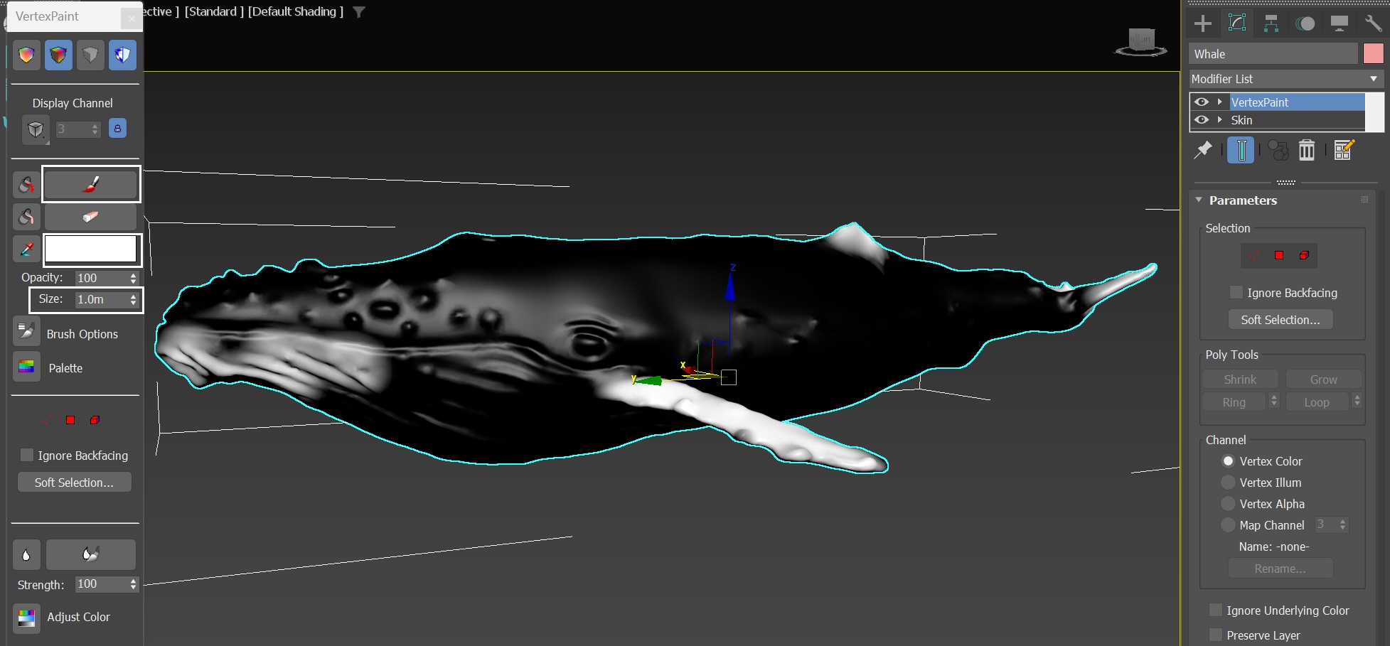
Instead of homogeneous emission, we want the splash to only emit from specific areas of the whale. Apply a VertexPaint modifier to the whale. In the VertexPaint toolbar, switch the shading mode to Vertex color display - shaded. This way, you can view the vertex color on the surface of the whale. Change the color swatch to black and fill the whale with black color using the bucket tool.
Since we're using a vertex color to mask the emission of particles from the whale, we set its base color to black. Black means no emission, while white shows the emission of splash particles.
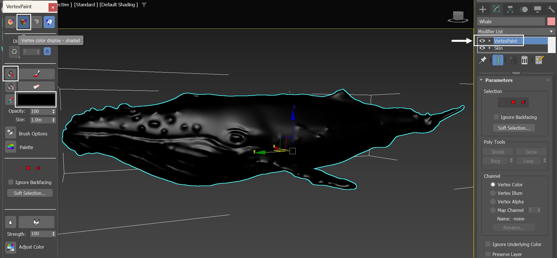
Now that the base color of the whale is set, we can paint the canvas white to define where the splash particles should be emitted from. Use the Paint tool, adjust the Size to 1.0m, and start painting with white color. For the purposes of this tutorial, we paint on the chin, fins, and tail of the whale.
The surface of the whale skin often hosts various symbiotic organisms, such as whale lice, barnacles, and algae. These organisms affect the surface properties of the skin, making certain areas more prone to absorbing water. Consequently, when whales breach the water surface, these areas are more likely to drip water or emit splash particles. You are welcome to paint the areas from which you want the whale to emit splash.
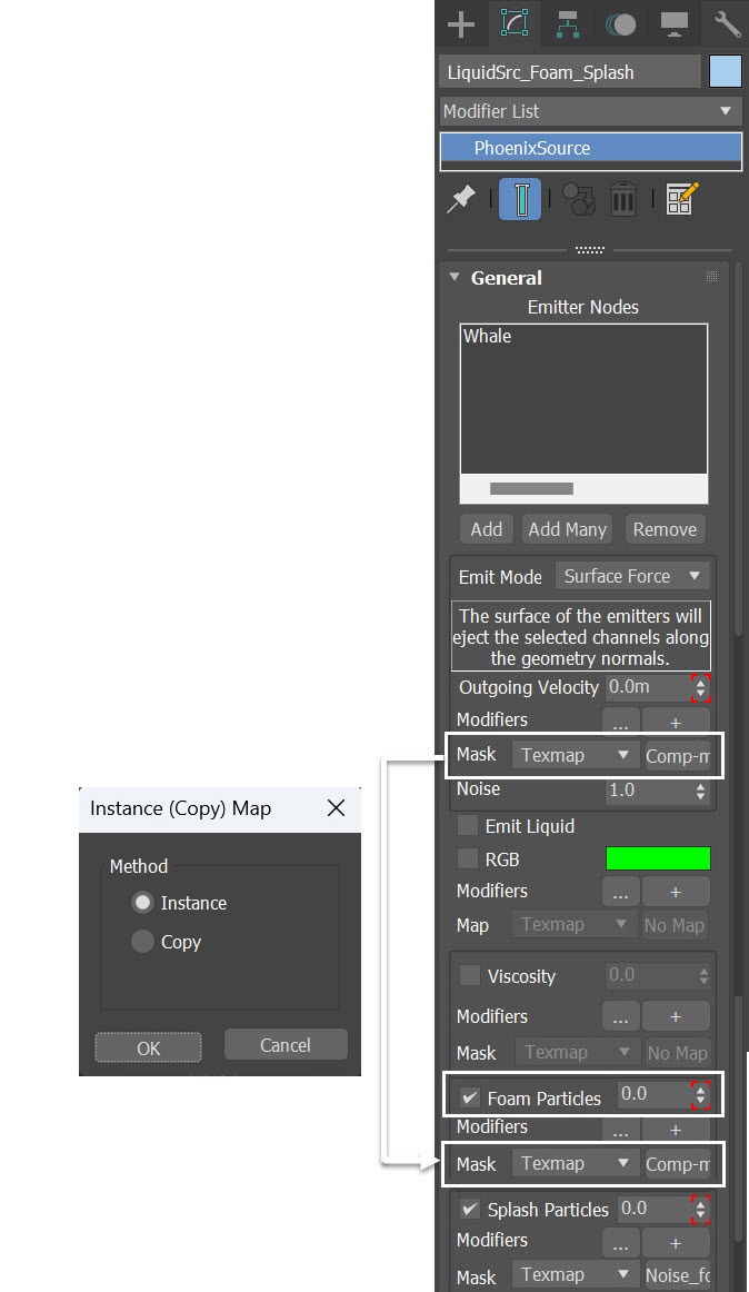
Once the emitter is added, animate the value for Outgoing Velocity and set the Emit Mode to Surface Force. This configuration ensures that the object emits particles solely from its surface area.
Disable the Emit liquid option to prevent the source from emitting liquid.
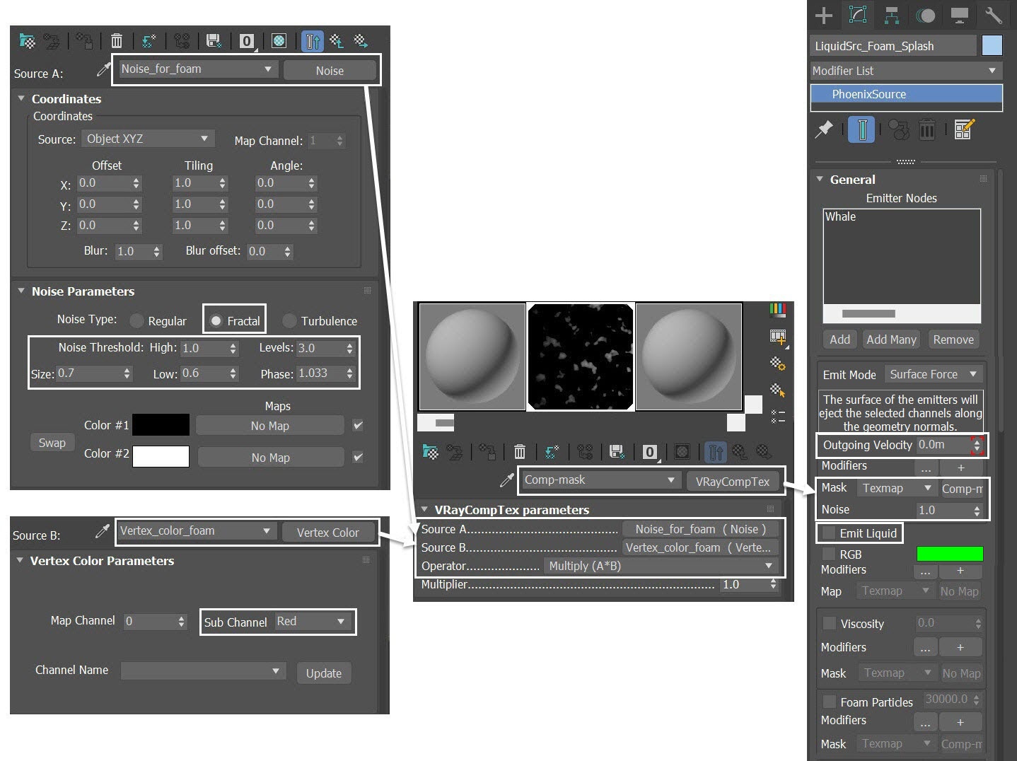
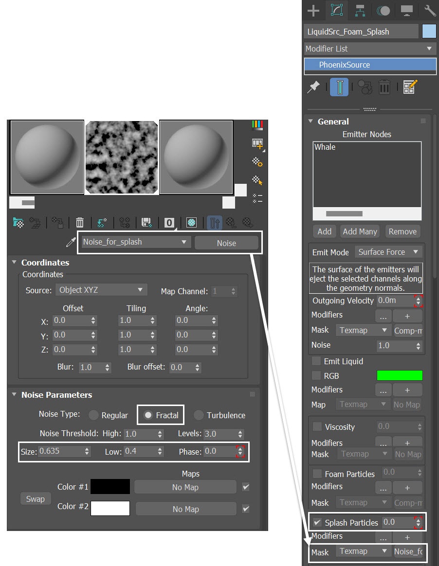
Instead of using Vertex Color as a direct mask, let's composite it with an animated Noise map. This way, we can have a mask for specific areas, not fixed in the same spot but changing over time. To achieve this, let's create a new VRayCompTex and rename it to Comp_mask. In the Source A slot, plug in a Noise map and rename it to Noise_for_foam. Set up the Noise_for_foam map as follows:
Change Noise Type to Fractal
Size to 0.7
Low to 0.6
Animate the Phase
In the Source B slot of the Comp_mask, plug in a Vertex Color map and rename it to Vertex_color_foam. Set its Sub-channel to Red. Once both Source A and Source B are ready, set the Operator to Multiply (A*B).
Set the Noise to 1.0 to introduce some randomness into the emission.
We renamed the noise map to Noise_for_foam because, in later steps, the same map will be used as a mask for the foam particles emission.
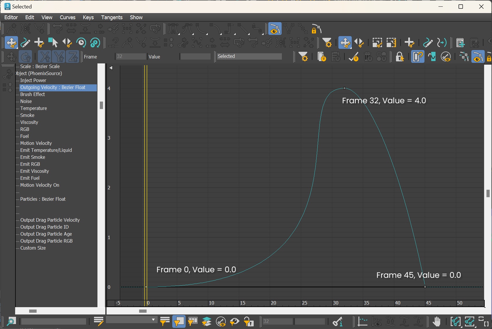
Go to Graph Editors/Track View → Curve Editor and set keys for the Outgoing Velocity of the LiquidSrc_Foam_Splash. By setting keyframes, we can change the particle emission over time. The frames and values for the keyframes are shown in the screenshots.
After setting the keys' tangent to Spline, you need to adjust their left and right handles in order to create the curve shown in the screenshot.
Please note that the animation curves for Outgoing Velocity, as well as those for Foam Particles and Splash Particles later on, are all crafted based on your personal aesthetic sense. Therefore, feel free to adjust the curves according to your needs; there is no absolute correct curve.
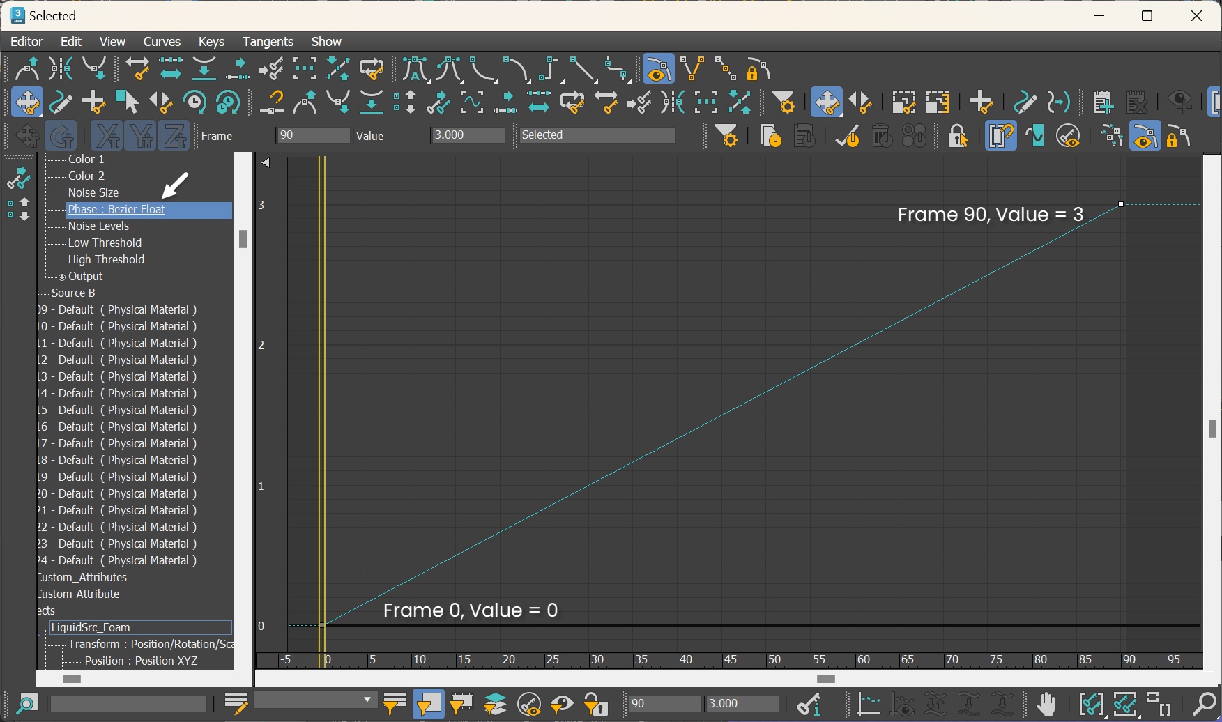
Go to Graph Editors/Track View → Curve Editor and set keys for the Phase of the Noise Parameters of the Noise_for_foam. By setting keyframes, we change the noise pattern over time. The frames and values for the keyframes are shown in the screenshots. Set all tangents to Linear.
Enable the Splash Particles option. Animate the amount of Splash Particles. Plug in a Noise texture map in the Mask slot for the Mask for splash particles emission. Rename the map to Noise_for_splash.
- Set the Noise Type to Fractal.
- Set the Size to 0.635.
- Set the Low value to 0.4
The reason we chose to emit splash particles directly from the whale, instead of the liquid is because, with this grid resolution, emitting liquid results in a thick water blob appearance. In contrast, using splash particles allows us to capture the desired level of detail.
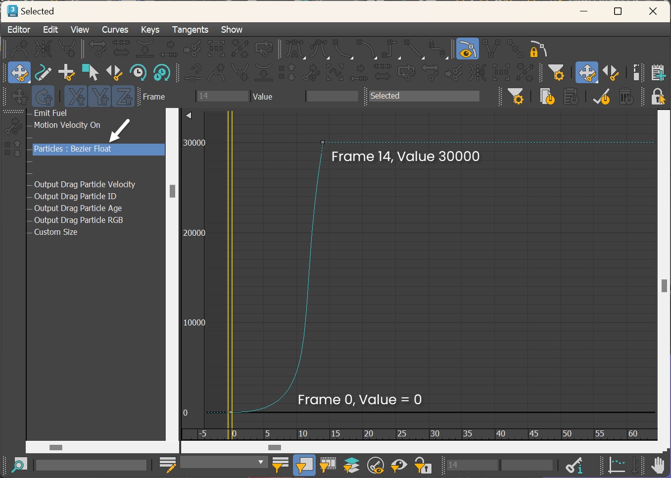
Go to Graph Editors/Track View → Curve Editor and set keys to the curve of the LiquidSrc_Foam_Splash's Splash Particles. We set keyframes for the Splash Particles, so it can change over time.
Note that we avoid generating a large number of splash particles in the initial frames (from frame 0 to frame 1). This precaution is necessary because these splashes transform into water upon colliding with the whale's geometry. With the condition we'll establish in the liquid simulator, and considering that we will enable the liquid source to generate foam particles in later steps, you may encounter unnatural results in the simulation (a significant number of foam particles emitted in a short period as a consequence of the splash particles interacting with the whale geometry). Therefore, it is necessary to assign a low value for the splash particles in the first few frames. You can check the FLIP Particles Life Cycle for more information about particle interaction.
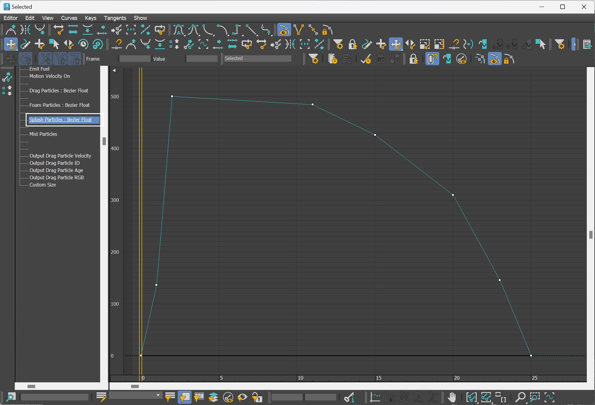
Here is a table with the keyframes of the LiquidSrc_Foam_Splash's Splash Particles.
Frame | Value | Tangent type |
|---|---|---|
0 | 0.000 | Linear |
1 | 136.000 | Linear |
| 2 | 500.000 | Linear |
| 11 | 483.900 | Linear |
| 15 | 425.600 | Linear |
| 20 | 309.700 | Linear |
| 23 | 145.200 | Linear |
| 25 | 0.000 | Linear |
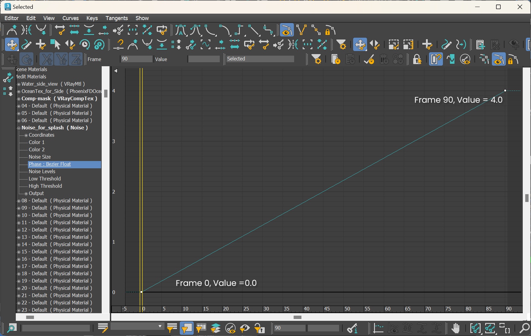
Go to Graph Editors/Track View → Curve Editor, animate the Phase for the Noise Parameter for Noise_for_splash, with a value of 0.0 at frame 0 and 4.0 at frame 90. Set all tangents to Linear.
We animate the phase of the Noise_for_splash texture, so that the splash particles don't emit from the same spot of the whale.
Let's preview the animation of the sim.
We are now all set in regards to splash and mist. Next, let's shift our focus to setting up the foam.
Enable Foam
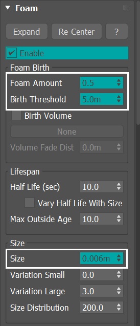
From the Foam rollout of the Phoenix Liquid Simulator, enable the option. A pop out window prompts us to create a Particle Shader for the foam, so select Yes.
Rename the new Particle Shader to ParticleShader_Foam.
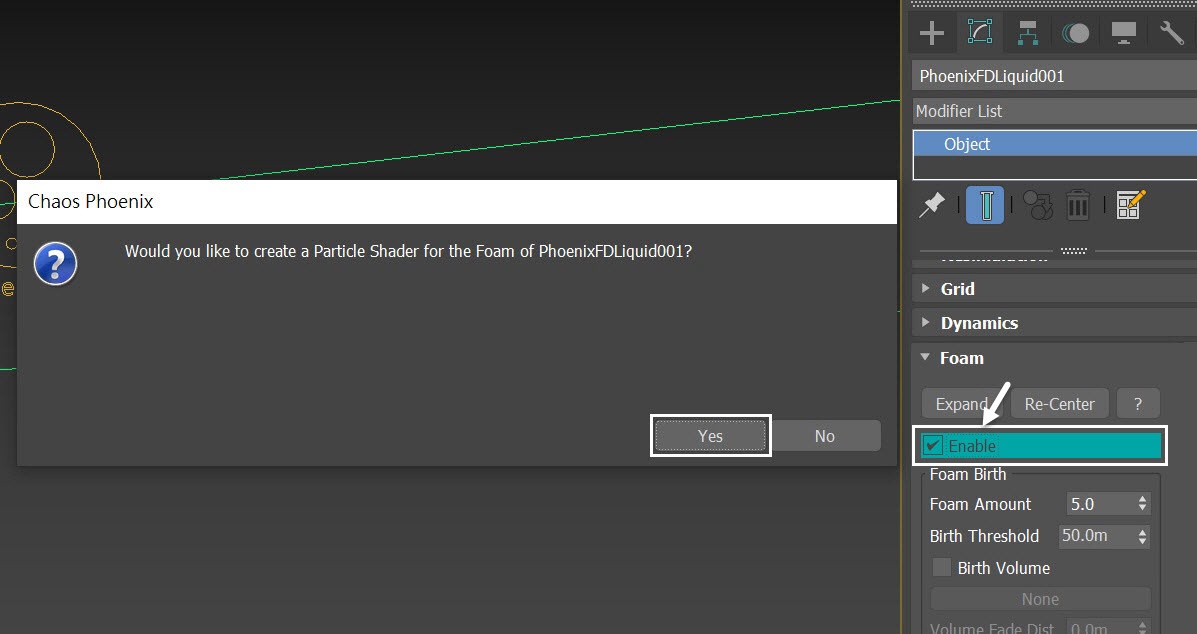
Set the Foam Amount to 0.5. Set the Birth Threshold to 5.0m. Decrease the Size to 0.006 m.
Run the simulation again.
The Foam Size of 0.006 meters (6.0 centimeters) is carefully chosen to achieve a visible foam appearance at camera distance, without appearing overly grainy. You can further adjust the perceived foam size in the Particle Shader by tweaking the Size Multiplier after the simulation is complete.
Let's check the simulation again. There seems to be an issue with the foam shooting out of the sea. Let's address that.
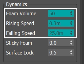
With the simulator selected, go to the Dynamics rollout. Decrease the Foam Volume to 50, reduce the Rising Speed to 0.3m, and decrease the Falling Speed to 25.0m.
Run the simulation again.
Foam Volume controls the internal interaction between bubbles (bubble-to-bubble interaction). This option is used when the foam should have a volume. It forces a proper distance between the bubbles and keeps them stuck together. This parameter controls the number of interactions per second. Higher values result in better preservation of the foam's volume. This parameter has linear growth order. In other words, the time taken for calculation is longer when the value is higher. For more information, see the Foam Volume example.
Here's the corrected simulation.
Improve Foam Pattern Formation
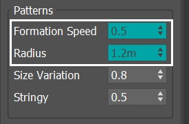
With the Simulator selected, go to the Foam rollout. In the Patterns section, set the Formation Speed to 0.5 and Radius to 1.2m.
Formation Speed controls the rate of formation of foam patterns. In nature, these are caused by liquid flows rising to the surface and pushing the foam aside. For more information, check out the Formation Speed example.
Radius is the average foam radius (in scene units) of a single circular pattern core.
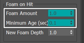
In the Foam on Hit section of the Splash/Mist rollout, set the Foam Amount to 1.0. Set Minimum Age (sec) to 0.1.
With Minimum Age, only splash particles with particle age above this limit, produce foam when they hit the liquid surface.
Enable Foam emission from LiquidSrc_Foam_Splash
To further enhance visual details in the shot, let's enable the foam emission for the LiquidSrc_Foam_Splash.
With the LiquidSrc_Foam_Splash selected, enable the Foam Particles option. Animate the amount of Foam Particles.
Drag and drop the Comp-mask (copy the map as an instance) from the Mask slot of the Outgoing Velocity to the Mask slot of Foam Particles.
Here, we reuse the Comp-mask for the mask of Foam Particles, but you can use any other texture for the mask, as this is about aesthetics, and there is no correct mask for it.
Go to Graph Editors/Track View → Curve Editor and set keys for the Foam Particles amount of the LiquidSrc_Foam_Splash. By setting keyframes, we can change the number of foam particles emitted over time. The frames and values for the keyframes are shown in the screenshots.
After setting the keys' tangent to Spline, you need to adjust their left and right handles in order to create the curve shown in the screenshot.
Now that we are all set for the foam, select the Simulation rollout of the Phoenix Liquid Simulator. The foam formation can be seen in later frames of the animation, so let's enable the Stop Frame and set it to 90.
Press the Start button to simulate.
Let's see the preview animation of the simulation now.
Adding Plain Force
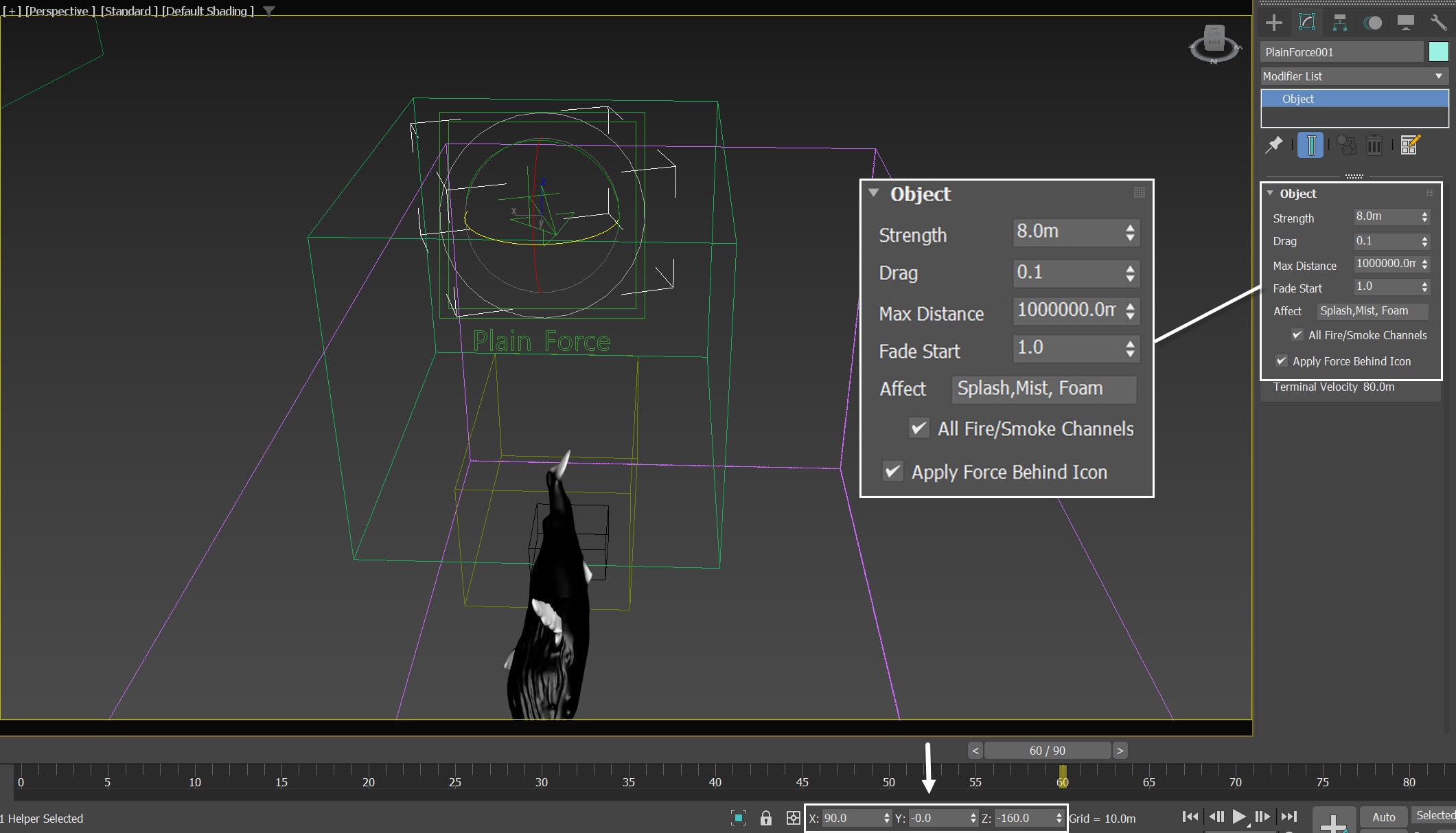
For additional realism of the simulation, we use Phoenix Plain Force, a simple directional force, to simulate the effect of wind.
Go to Create Panel > the Helpers tab > Phenix and add a Phoenix Plain Force.
The exact Position of the Plain Force in the scene is: XYZ[2.7, -13.85, 14.0]
Rotate the Plain Force to XYZ[90.0, 0.0, -160.0]
Set its Strength to 8.0m
Set the Drag to 0.1
Enable the Apply Force Behind Icon option
- Affect Splash, Mist and Foam only, remove other particles from the list
We set the strength of the Plain Force to 8.0m, as this value is strong enough to push Splash, Mist, and Foam particles without being excessively forceful.
Final Simulation
For the final simulation, let's move the simulator and increase its grid resolution and grid size, in order to cover a larger area.
The exact new position of the Simulator in the scene is XYZ: [ -5.6, 14.6, -5.5].
Open the Grid rollout and set the following values:
Cell Size: 0.069m
Size XYZ: [ 416, 758, 368]
Run the final simulation.
Let's take a look at the final simulation.
Shading and Rendering Top View
Set up Particle Shader for Mist
We already have a Particle Shader for Splashes and Foam. For the Mist particles, we have to create a new Particle Shader manually.
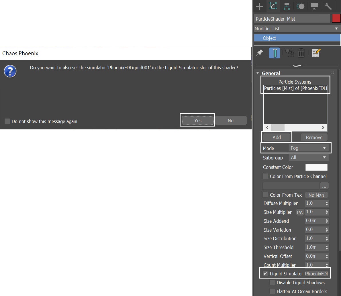
Go to Create Panel→ PhoenixFD and press the PHXFoam button to create a new Particle Shader in the scene. Rename it to ParticleShader_Mist.
Press the Add button and pick the Liquid Simulator, then select the Mist particle group. When doing so, a pop up window prompts you to add PhoenixFDLiquid in the Liquid Simulator slot of the shader, select Yes.
Set the ParticleShader_Mist mode to Fog.
The Liquid Simulator option allows a link to the simulator that produced the shaded particles. When set, the shading of the particles changes when they are inside the liquid volume, as if they are underwater. Also, if the simulator uses Displacement, connecting it to the Particle Shader will displace the particles as well.
Set up Ocean Texture for Displacement
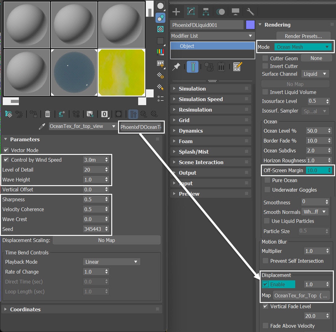
With the PhoenixFDLiquid simulator selected, go to the Rendering rollout and switch the Mode to Ocean Mesh.
Set Off-Screen Margin to 10.0.
The ocean is generated only in the camera view, which can lead to problems when using camera motion blur, using reflections, using refractions with Underwater Goggles enabled, or when the ocean casts shadows on objects underwater. The Off-Screen Margin allows you to extend the ocean further from the borders of the camera view in order to solve such issues.
To add details to the ocean surface, enable the Displacement option. Plug a PhoenixFDOceanTex in the Map slot. The map in the example scene is called OceanTex_for_top_view.
Drag and drop it into the Material Editor as an Instance. The Copy option creates a copy of this map - you want to use the same texture in the simulator and in the material editor instead of being forced to deal with two separate textures, so make sure to choose the Instance option. Rename the texture to OceanTex_for_top_view.
Here are the values for the OceanTex_for_top_view parameters that we use in this tutorial:
- Control by Wind Speed to 3.0m
- Level of Detail to 20
- Sharpness to 0.5
- Velocity Coherence to 0.5
- Wave Crest to 0.0
- Seed: 345443
Velocity Coherence controls the degree of variation in the Wave Direction. When this value is set to 1, all waves move in the same direction, as they do in coastal areas. When set to 0, all waves move in random directions, as they do in open seas.
We deliberately decrease the size of the waves (using the Control by Wind Speed parameter) to establish a sense of proportion, since the top view lacks adequate reference objects for scale. The intention behind this adjustment is to enhance the perceived size of the whale.
Ensure that you set a sufficient value for the Off-Screen Margin. This is important because we use some distortion for the camera. Failing to do so may result in the visible edge of the ocean being seen.
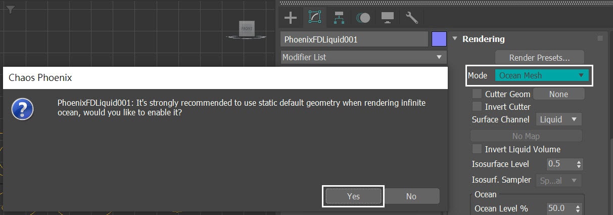
Switch Mode from Cap Mesh to Ocean Mesh. Phoenix prompts the Chaos Phoenix Warning window. Select Yes to use static default geometry.
Water Material
Let's take a look at the water material now.
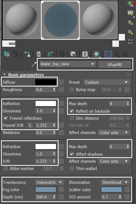
Create a V-Ray Material and assign it to the PhoenixFDLiquid Simulator. Rename the material to Water_top_view.
Set the Diffuse color to black.
Reflect and Refract colors are set to white - it produces a completely transparent material if the Index of Refraction is set to 1 (which is the IOR of clear air). But let's set the IOR to 1.333, which is the physically accurate Index of Refraction of water.
Keep the Max depth to its default value of 8 for both Reflection and Refraction. Enable the Reflect on backside option.
If we render now, we'd notice that the water is completely transparent and looks a bit boring.
Instead, let's switch the Translucency to Volumetric. Set the Fog color to RGB : [46, 75, 102] and set the Depth to 500.0.
Set Scatter color to RGB : [44, 140, 119]. Set Illumination to Directional. Set SSS amount to 0.7. This produces the type of shading expected in a large body of water containing all sorts of particles that interfere with the light rays.
The Reflect on backside option gives you more details in the water shading, hence more realistic results.
Unhide the Plane_Terrain
Unhide the Plane_Terrain in the provided scene. It is a simple plane with a Noise modifier applied to it. This plane serves as underwater terrain for the top view camera.
In the provided scene, the properties of the Plane_Terrain are set to Display as Box, ensuring that it doesn't distract the view in the scene.
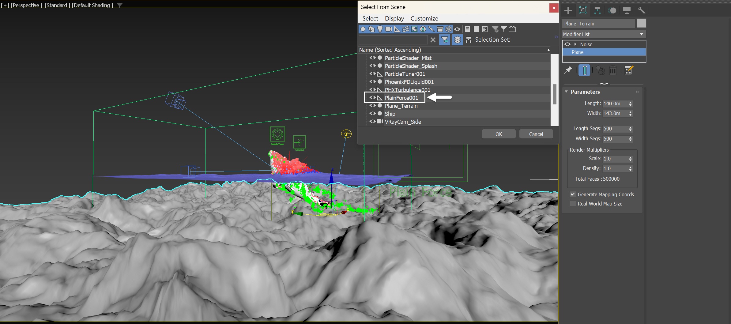
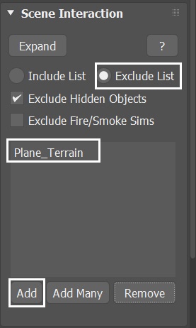
Add the Plane_Terrain to the Exclude List in the Scene Interaction rollout of the simulator. This prevents it from interacting with the fluid simulation.
Run a test rendering. The splash particles look too big. Let's fix the issue by adjusting the Particle Shader's settings in the next step.
Adjust the Particle Shaders
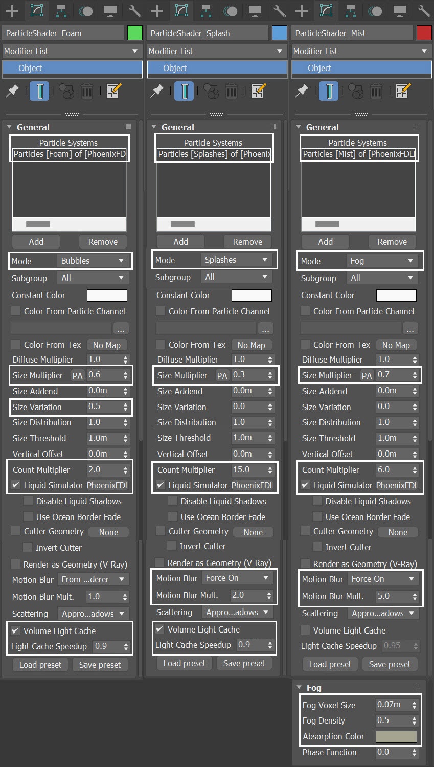
Let's make some adjustments to the Particle Shaders for Foam, Splash and Mist.
For the ParticleShader_Foam:
- Set Mode to Bubbles
- Size Multiplier to 0.6
- Size Variation to 0.5
- Count Multiplier to 2.0
- Enable and set the Light Cache Speedup to 0.9
For the ParticleShader_Splash:
- Set Mode to Splashes
- Size Multiplier to 0.3
- Count Multiplier to 15.0
- Motion Blur to Force On, Motion Blur Mult. to 2.0
- Enable and set the Light Cache Speedup to 0.9
To maintain the volume of the liquid splash, we increase the Count Multiplier when decreasing the particle size in the Particle Shader. The formula for the Count Multiplier is (1/Size Multiplier) ^ 3. In this particular case, we set the Size Multiplier to 0.3, resulting in a calculation of (1/0.7)^ 3 = 37.037. However, we need to consider the rendering performance when using such a high Count Multiplier. In this case, a value of 15.0 for the Count Multiplier suffices for the visual.
If you notice flickering in the rendered animation, consider reducing the Light Cache Speedup for the foam and splash particles. In this example, the value is set to 0.9. The Light Cache Speedup can significantly reduce render times.
For the ParticleShader_Mist:
- Set Mode to Fog
- Size Multiplier to 0.7
- Count Multiplier to 6.0
- Motion Blur to Force On, Motion Blur Mult. to 5.0
- Disable Volume Light Cache. Volume Light Cache enables light caching, which can speed up bucket rendering considerably, but enabling this option here might cause GI flickering in the mist particles rich area.
- Set Fog Voxel Size to 0.07m
- Increase Fog Density to 0.5
- Absorption Color to RGB[96, 96, 72]. The Absorption Color can affect the opacity of the fog as well, depending on how bright or dark its color is. Brighter colors make the volume more transparent, while darker colors make it more opaque (denser).
When using V-Ray progressive rendering, the Volume Light Cache option might slow down rendering startup or the overall render speed. This option refers to the internal Phoenix Light Cache, which is unrelated to the V-Ray Light Cache.
When using a high motion blur value for splashes and mist, it reduces the granularity of the particles in the rendering. This is especially beneficial for the initial frames when the whale surfaces, and when it impacts the water upon fall.
You can achieve significant rendering performance gains by switching the Mode of the Foam and Splash in the Particle Shaders to Points (which sacrifices realism in the image). However, when doing so, ensure that you increase the Size Multiplier to maintain the overall appearance. In such case, set the Size Multiplier to 0.8 for the Foam and 0.4 for the Splashes. Additionally, you need to enhance the motion blur for the particle shaders, as rendering with Point Mode makes the motion blur appear weaker. Set the Motion Blur Multiplier to 5 for the Splash's Particle Shader to compensate for this.
Feel free to adjust the settings for those Particle Shaders, in terms of Size Multiplier and Count Multiplier to fit your artistic taste.
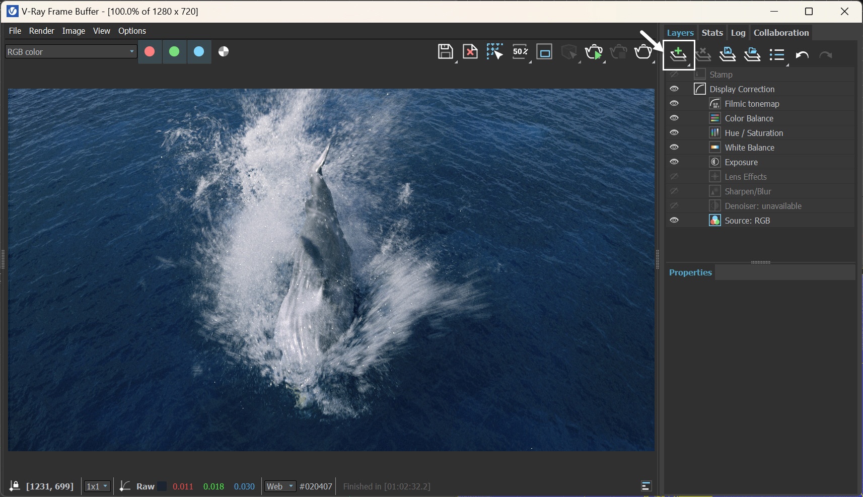
V-Ray Frame Buffer
Run a test rendering. Now the particles are smaller, while maintaining overall volume.
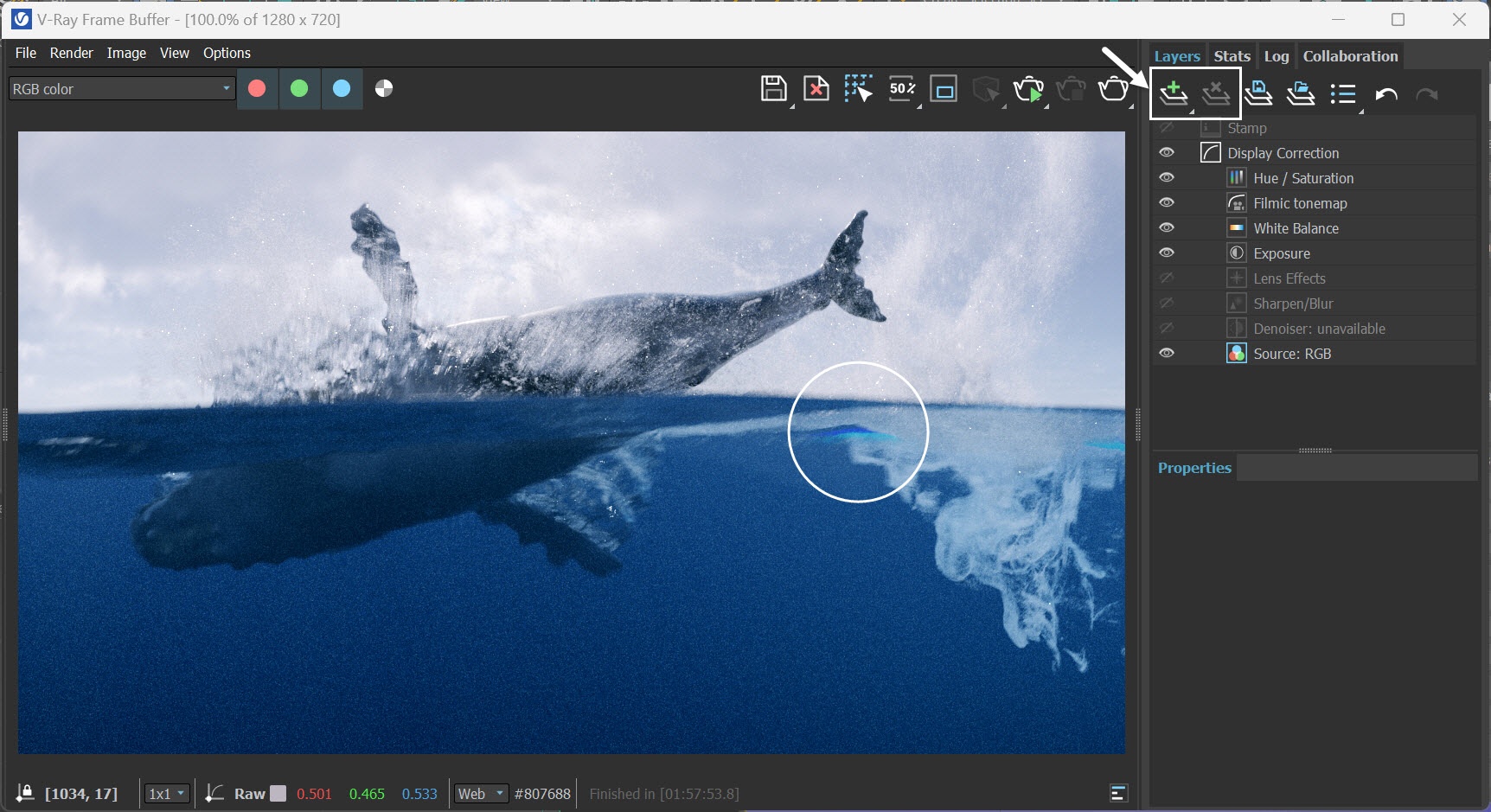
To further fine-tune the image, use the Create Layer icon in the V-Ray Frame Buffer to add layers for Exposure, White Balance, Hue / Saturation, Color Balance and Filimic tonemap adjustments.
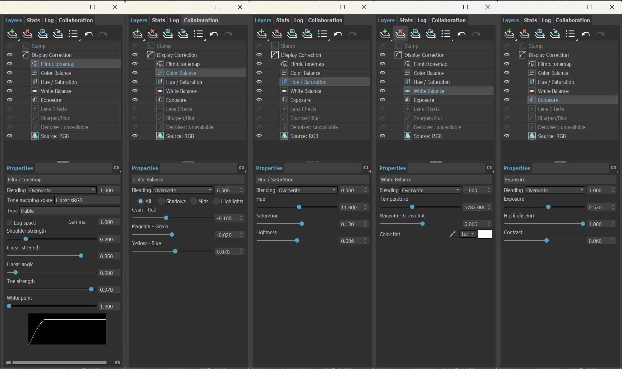
The final image is rendered using the V-Ray Frame Buffer with the color corrections and post effects set to:
Filmic tonemap:
Type - Hable
Shoulder strength: 0.200
Linear strength: 0.850
Linear angle: 0.080
Toe strength: 0.970
White point: 1.000
Color Balance:
Blending: Override, set to 0.50
Cyan-Red: -0.16
- Magenta-Green: -0.02
- Yellow-Blue: 0.07
Hue / Saturation:
Blending: Override, set to 0.50
Hue: 11.80
Saturation: 0.130
Lightness: 0.006
White Balance:
Temperature: 5782.000
Magenta - Green tint: 0.066
Exposure:
Exposure: 0.520
Highlight Burn: 1.000
Contrast: 0.06
Feel free to use other values for the post effects depending on your preferences.
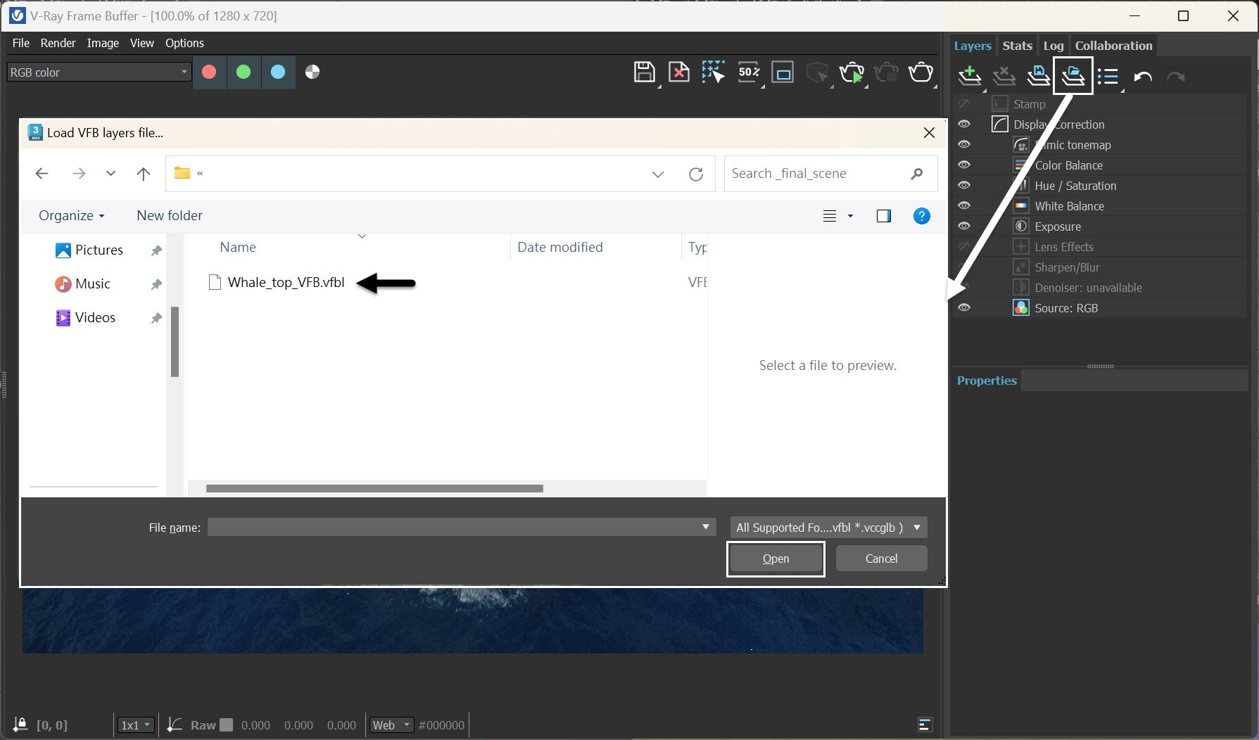
Alternatively, you can load a layer tree Preset from the Whale_top_VFB.vfbl file provided in the packed scene.
And here is the final rendered result from the VRayCam_Top camera.
Let's continue working on the side view.
Shading and Rendering Side View
Set up Ocean Texture for Displacement
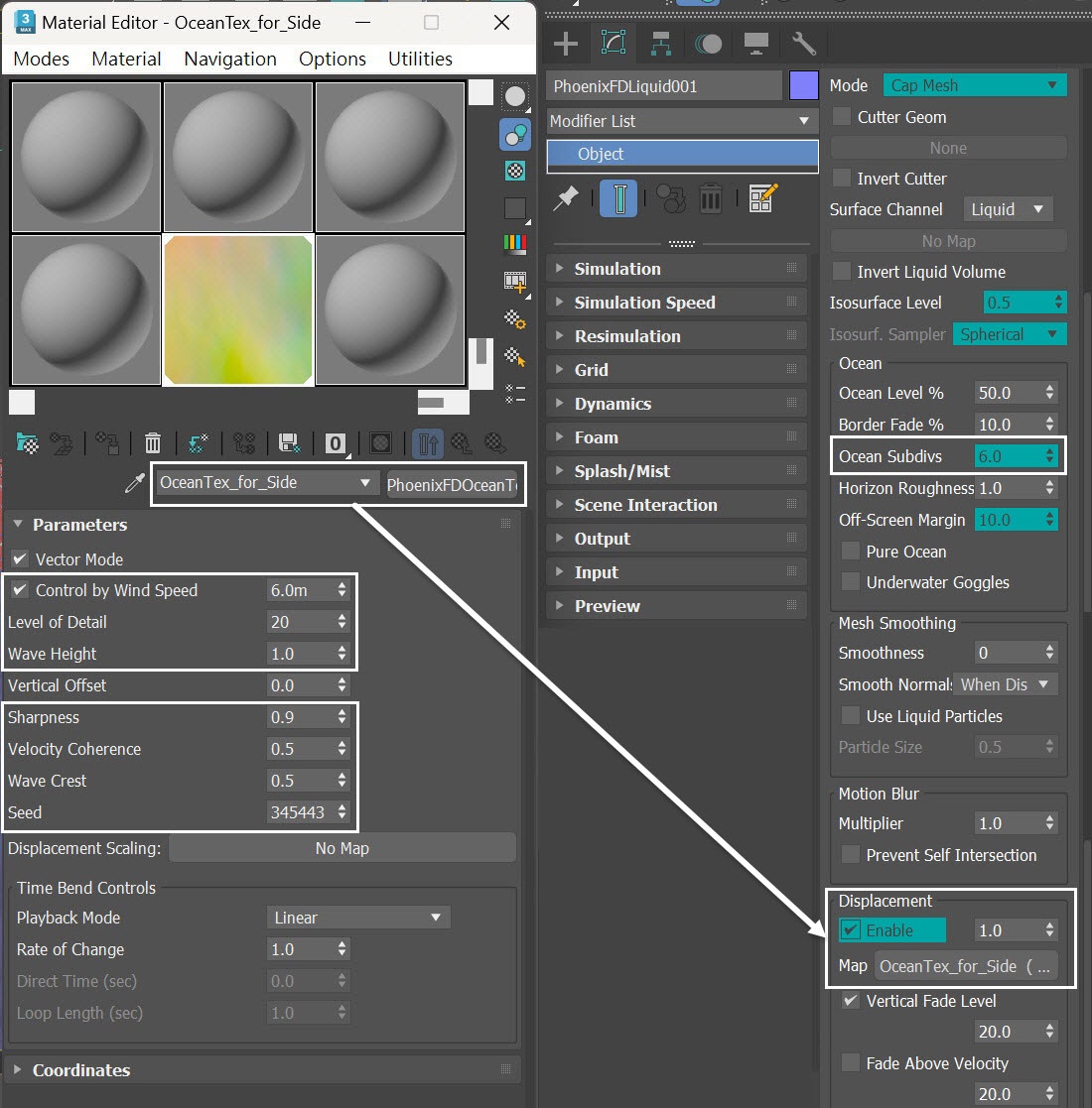
We want to have a stronger wave for the side view. With the PhoenixFDLiquid simulator selected, plug a PhoenixFDOceanTex into the Map slot, replacing the existing one, and rename it to OceanTex_for_Side.
Here are the values for the OceanTex_for_Side parameters that we use in this tutorial:
- Control by Wind Speed to 6.0m
- Level of Detail to 20
- Wave Height to 1.0
- Sharpness to 0.9
- Velocity Coherence to 0.5
- Wave Crest to 0.5
- Seed: 345443
Increase the Ocean Subdives to 6.0.
We increased the Ocean Subdives to 6.0 in order to reduce the horizon flickering.
Create a Box for Cutter Geom
In the following steps, we create a section for the ocean to achieve a seamless transition between underwater and above water shot. To accomplish this, we need to use a dedicated geometry in the Simulator's Cutter Geom. Let's proceed with creating this geometry.
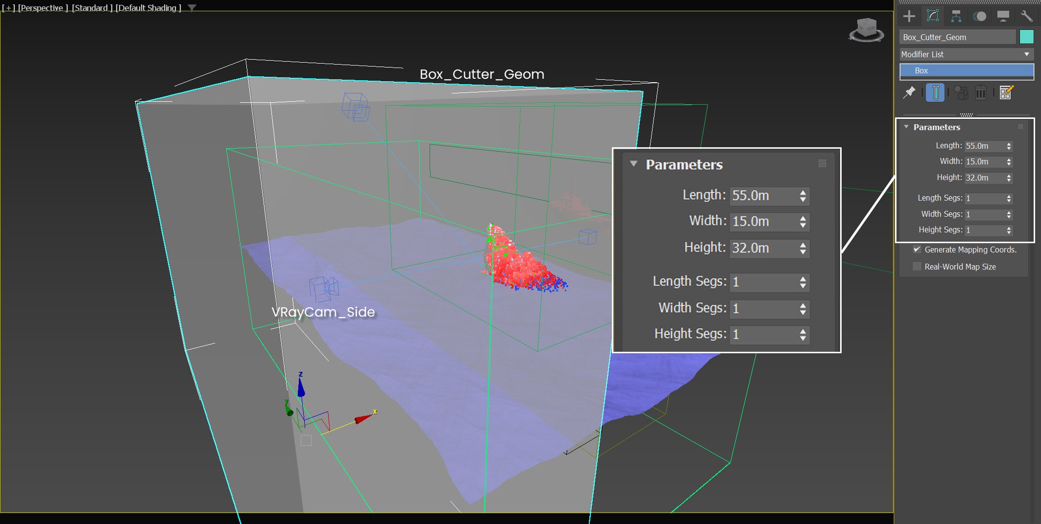
Go to Create Panel → Geometry → Standard Primitives → Box . Create a box in the scene. Rename the box to Box_Cutter_Geom.
Set its Length, Width and Height to 55m, 15.0m and 31.75m, respectively. Segs from all sides to 1.
The exact position of Box_Cutter_Geom is XYZ: [-21.0, 14.6, -6.8 ].
Note that the Camera_Side is positioned inside the simulator grid, so when you apply a cutter geometry to the simulator, it can generate a section of the ocean with better topology. Additionally, the volume of the Box_Cutter_Geom intersects with the simulator, as shown in the screenshot. Pay attention to these details to ensure you get the ocean cross-section you desire.
We temporarily set the Display properties of the Box_Cutter_Geom to See-Through, allowing for better visibility of the relative positions of the VRayCam_side, the simulator grid, and the Box_Cutter_Geom.
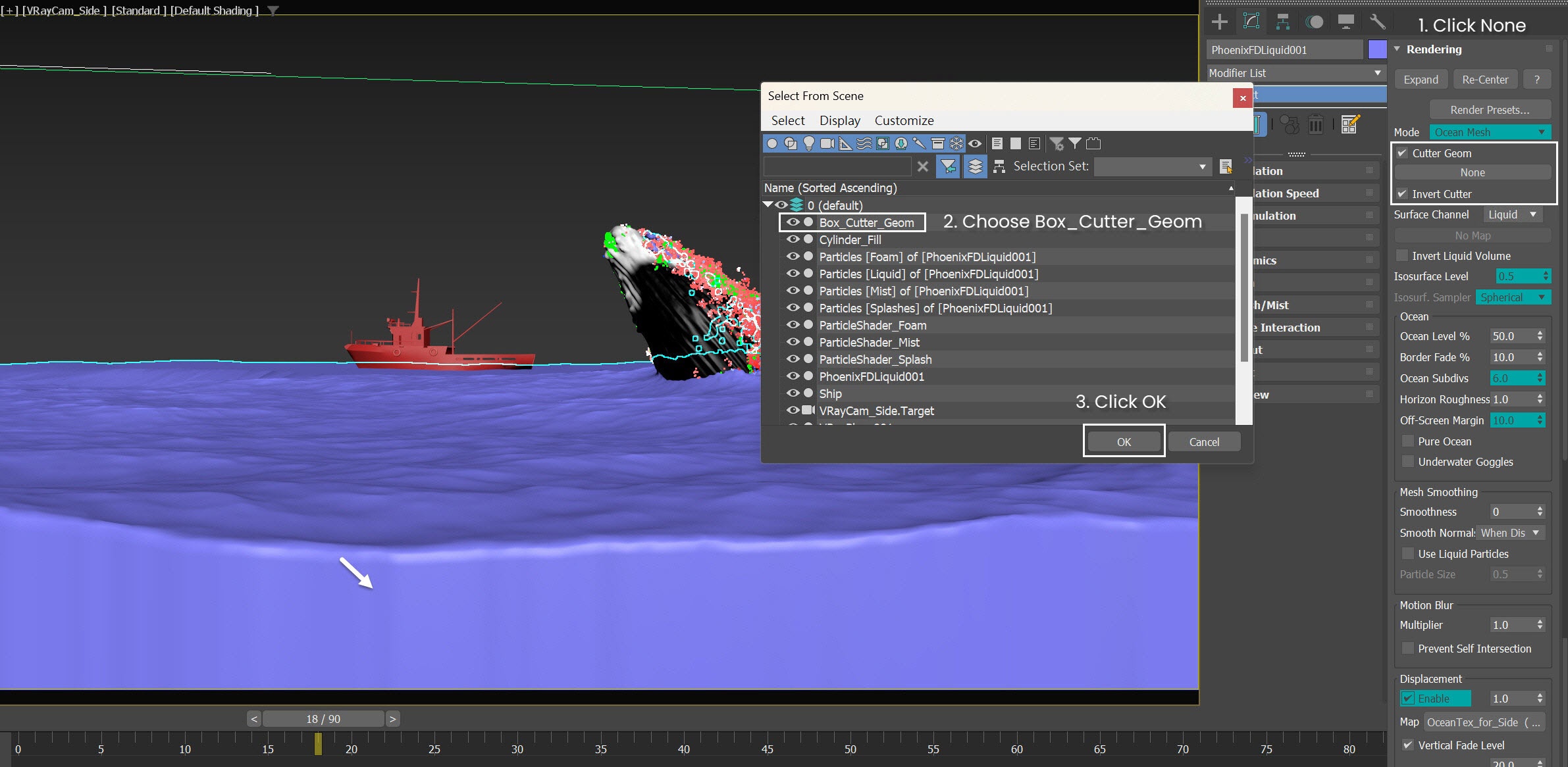
In the Rendering rollout of the LiquidSimulator, click the None button for the Cutter Geom. Then, choose the Box_Cutter_Geom that we just created and click OK. Enable both the Cutter Geom and Invert Cutter options.
Now we have the ocean section's façade, but as you can see, there are some waves in the mesh, caused by displacement effects to the ocean surface.
Create a Box for Fade Volume
Let's create an additional box to mitigate the wavy appearance in the ocean section by fading off the effect of displacement.
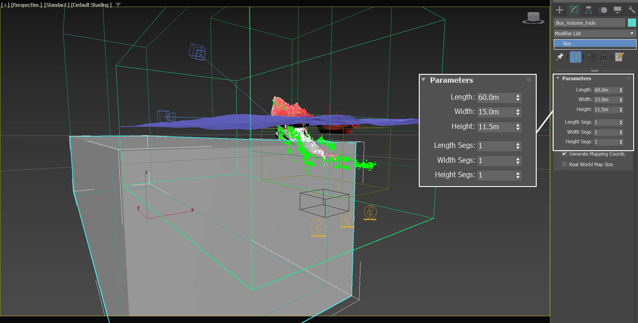
Go to Create Panel → Geometry → Standard Primitives → Box . Create a box in the scene. Rename the box to Box_Volume_Fade.
Set its Length, Width and Height to 60.0m, and 15.0m and 12.0m respectively. Segs from all sides to 1.
The exact position of Box_Volume_Fade is XYZ: [-21, 14.62, -6.4 ].
We temporarily set the Display properties of the Box_Volume_Fade to See-Through, allowing for better visibility of the relative positions of the VRayCam_side, the simulator grid, and the Box_Volume_Fade .
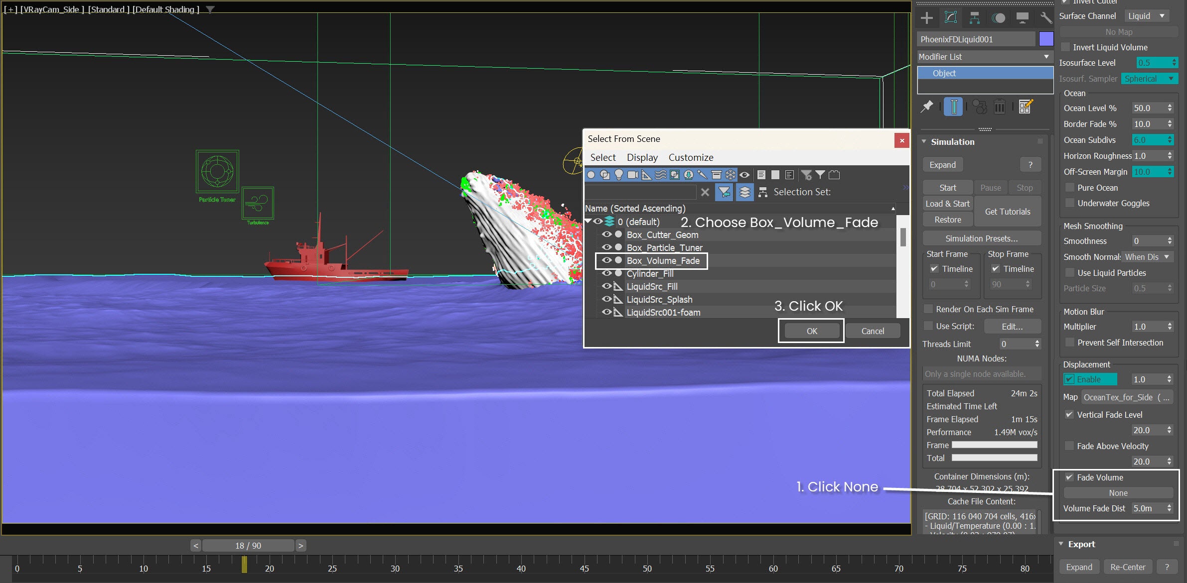
In the Rendering rollout of the LiquidSimulator, click the None button for the Volume Fade option. Then, choose the Box_Volume_Fade and click OK. Enable the Volume Fade option. Change the Volume Fade Dist to 5.0m.
Now we achieved a significantly smoother ocean section, while still preserving some of the displacement effects on the surface of the ocean section.
You can adjust the height and position of the Box_Volume_Fade, along with the value for the Volume Fade Distance, to achieve a good balance between a strong displacement effect and minimizing the wavy appearance in the ocean section façade.
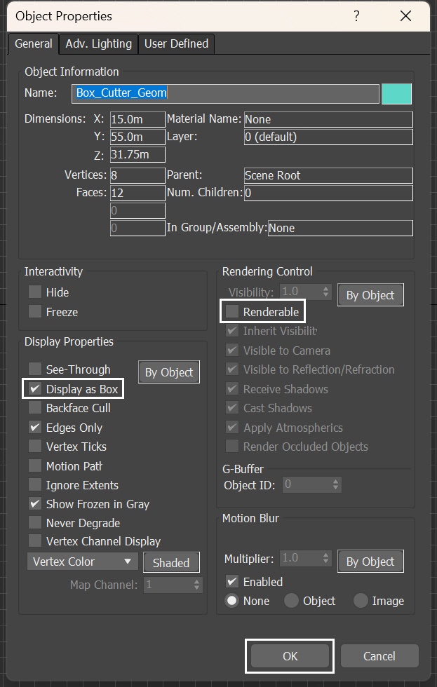
We create two boxes for the ocean section, specifically for the Cutter Geom functionality and they don't need to be rendered.
Let's select the Box_Cutter_Geom, right-click on it, go to Object Properties. Check the Display as Box option and disable Renderable. Repeat the same procedure for the Box_Volume_Fade.
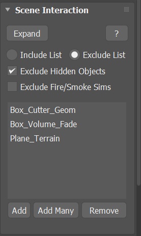
In addition to the rendering settings, make sure to add the Box_Volume_Fade and Box_Cutter_Geom to the Exclude List in the Scene Interaction rollout of the simulator. Although we completed the simulation phase at this stage, this step prevents the geometries from interacting with the fluid, in case we decide to perform additional simulations.
Block bottom light
Hide the Plane_Terrain in the scene.
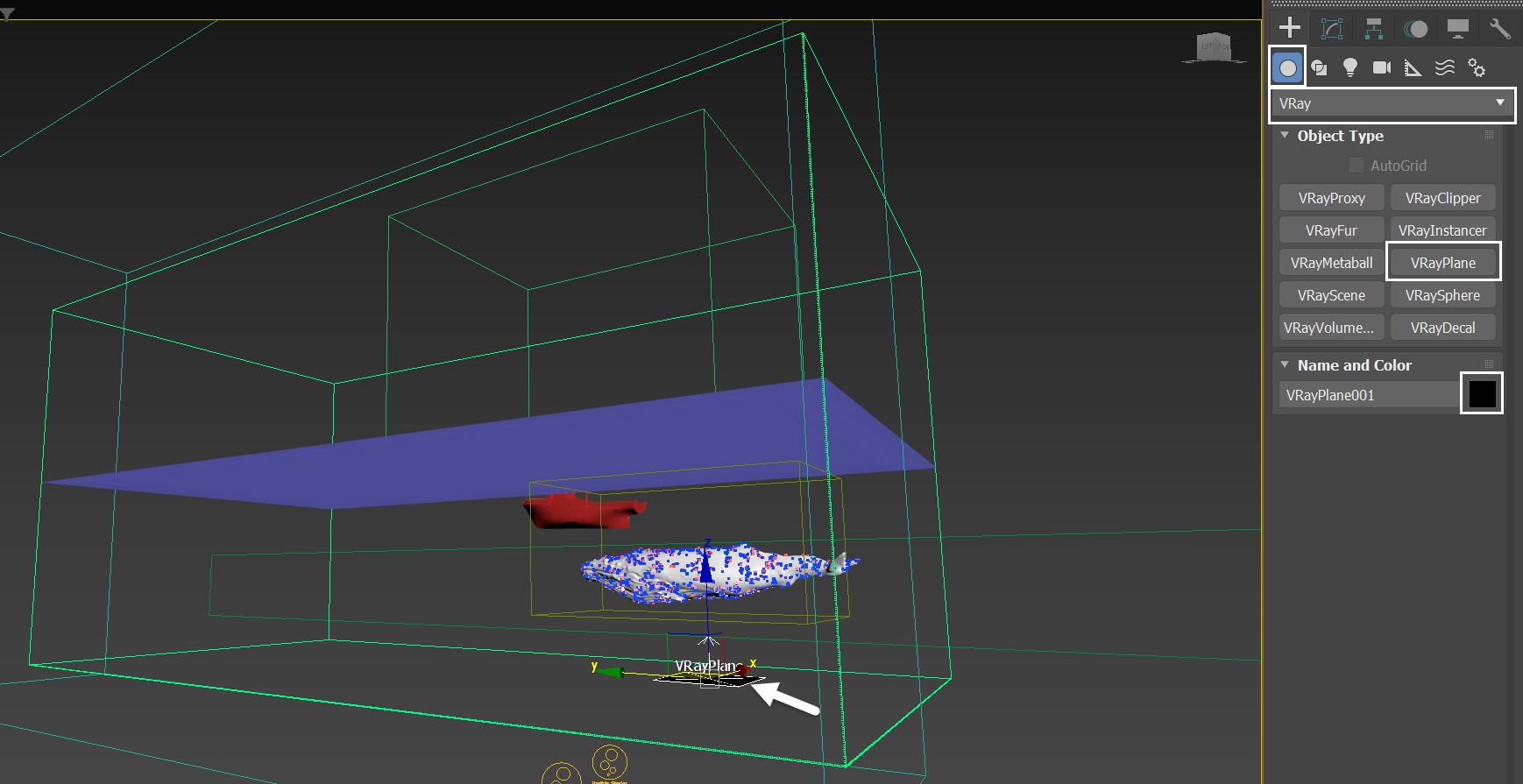
Go to Create Panel → Geometry → VRay and press the VRayPlane button. Create a VRayPlane in the scene. Change it's Object Color to black. The V-Ray plane is used to block light from the bottom during rendering, and does not affect the simulation.
The exact position of the VRayPlane is XYZ: [0.0, 0.0, -5.49 ].
The VRayPlane is positioned slightly above the bottom of the liquid simulator.
Run a test render for the Camera_side.
We re-use the Particle Shader and the VFB settings, as well as the water material from the side view.
However, the sky is overexposed, the water is too opaque, and the splash shading needs more work. Let's tailor these elements specifically for the side view camera.
We render frame 18 as a representative frame for a test rendering. However, feel free to select any other frame(s) of your preference.
Water Material
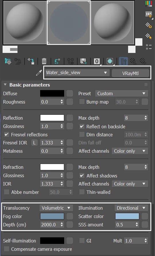
Let's take the existing Water_top material, and rename it to Water_side_view. Apply the material to the Simulator.
Make the Scatter color lighter to RGB : [86, 136, 182]. Decrease the SSS amount to 0.5.
Increase Depth to 2000.0.
Our objective is to increase light penetration in depth and intensify the brightness of the water color. However, feel free to adjust the values according to your personal preference.
Adjust the Particle Shaders
Due to the high computational demand of rendering this scene, let's prioritize foam over splashes for the side view. Let's fine-tune the Particle Shaders to enhance the prominence of the foam, while reducing the emphasis on splashes for this camera.
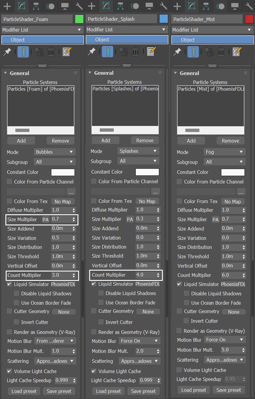
For the ParticleShader_Foam:
- Increase Size Multiplier to 0.7
- Increase Count Multiplier to 3.0
For the ParticleShader_Splash:
- Decrease Count Multiplier to 4.0
For the ParticleShader_Mist, leave everything unchanged.
Keep in mind that in order to maintain the volume of the liquid splash, we increase the Count Multiplier, while decreasing the particle size in the Particle Shader. The formula for the Count Multiplier is (1/Size Multiplier) ^ 3. However, in this case, we deviate from the formula to achieve better rendering performance.
Again, feel free to adjust the settings for those Particle Shaders, in terms of Size Multiplier and Count Multiplier to fit your artistic taste.
V-Ray Frame Buffer
With the new water material applied, and with adjusted Particle Shaders, let's run a test rendering.
The previous render had some overexposure. Let's make some adjustments in the VFB to avoid that. Use the Delete selected layers icon to remove the Color Balance layer. Click on each layer and tweak their values.
Now everything looks good, except for one strange color band near the waterline (see the screenshot).
This is caused by the nature of the Fog color parameter in the VRay Material, which is essentially a 2D effect. We need to an extra step to mitigate the banding.
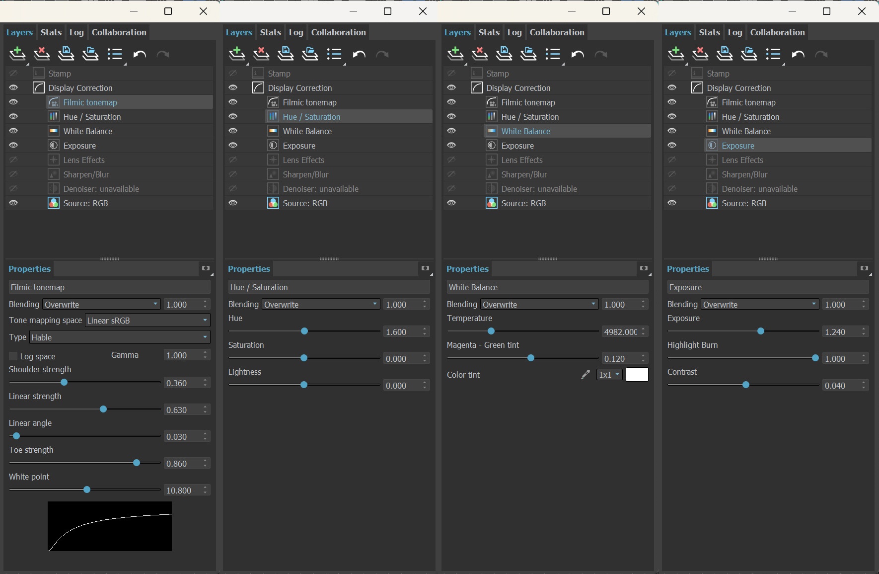
The final image is rendered using the V-Ray Frame Buffer with the color corrections and post effects set to:
Filmic tonemap:
Type - Hable
Shoulder strength: 0.360
Linear strength: 0.630
Linear angle: 0.030
Toe strength: 0.860
White point: 10.800
Hue / Saturation
Hue: 1.600
Saturation: 0.000
Lightness: 0.000
White Balance:
Temperature: 4982.000
Magenta - Green tint: 0.120
Exposure:
Exposure: 1.240
Highlight Burn: 1.000
Contrast: 0.00
Feel free to use other values for the post effects depending on your preferences.
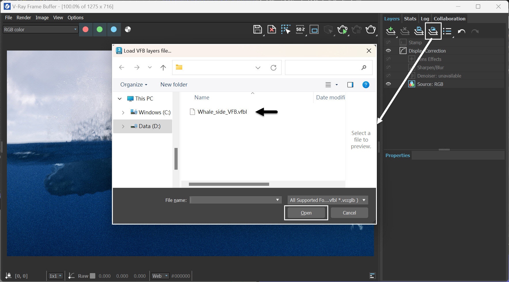
Alternatively, you can load a layer tree Preset from the Whale_side_VFB.vfbl file, provided in the packed scene.
Create a Plane for the Color Banding
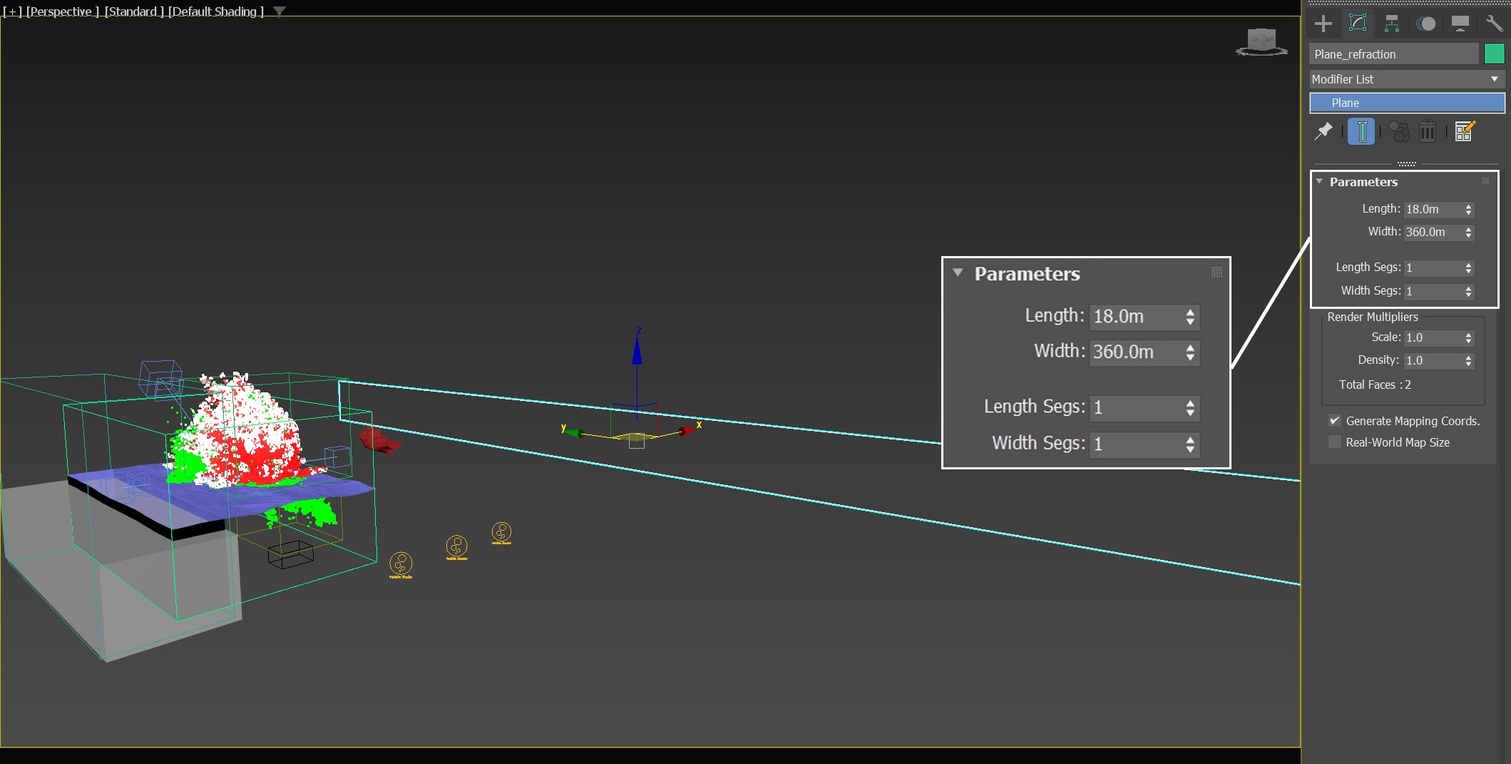
Go to Create Panel → Geometry → Standard Primitives → Plane. Create a plane in the scene. Rename it to Plane_refraction.
Set its Length and Width to 18.0 m, and 360.0m, respectively. Segs from all sides to 1.
The exact position of Plane_refraction is XYZ: [109.0, 13.0, -1.83 ].
Apply the same water material (Water_side_view) to Plane_refraction.
The placement and dimensions of the Plane_refraction effectively extend the coverage to the submerged portion of the ocean mesh, encompassing the underwater façade from the Camera_side perspective. This way the plane acts as a closing surface for the ocean and fixes the color banding.
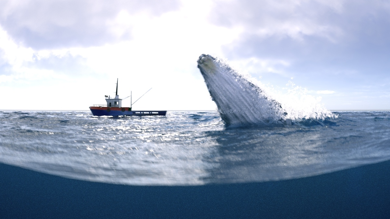
With the Plane_refraction in the scene, render the sequence for Camera_Side. Here is the final rendered result, with the color banding issue successfully eliminated.
Now that we rendered Camera_top and Camera_side, let's put these two sequences together using any video editing software to create a combined sequence.