Introduction
In this chapter we'll cover the V-Ray Displacement functionality.
Displacement mapping is a technique for adding detail to your scene geometry without having to model it first. The concept is very similar to bump mapping. However, bump mapping is a shading effect that only changes the appearance of a surface, while displacement mapping actually modifies the surface.
The V-Ray Displacement Modifier adds displacement to geometry. While it is similar in function to some standard host application modifiers and other displacement tools built into them, GeomDisplacedMesh provides a number of additional controls for fine-tuning the displacement and is optimized to work with the V-Ray renderer.
It is very useful in architecture, where floors, walls, latticework, grass need to be displayed in detail.
There are generally 3 types of mapping which the user can use - 2D mapping (landscape), 3D mapping and subdivision. 2D mapping is suitable for lower RAM usage, but cannot guarantee that the surface of different sides of the object is continuous. 3D mapping solves this, but consumes a lot more memory.
Parameters
The following parameters reside in the GeomDisplacedMesh plugin. The global parameters are in the SettingsDefaultDisplacement plugin.
- mesh - The triangle mesh that will be displaced
- displacement_tex_color - The displacement texture. This can be any texture map such as a bitmap, procedural map, 2D or 3D map, etc.
- displacement_tex_float - The displacement texture
- displacement_amount - Determines the displacement amount for white areas in the displacement map; if use_globals is true this is multiplied by the global displacement amount option. A value of 0.0 means the object will appear unchanged (or simply smoothed, if the Subdivision method is selected). Higher values produce a greater displacement effect. This value can also be negative, in which case the displacement will push geometry inside the object.
- displacement_shift - This constant value is added to the displacement map. It effectively shifts the displaced surface up and down along the normals. This value can be either positive or negative. For more information, see the Shift example below.
- use_globals - If true, the global displacement quality settings will be used.
- view_dep - If use_globals is false, this determines if view-dependent tesselation is used. When this option is enabled, the Edge length value determines the maximum length of a subtriangle edge in pixels, and a value of 1.0 means that the longest edge of each subtriangle will be about one pixel long when projected on the screen. When this option is disabled, Edge length is the maximum subtriangle edge length in world units.
- edge_length - If use_globals is false, this determines the approximate edge length for the sub-triangles. This affects the degree of subdivision before displacement, which in turn affects the quality of the displacement itself. Each triangle of the original mesh is subdivided into a number of subtriangles. More subtriangles mean more detail in the displacement, slower rendering times and more memory usage. Less subtriangles mean less detail, faster rendering and less memory used. Units used for this parameter depend on the View-dependent parameter. For more information, see the Edge Length example below.
- max_subdivs - If use_globals is false, this determines the maximum subdivisions for a triangle of the original mesh. The value is in fact the square root of the maximum number of subtriangles. For example, a value of 256 means that at most 256 x 256 = 65536 subtriangles will be generated for any given original triangle. It is not a good idea to keep this value very high. If you need to use higher values, it will be better to tessellate the original mesh itself into smaller triangles instead. The actual subdivisions for a triangle are rounded up to the nearest power of two (this makes it easier to avoid gaps because of different tessellation on neighboring triangles).
- keep_continuity - If true, the plugin will attempt to keep the continuity of the displaced surface. Use it when you get splits (usually around sharp edges) in the displaced geometry due to different smoothing groups and/or material IDs on adjacent faces. Note that using material IDs is not a very good way to combine displacement maps since V-Ray cannot always guarantee the surface continuity. Use other methods (vertex colors, masks etc) to blend different displacement maps. For more information, see the Keep Continuity example below.
- water_level - Geometry below this displacement level will be clipped away. For more information, see the Clip Mapping example below.
vector_displacement - If using a displacement texture that is not grayscale, V-Ray will convert it to grayscale before rendering the displaced geometry. This mode allows V-Ray to use the Red, Green, and Blue channels of the displacement texture to displace the geometry in the U and V directions in addition to the direction of the face normal. Possible values are:
- 0 - Disabled – No vector displacement; regular displacement along the surface normal will be used.
- 1 - Tangent – The texture is interpreted as 0.5-based tangent space displacement map.
- 2 - Object – Only meaningful when a TexPtex texture is used for displacement, where the texture values represent 0-based displacement in object space. If mesh information is stored in the Ptex file, V-Ray can also displace correctly mesh deformations. Object-space Ptex vector displacement only works for subdivision surfaces when the displacement Type is Subdivision. For more information, see the Vector Displacement example below.
map_channel - The mapping channel to use for vector and 2d displacement.
- image_width - This parameter overrides the imgWidth parameter from VRayFrameData during the calculation of the subdivision depth.
- object_space_displacement - If true, the parent transformation will affect the amount of displacement. Used only when doing 3D displacement.
- use_bounds - If true, the min/max values for the displacement texture are specified by the
min_boundandmax_boundparameters; if false, these are calculated automatically. - min_bound - The lowest value for the displacement texture. By default, this and the next option are limited to values between 0 and 1. For more information, see the Texture Boundaries example below.
- max_bound - The biggest value for the displacement texture.
- displace_2d - Use to enable 2d displacement. Overrides the vector_displacement flag.
- displace_2d_multi_tile - Enable or disable support for tiled textures (UDIM/UVTILE) when generating 2d displacement.
- resolution - Resolution at which to sample the displacement map for 2d displacement. If the texture map is a bitmap, it is best to match this resolution to the size of the bitmap. For procedural 2D maps, set the resolution according to the desired quality and detail in the displacement. Note that V-Ray will also automatically generate a normals map based on the displacement map to compensate for details not captured by the actual displaced surface.
- precision - Increase for curved surfaces to avoid artifacts.
- filter_texture - Filter the texture for 2d displacement.
- filter_blur - The amount of UV space to average for filtering purposes. A value of 1.0 will average the whole texture.
Related to performance
- tight_bounds - When this is on, initialization will be slower, but tighter bounds will be computed for the displaced triangles making rendering faster.
- static_displacement - If true, the resulting triangles of the displacement algorithm will be inserted into the rayserver as static geometry. This means the displacement geometry is pre-compiled into an acceleration structure at the beginning of the rendering and remains there until the end of the frame. This can speed up the rendering but will increase the memory usage. Note: When rendering on the GPU with displacement, all geometry is pre-compiled.
- cache_normals - If this option is equal to 1 then the normals of the generated triangles are cached. This requires additional memory but speeds up the shading calculations during rendering. Note: This option is always on when rendering on the GPU. Enabling this option is not recommended with low displacement settings.
Examples
The following scenes are rendered by using this scene bundle. You can comment/uncomment different sections from the scene and see the comments in the included ones.
Normal Displacement type - Rough Quality
Normal Displacement type - Fine Quiality
2D Displacement type - Rough Quality
2D Displacement type - Fine Quality

2D Displacement type - Water Level 0, 1 and 4 respectively

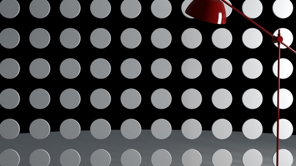
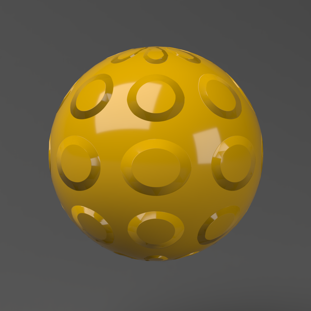
Displacement vs Bump Mapping
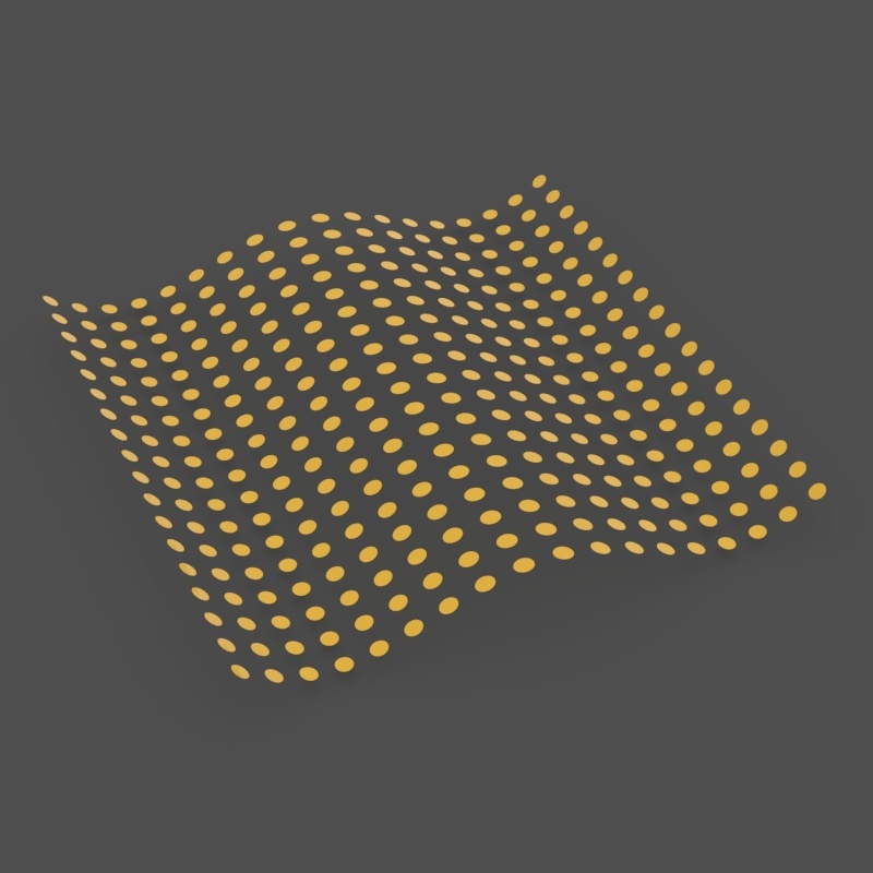
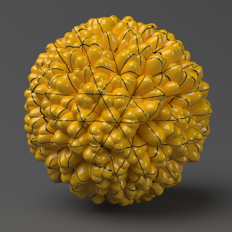
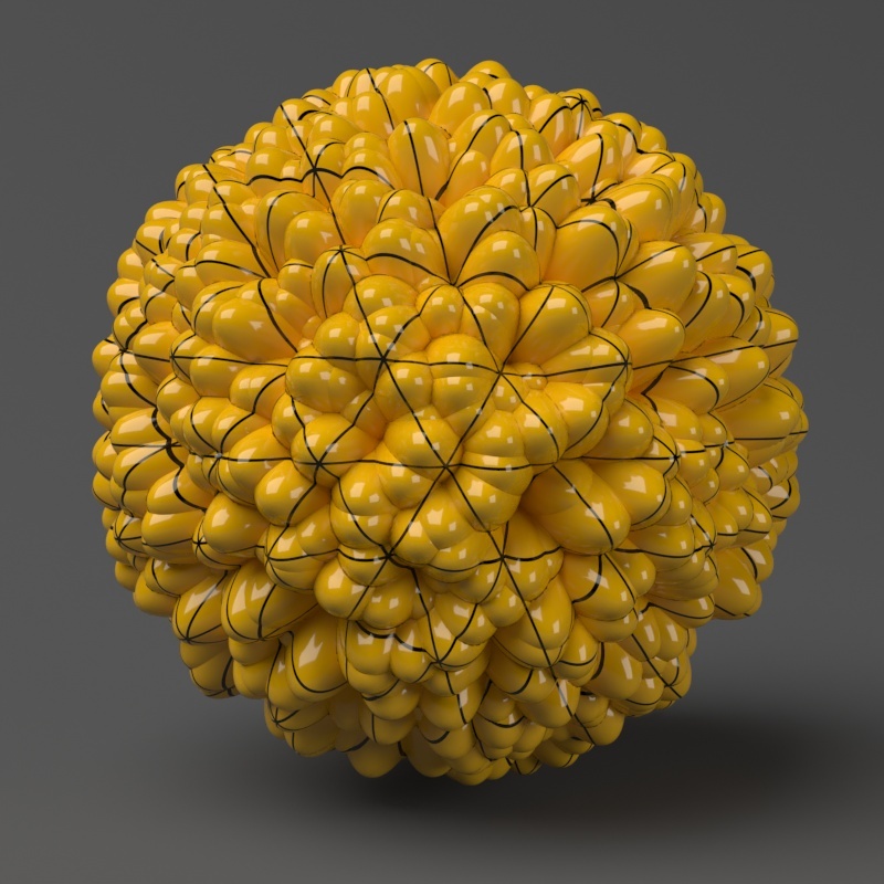
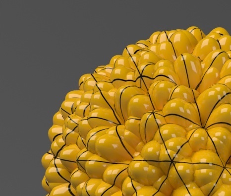
This example shows the difference between bump mapping and displacement mapping. Notice the round outline of the sphere and its shadow in the case of bump mapping, and the deformed outline produced by the displacement. The displacement map in this case is a 3D Gradient Ramp (procedural) map; the 3D mapping method was used.
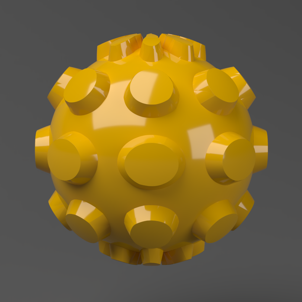
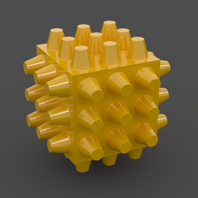
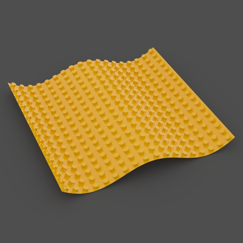
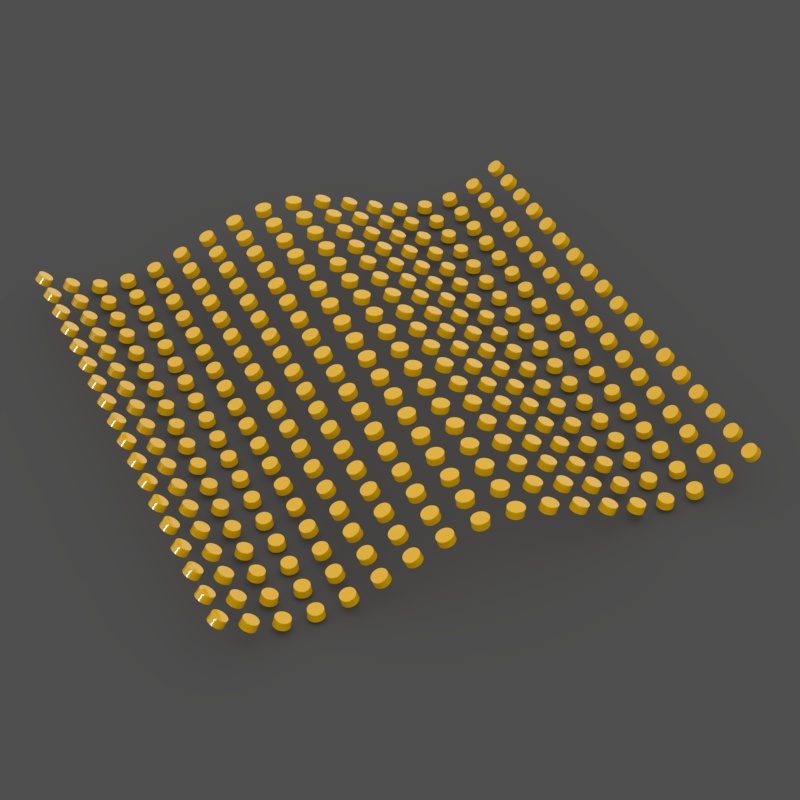
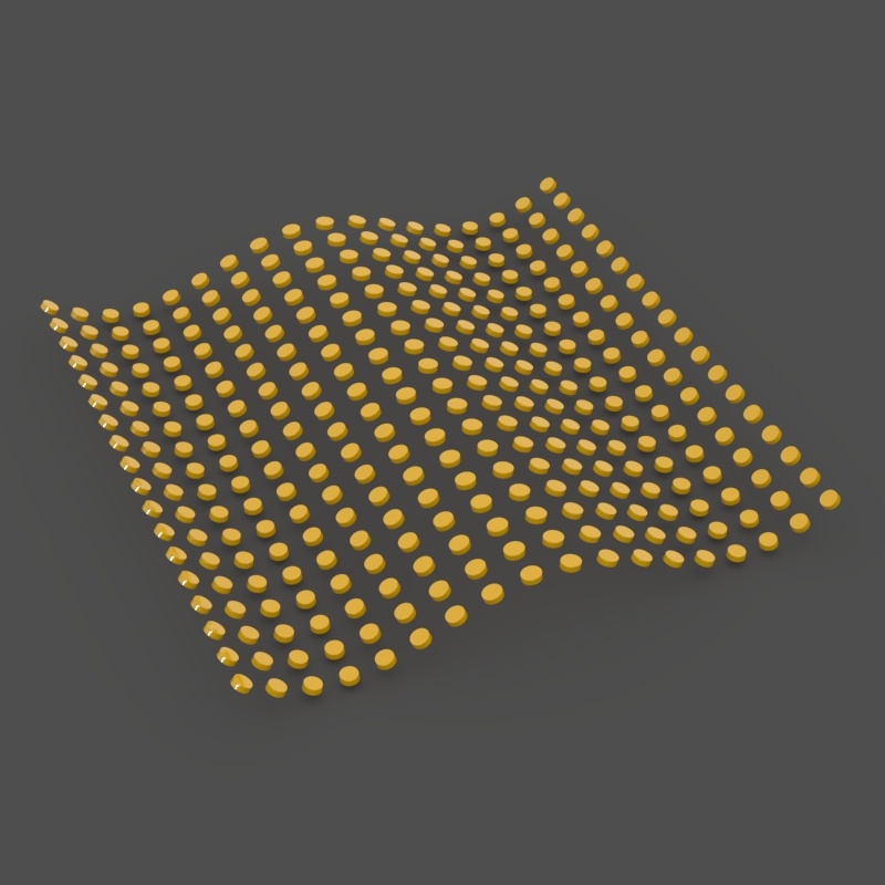
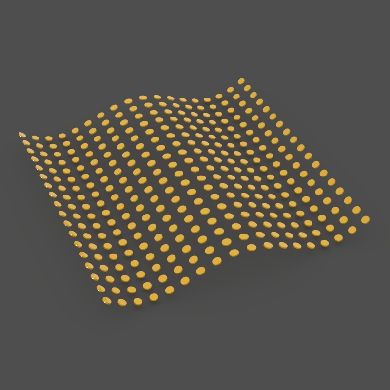
Subdivision Displacement
Below is an example of the difference between an original mesh and subdivision displacement. No displacement map is used. To smooth the image, the Amount parameter is set to 0. When the Amount parameter is set to above 0, V-Ray automatically loads a Noise map.
Original Mesh
Type = Subdivision, Amount = 0
Type = Subdivision , Amount > 0
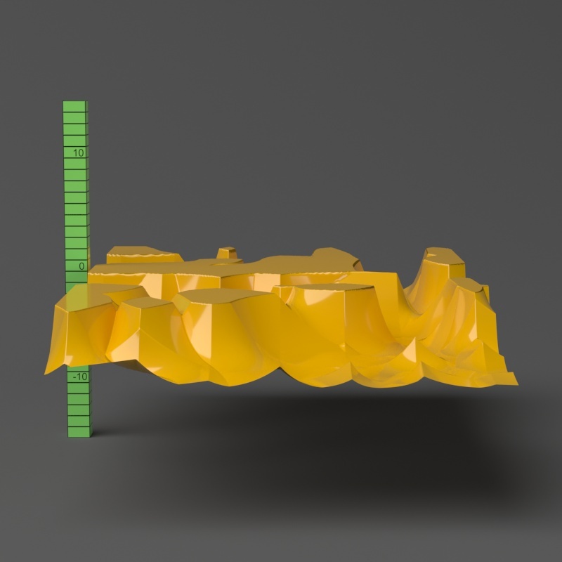
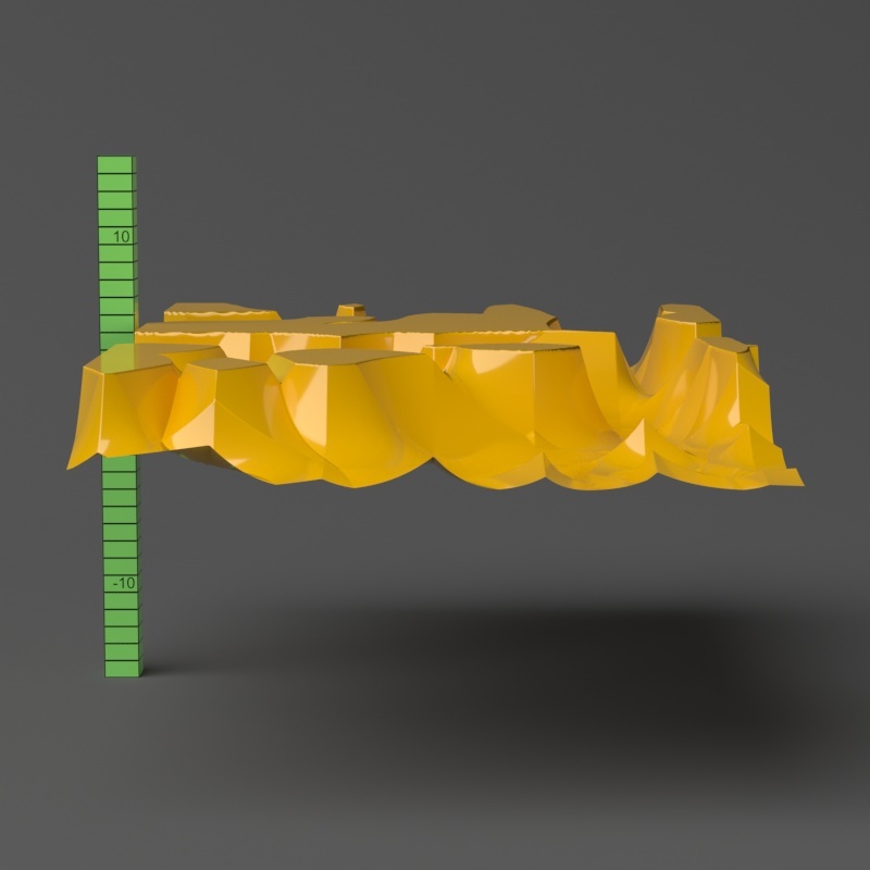
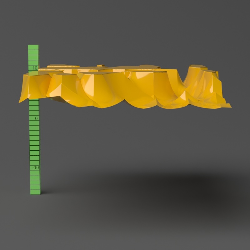
Shift
Note that the Shift parameter is an absolute value in world units. If you change the Amount, you will probably need to adjust the Shift too.
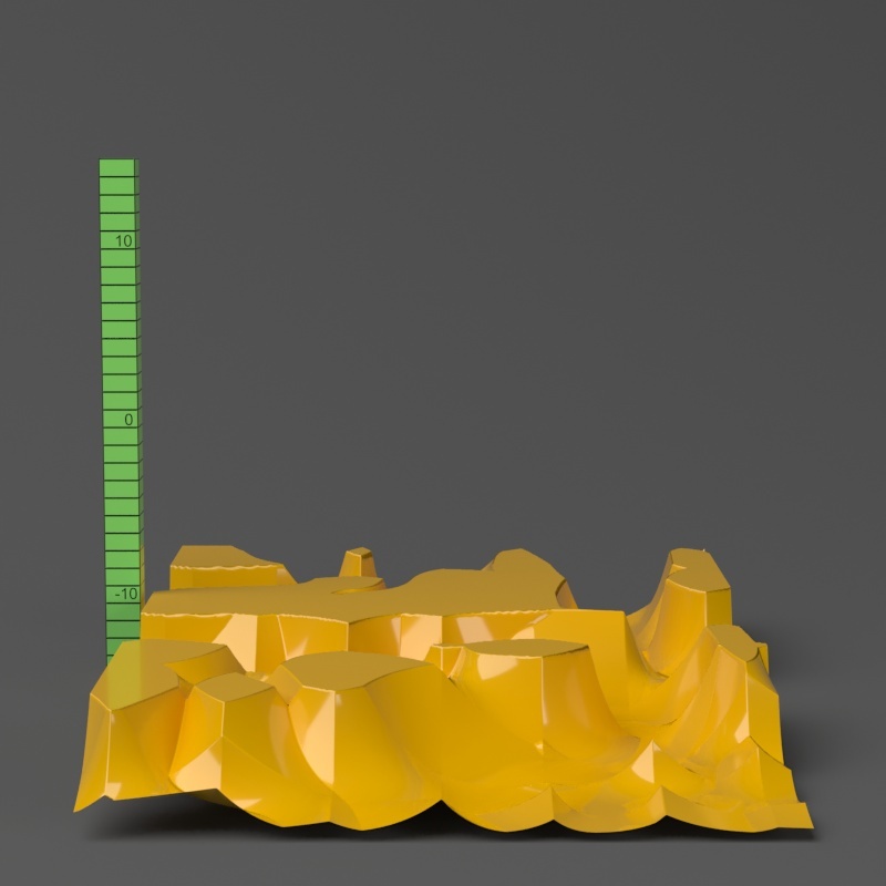
Shift = -10.0
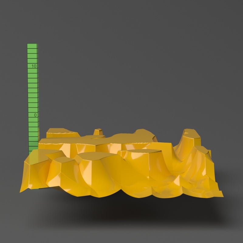
Shift = -5.0
Shift = 0.0
Shift = 5.0
Shift = 10.0
Clip Mapping
The Water level parameter is absolute in world units. For this example, Amount is set to 5.0 and Shift is set to 0.0. Note that when Water level reaches Amount + Shift, all geometry is clipped.
Water level = 0.0 (no clipping)
Water level = 1.25
Water level = 2.5
Water level = 3.75

Water level > 5.0 (all geometry is clipped)
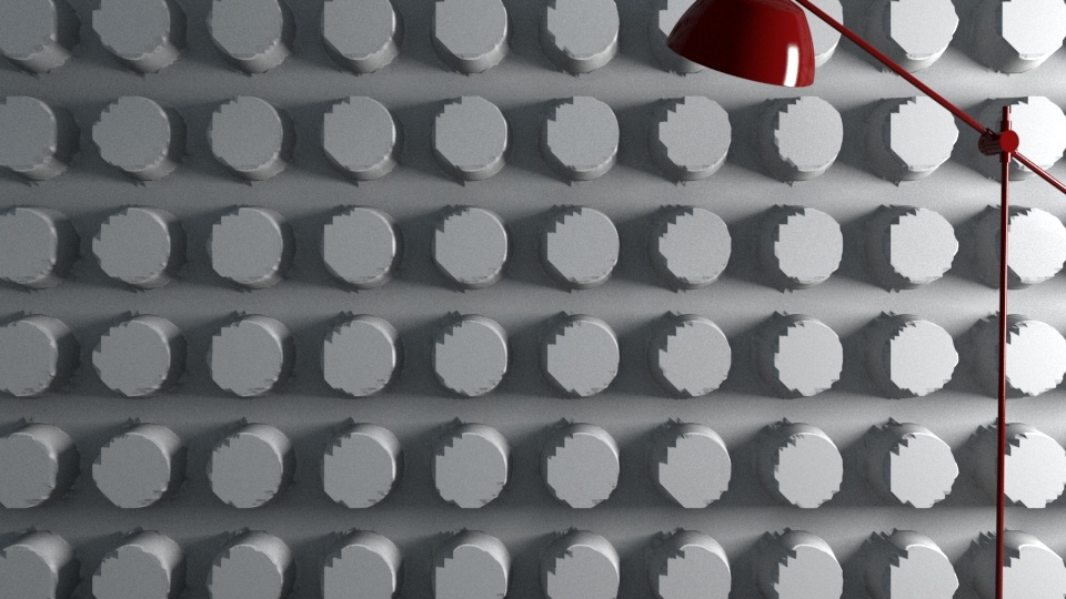
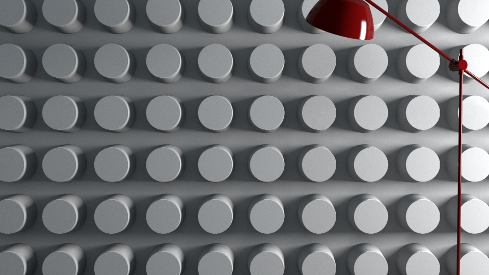
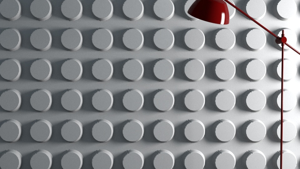
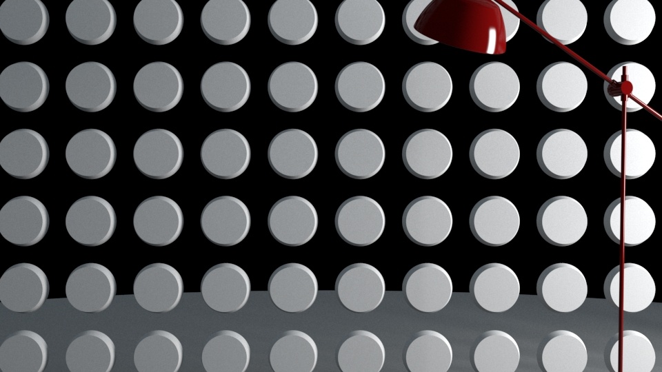
2D Mapping
This example demonstrates the use of displacement mapping to clip away geometry from an object. The displacement map is a Gradient Ramp with Radial Type. The Type used was 2D mapping (landscape).
Water level = 0/disabled
Water level = 0.25
Water level = 0.5
Water level = 0.75
Water level = 1

Water level > 1 (1.01)
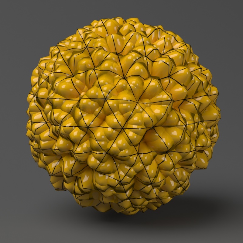
Edge Length
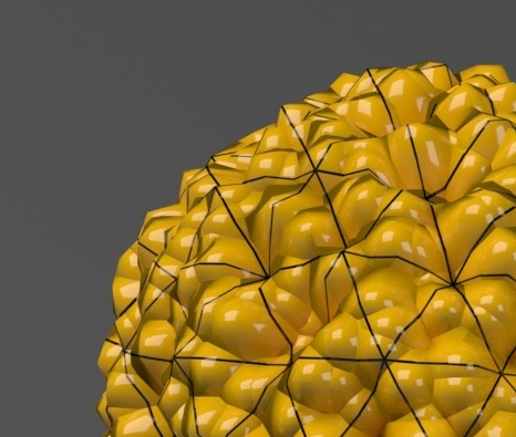
This example shows the effects of increasing the Edge length parameter. In this example View-dependent is enabled, so Edge length is expressed in pixels. In the examples, the closeup view is a blow-up rather than a zoomed view. This means that Edge length in the closeup view refers to pixels in the original image, not the blow-up rendering. Click the images for a larger view.
The image below was rendered with a VRayEdgesTex map in the Diffuse slot of the material to show the original triangles of the mesh. Additionally, we turned on the Faceted option in the VRayMtl. V-Ray not only smooths the surface normals, but also automatically applies a normals map that represents the normal of the perfect displaced surface, which makes the surface look a lot more detailed than it actually is.

Edge length = 0.5

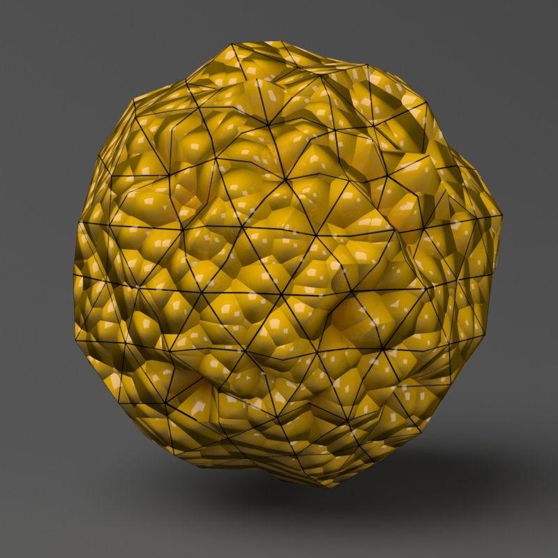
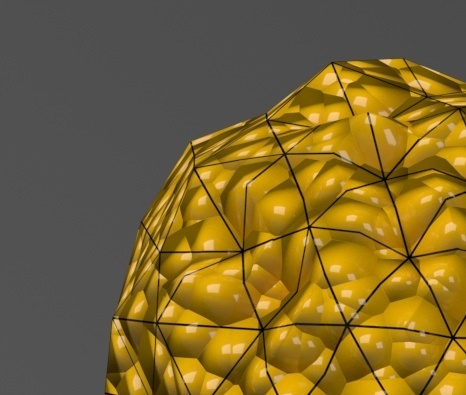
Edge length = 1.0

Edge length = 2.0
Edge length = 5.0
Edge length = 10.0
Vector Displacement
This example shows the effect of the vector_displacement (vector displacement) option in more detail.
The first image shows complex geometry on the left. This geometry was used to create a vector displacement map with the VRayVectorDisplBake utility. The second image shows the resulting displacement map, where the red, green and blue components define displacement vectors in the texture UVW space. The final imageshows the vector displacement map applied on another object through the VRayDisplacementMod modifier.
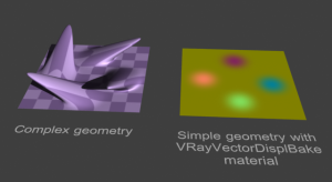 A piece of complex geometry, and a simple version
with a VRayVectorDisplBake material.
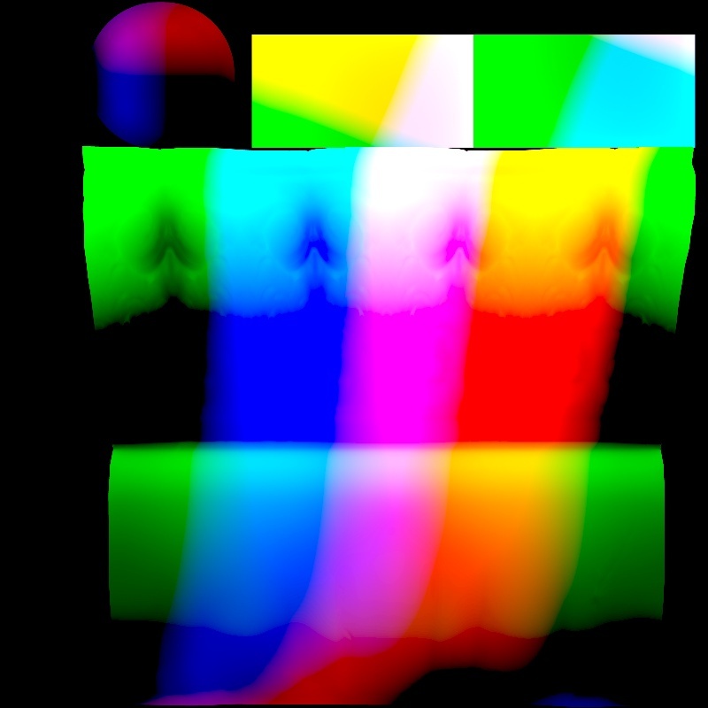
The displacement map, computed by texture baking with
the VRayCompleteMap element of the simple geometry.
The result is saved into an .exr file (a .png file is shown here).
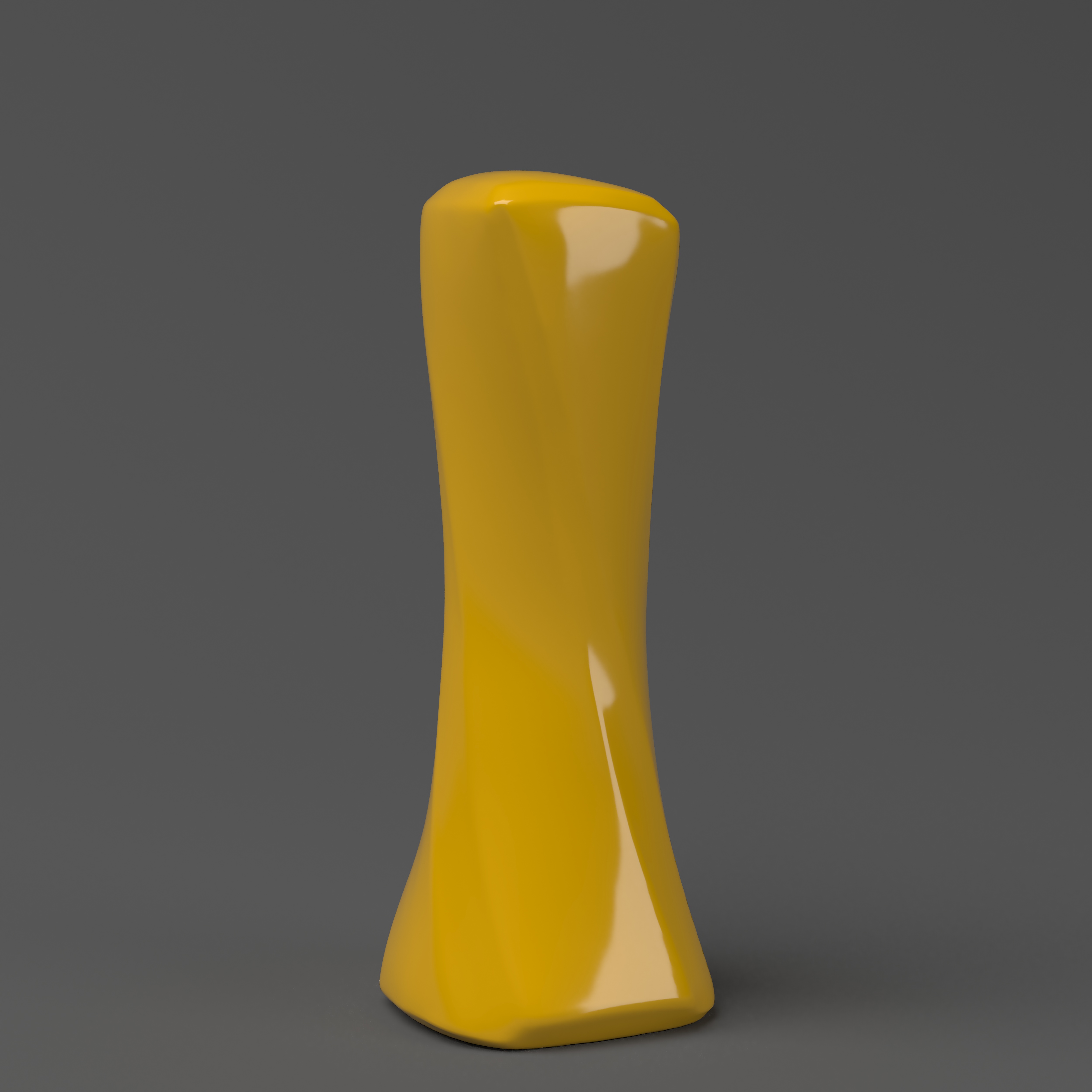
The displacement map applied on a different geometry through
the VRayDisplacementMod modifier with vector displacement.
Texture Boundaries
This example shows a plane mapped with a displacement map that has negative values. With the default boundaries for the displacement (from 0 to 1) we are unable to see the geometry displaced in the negative direction. However, once we set Texmap min and Texmap max to -1 and 1 respectively, we can see the displaced geometry in both the positive and negative direction.

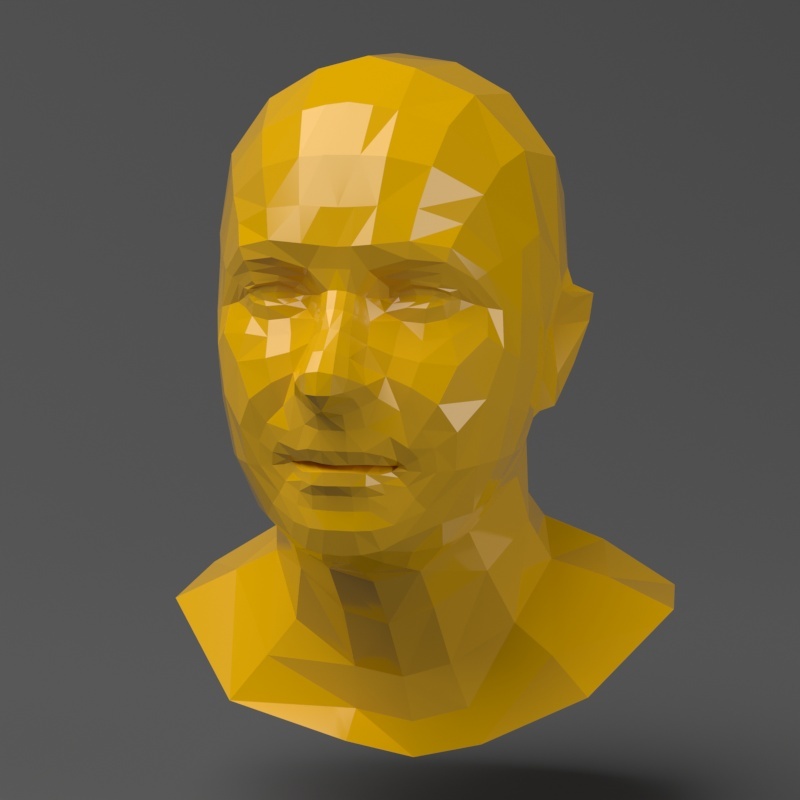
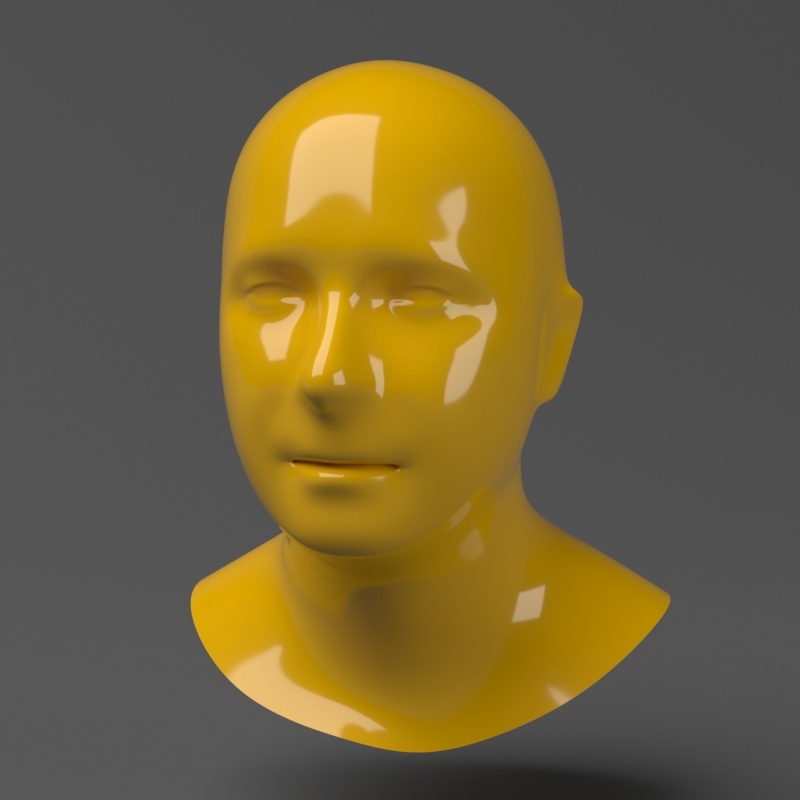
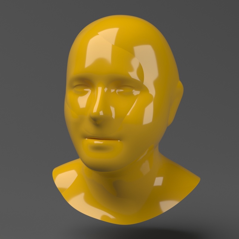
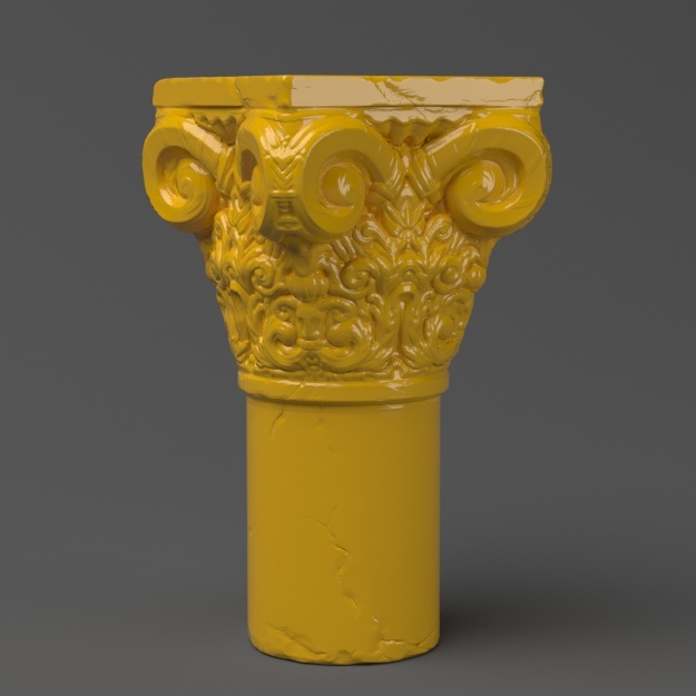
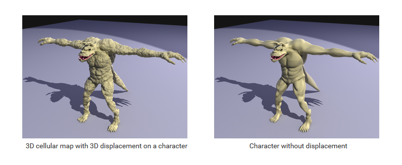
Displacement on a Character
This example shows displacement on a character mesh. The map is a 3D cellular map, so the 3D mapping displacement method is used.
Note that if the character is animated and the map is a 3D map using Object XYZ mapping, then the map will change relative to the object surface, since the surface itself changes its position in space. If you want to lock 3D procedural maps to the surfaces of animated objects, apply a UVW Map modifier with mode set to XYZ to UVW to the objects, and use Explicit mapping channel for the procedural map.
Code Example
# Compatibility with Python 2.7.
from __future__ import print_function

# The directory containing the vray shared object should be present in the PYTHONPATH environment variable.
# Try to import the vray module from VRAY_SDK/python, if it is not in PYTHONPATH
import sys, os
VRAY_SDK = os.environ.get('VRAY_SDK')
if VRAY_SDK:
    sys.path.append(os.path.join(VRAY_SDK, 'python'))
import vray

SCENE_PATH = os.path.join(os.environ.get('VRAY_SDK'), 'scenes')
# Change process working directory to SCENE_PATH in order to be able to load relative scene resources.
os.chdir(SCENE_PATH)

# Create an instance of VRayRenderer with default options. The renderer is automatically closed after the `with` block.
with vray.VRayRenderer() as renderer:
    # Register a simple log callback. Always useful for debugging.
    def dumpMsg(renderer, message, level, instant):
        if level == vray.LOGLEVEL_ERROR:
            print("[ERROR]", message)
        elif level == vray.LOGLEVEL_WARNING:
            print("[Warning]", message)
        elif level == vray.LOGLEVEL_INFO:
            print("[info]", message)
        # Uncomment for testing, but you might want to ignore these in real code
        #else: print("[debug]", message)
    renderer.setOnLogMessage(dumpMsg)

    # Load scene from a file.
    renderer.load(os.path.join(SCENE_PATH, 'texturing.vrscene'))

    bitmap = renderer.classes.BitmapBuffer()
    # Specify the file from which the bitmap will be loaded.
    bitmap.file = os.path.join('assets', 'Wood_Diff.jpg')
    # The Bitmap texture allows a bitmap image to be applied as a texture.
    texture = renderer.classes.TexBitmap()
    # Specify the bitmap image used as texture.
    texture.bitmap = bitmap

    # Create a GeomDisplacedMesh plugin
    displMesh = renderer.classes.GeomDisplacedMesh()
    # Assign a mesh and a displacement texture
    displMesh.mesh = renderer.plugins['Teapot_BodyShape@mesh1']
    displMesh.displacement_tex_color = texture
    # Increase displacement amount
    displMesh.displacement_amount = 3
    displMesh.use_globals = False
    # Apply the geometry to the existing node
    node = renderer.plugins['Teapot_BodyShape@node']
    node.geometry = displMesh

    # Start rendering.
    renderer.startSync()
    # Wait for rendering to end.
    renderer.waitForRenderEnd()
#define VRAY_RUNTIME_LOAD_PRIMARY
#include "vraysdk.hpp"
#include "vrayplugins.hpp"
#include "utils.h"

using namespace VRay;
using namespace VRay::Plugins;
using namespace std;

const char *BASE_PATH = getenv("VRAY_SDK");
string SCENE_PATH = (BASE_PATH ? string(BASE_PATH) : string(".")) + PATH_DELIMITER + "scenes";

int main() {
	// Change process working directory to SCENE_PATH in order to be able to load relative scene resources.
	changeCurrentDir(SCENE_PATH.c_str());
	// Load V-Ray SDK library.
	VRayInit init(NULL, true);

	// Create an instance of VRayRenderer with default options. The renderer is automatically closed at the end of the current scope.
	VRayRenderer renderer;
	// It's recommended to always have a console log
	renderer.setOnLogMessage(logMessage);

	// Load scene from a file.
	renderer.load("texturing.vrscene");

	BitmapBuffer bitmap = renderer.newPlugin<BitmapBuffer>();
	// Specify the file from which the bitmap will be loaded.
	bitmap.set_file("assets" PATH_DELIMITER "Wood_Diff.jpg");
	// The Bitmap texture allows a bitmap image to be applied as a texture.
	TexBitmap texture = renderer.newPlugin<TexBitmap>();
	// Specify the bitmap image used as texture.
	texture.set_bitmap(bitmap);

	// Create a GeomDisplacedMesh plugin
	GeomDisplacedMesh displMesh = renderer.newPlugin<GeomDisplacedMesh>();
	// Assign a mesh and a displacement texture
	displMesh.set_mesh(renderer.getPlugin("Teapot_BodyShape@mesh1"));
	displMesh.set_displacement_tex_color(texture);
	// Increase displacement amount
	displMesh.set_displacement_amount(3);
	displMesh.set_use_globals(false);
	// Apply the geometry to the existing node
	Node node = renderer.getPlugin<Node>("Teapot_BodyShape@node");
	node.set_geometry(displMesh);

	// Start rendering.
	renderer.startSync();
	// Wait for rendering to end.
	renderer.waitForRenderEnd();

	return 0;
}
using System;
using System.IO;
using VRay;
using VRay.Plugins;

namespace _displMesh
{
    class Program
    {
        static void Main(string[] args)
        {
            string SCENE_PATH = Path.Combine(Environment.GetEnvironmentVariable("VRAY_SDK"), "scenes");
            // Change process working directory to SCENE_PATH in order to be able to load relative scene resources.
            Directory.SetCurrentDirectory(SCENE_PATH);

            // Create an instance of VRayRenderer with default options. The renderer is automatically closed after the `using` block.
			using (VRayRenderer renderer = new VRayRenderer())
            {
                // Add a listener for any type of log message.
                renderer.LogMessage += new EventHandler<MessageEventArgs>((source, e) =>
                {
                    // You can remove the if for testing, but you might want to ignore Debug in real code
                    if (e.LogLevel != LogLevelType.Debug)
                    {
                        Console.WriteLine(String.Format("[{0}] {1}", e.LogLevel.ToString(), e.Message));
                    }
                });

                // Load scene from a file.
                renderer.Load("texturing.vrscene");

                BitmapBuffer bitmap = renderer.NewPlugin<BitmapBuffer>();
                // Specify the file from which the bitmap will be loaded.
                bitmap.File = Path.Combine("assets", "Wood_Diff.jpg");
                // The Bitmap texture allows a bitmap image to be applied as a texture.
                TexBitmap texture = renderer.NewPlugin<TexBitmap>();
                // Specify the bitmap image used as texture.
                texture.Bitmap = bitmap;

				// Create a GeomDisplacedMesh plugin
				GeomDisplacedMesh displMesh = renderer.NewPlugin<GeomDisplacedMesh>();
				// Assign a mesh and a displacement texture
				displMesh.Mesh = renderer.GetPlugin("Teapot_BodyShape@mesh1");
				displMesh.DisplacementTexColor = texture;
				// Increase displacement amount
				displMesh.DisplacementAmount = 3;
				displMesh.UseGlobals = false;
				// Apply the geometry to the existing node
				Node node = renderer.GetPlugin<Node>("Teapot_BodyShape@node");
				node.Geometry = displMesh;

                // Start rendering.
                renderer.StartSync();
                // Wait for rendering to end.
                renderer.WaitForRenderEnd();
            }
        }
    }
}
var path = require('path');
var vray = require(path.join(process.env.VRAY_SDK, 'node', 'vray'));

var SCENE_PATH = path.join(process.env.VRAY_SDK, 'scenes');
// Change process working directory to SCENE_PATH in order to be able to load relative scene resources.
process.chdir(SCENE_PATH);

// Create an instance of VRayRenderer with default options.
var renderer = vray.VRayRenderer();
// It's recommended to always have a console log callback
renderer.on("logMessage", function(message, level, instant) {
	if (level == vray.LOGLEVEL_ERROR)
		console.log("[ERROR] ", message);
	else if (level == vray.LOGLEVEL_WARNING)
		console.log("[Warning] ", message);
	else if (level == vray.LOGLEVEL_INFO)
		console.log("[info] ", message);
	// Uncomment for testing, but you might want to ignore these in real code
	//else console.log("[debug] ", message);
});

// Load scene from a file asynchronously.
renderer.load("texturing.vrscene", function(err) {
    if (err) throw err;

    var bitmap = renderer.classes.BitmapBuffer();
    // Specify the file from which the bitmap will be loaded.
    bitmap.file = path.join("assets", "Wood_Diff.jpg");
    // The Bitmap texture allows a bitmap image to be applied as a texture.
    var texture = renderer.classes.TexBitmap();
    // Specify the bitmap image used as texture.
    texture.bitmap = bitmap;

	// Create a GeomDisplacedMesh plugin
	var displMesh = renderer.classes.GeomDisplacedMesh();
	// Assign a mesh and a displacement texture
	displMesh.mesh = renderer.plugins["Teapot_BodyShape@mesh1"];
	displMesh.displacement_tex_color = texture;
	// Increase displacement amount
	displMesh.displacement_amount = 3;
	displMesh.use_globals = false;
	// Apply the geometry to the existing node
	var node = renderer.plugins["Teapot_BodyShape@node"];
	node.geometry = displMesh;

    // Start rendering.
    renderer.start(function(err) {
        if (err) throw err;
        // Wait for rendering to end.
        renderer.waitForRenderEnd(function() {
            renderer.close();
        });
    });
});
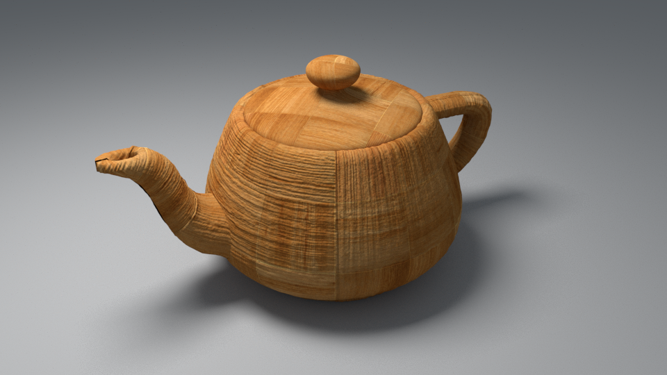
Result
Notes
- Textures are applied to the displaced surface rather than the original surface. This means that textures with Object XYZ and World XYZ mapping might look different on the displaced object, compared to how they look on the original undisplaced one. If this is not desired (e.g. you want the displacement map to match the texture), use explicit channel mapping for the material textures and use the Object XYZ/World XYZ mapping for displacement maps only.
- Displaced objects will not work properly with standard shadow maps. The shadow maps will include information about the undisplaced mesh. For small displacement amounts, this might work fine. Note that displaced objects cast accurate shadows with Shadow Map shadows.
- GeomDisplacedMesh has no effect on GeomInfinitePlane objects, Proxy nodes or GeomHair objects.
- The 2D mapping (landscape) method will ignore the Tiling parameters specified in the textures themselves; as a side effect this means that it will not work with the Real-world map size options in the Bitmap and other textures. Instead, you must modify the UVW coordinates of the object, or use the 3D mapping method.
- The 2D mapping (landscape) method only supports one UV mapping channel.