The Source controls the emission of fluid and where the fluid emits from, so that the simulator knows where in 3D space the fluid can be born.
An Emitter can be geometry and/or particles, and is what actually emits the fluid inside the simulation grid. The emitter(s) must be selected by the Source in order to emit fluid inside the simulator, unless you are using the Initial fill option in the simulator’s settings, or specifying a geometry to do an initial fill with liquid.
The Source also contains its own settings that determine how much fluid is emitted, what is emitted, and so forth. A Liquid Source can be used to emit fluid into a Liquid Simulatorusing Liquid FLIP particles, or any of the Source's Grid Channel options, and it can also emit fluid for multiple channels at once.
This includes emitting options such as RGB color and Viscosity, as well as emitting secondary particle types like Splashes, Mist and Foam.
UI Text Box
type
info
If you have many Simulators in the scene, by default each Simulator will interact with a Source's Emitter Nodes, as long as they are inside that Simulator. You can exclude Sources or Emitters from a Simulator's Scene Interaction rollout.
If you switch to use the Include List mode, you have to pick both the Source and its Emitter Nodes in the Interaction List.
The Source can emit in three different Emit Modes:
Surface Force creates fluid only at the surface of emitters
Volume Brush fills the entire volume of emitters
Volume Inject fills an emitter’s volume while adding pressure for an explosive effect
You can also use textures as masks for each of the emission channels, to create more interesting emission behaviors, with more variation. Specifically, Masks make it possible to emit unevenly from only some areas, or emit unevenly from the entire volume of an emitter.
UI Text Box
type
tip
Using textures as masks can help to break up the emission, and can lead to a more varied or natural looking result.
For example, you could use a black and white noise texture as a Mask when emitting Liquid particles, to make it so that the black parts of the texture emit nothing, while the white parts emit Liquid.
Additionally, each channel can have one or many Discharge Modifiers. They can give you more precise procedural control over how the fluid gets emitted.
Discharge modifiers vary the emission over different parts of the emitter, depending on the properties of the emitter - e.g. the direction of its Normals, the speed of movement at each point of an animated emitter, etc
Column
width
50%
...
Section
Column
width
50%
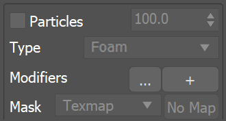
Particles | particles, useprt – Allows the source to emit particles into the Simulator. The particle birth rate is in thousands of particles per second.
Type | prttype – Specifies the type of particles created by this source:
Foam – The source will emit Foam particles. Note that Foam simulation must be enabled from the Simulator so this type of particles can be emitted into it. Splashes – The source will emit Splash particles. Note that Splash simulation must be enabled from the Simulator so this type of particles can be emitted into it. Mist– The source will emit Mist particles. Note that Splash | Mist simulation must be enabled from the Simulator so this type of particles can be emitted into it.
Modifiers | dmodprt – A Discharge Modifier can be attached here in order to affect the Particles parameter.
Mask | prtmap, useprtmap – Allows you to vary the amount of particles over the surface or the volume of the emitters. If this is not used, the Source will emit equal amount of particles over the entire surface or volume of the emitters.
Column
width
5%
Column
width
45%
...
Emission
...
Section
Column
width
50%
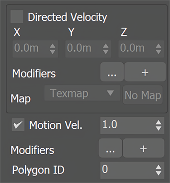
Direct Velocity | useDirectedVelocity – Creates velocities in a certain direction or based on a Texmap.
Modifiers | dmoddirvel– Discharge Modifiers can be attached here in order to affect the Direct Velocity parameter.
Map | usedirvelmap – Allows you to vary the Direct Velocity over the surface or the volume of the emitters. If this is not used, the Source will emit equal Direct Velocity over the entire surface or volume of the emitters.
None – The Direct Velocity channel will not vary. Texmap – Allows you to specify a texture map to direct the velocity of the fluid emitted by the Source. When using Texmap, the Direct Velocity is generated from the selected texture and is not multiplied by the value added in the Directed Velocity X/Y/Z slots. Vertex Color – The Direct Velocity of the emitted fluid is determined by the emitter node's vertex colors. When using Vertex Color, the Direct Velocity is generated from the created vertex color and is not multiplied by the value added in the Directed Velocity X/Y/Z slots.
Anchor
Velocity
Velocity
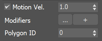
Motion Vel. | usevel, velmult – When enabled, moving emitters will affect the velocity of the fluid and make it follow the emitter. This effect is controlled with the specified multiplier. If the emitter is not moving, this option has no effect.
UI Text Box
type
note
Particles with attached geometry (such as PFlow particles using a Shape Instance operator) will act like standard geometry obstacles and will push the fluid by default, as long as their Solid Phoenix property is enabled.
Particles without geometry (even PFlow particles with a plain Shape operator) will need to be attached to a Source in order to interact with the fluid in any way.
Particles without geometry can emit fluid using their shape and size using the Source's Particle Shape and Custom Prt Size options.
Particles without geometry will not affect the fluid's motion by default, so you need to enable Motion Vel. explicitly if you need this effect.
If Motion Vel. is enabled, the fluid emitted by a particle may refuse to leave the particle shape area and continue to move together with the particle, because it will have the same velocity.
Modifiers | dmodvel– Discharge Modifiers can be attached here in order to affect the Motion Vel. parameter.
Polygon ID | poly_id – Only the polygons with the specified ID of the emitter geometry will emit the fluid.
Column
width
5%
Column
width
45%
Image RemovedImage Added
Texture UVW
...
Section
Column
width
50%
UI Text Box
type
info
The main purpose of Texture UVW is to provide dynamic UVW coordinates for texture mapping that follow the simulation. If such simulated texture coordinates are not present for mapping, textures assigned to your simulation will appear static, with the simulated content moving through the image. This undesired behavior is often referred to as 'texture swimming'. In Phoenix such textures can be used for mapping the fire or smoke color and opacity of volumetrics, as well as the color and opacity of meshes. Texture can be also used for displacing volumetrics and meshes.
UVW coordinates are generated by simulating an additional Texture UVW Grid Channel which has to be enabled under theOutput rollout for the settings below to have any effect.
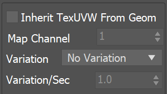
Inherit TexUVW From Geom | texuvw_geom – Sets the UVW Grid Channel value for each cell where fluid is emitted to the UV value of the emission geometry in that cell. As a consequence, for example, modulating the Smoke Color with a texture on the very first frame will produce a render that looks very close to the original geometry, if the same texture was applied to it. When this option is disabled, the TexUVW values will be based on the position of the emission object inside the Simulator. Please check the Texture UVW example below.
Map Channel | texuvw_geom_ch – Specifies the Map Channel index to sample. This is useful when your geometry has multiple UV sets (called Map Channels in 3ds Max) with different layouts.
Variation | texuvw_var_mode – Variation is used to offset the UVW coordinates upon emission to avoid visible tiling once a texture is applied to the resulting simulation. Similarly to a printer, if the UVW channel is not varied, it would be like printing out the same sentence over and over again on each new line. When varied, the printer will change the line being printed. The following methods are available:
No Variation - The emitted TexUVW will not change over time.
Along U/V/W - The emitted TexUVW value will change over time in the U/V/W direction and by the amount set in Variation/Sec.
Along Grid/Object/World Normals - The emitted TexUVW value will change over time in the direction of the emitting geometry's normals in Grid/Object/World space and by the amount set in Variation/Sec. Grid space is the system of the Simulator, it always has the Z axis pointing up. Object space is the local transform of the emitter.
Variation/Sec | texuvw_var_speed – Controls the variation speed - the default value of 1 will cause textures assigned for rendering to repeat exactly once for every 30 frames (1 second) of the simulation.
Column
width
5%
Column
width
45%
...
Section
Example: Inherit TexUVW with Variation
UI Text Box
type
info
The following video provides examples of InheritedTexture UVW coordinates repeating along the V-axis over 0, 1 and 2 seconds. When Variation is set to 0, the V coordinate remains static. If Variation is set to 1, it takes one second for a full repetition/tile along the V-axis.