![]()
Page History
Overview
...
| Section | |||||||||||||||||||||
|---|---|---|---|---|---|---|---|---|---|---|---|---|---|---|---|---|---|---|---|---|---|
|
| UI Expand | ||
|---|---|---|
| ||
|
Parameters
Emitter Nodes
| Section | ||||||||||||||||||||||
|---|---|---|---|---|---|---|---|---|---|---|---|---|---|---|---|---|---|---|---|---|---|---|
|
General
|
| UI Expand | ||
|---|---|---|
| ||
|
Parameters
...
Emitter Nodes
...
| UI Text Box | ||
|---|---|---|
| ||
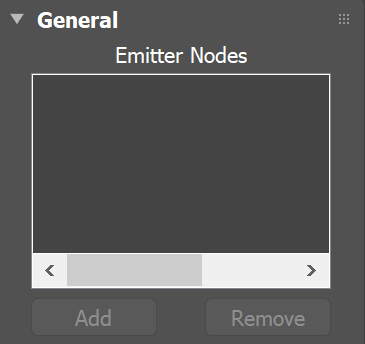
Non-Phoenix particles, such as Particle Flow or tyFlow particles, can also act as emitters for a Phoenix Source. They can emit from a spherical 3D shape, or from instanced geometry. |
| UI Text Box | ||
|---|---|---|
| ||
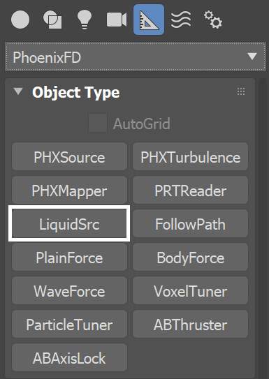
Note that the Source icon itself does not emit fluid, so the position of the icon's viewport gizmo in the scene does not matter. Instead, you must pick the geometry and/or particles that you want to use as emitters, in the Source’s Emitter Nodes list. |
| Section | ||||||||||||||||||||||
|---|---|---|---|---|---|---|---|---|---|---|---|---|---|---|---|---|---|---|---|---|---|---|
|
General
...
| UI Text Box | ||
|---|---|---|
| ||
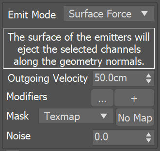
Fluid can be emitted from a geometry’s surface, or from the entire volume of an emitting geometry. Note that if the Emit Mode is set to Volume Brush or Volume Inject, and you have a Texture Mask using either Explicit Map Channel or Vertex Color Channel mapping, then the Mask will be applied on the whole volume, based on the closest geometry surface. |
| UI Text Box | ||
|---|---|---|
| ||
Even if you do not simulate visible fluid like liquid, there can still be Velocity simulated within the grid, if for example, you animate an object to move around inside the grid to stir the Velocity channel. The simulated velocity can also be previewed in the viewport, or even rendered. |
| Section | ||||||||||||||||||||||||||
|---|---|---|---|---|---|---|---|---|---|---|---|---|---|---|---|---|---|---|---|---|---|---|---|---|---|---|
|
...
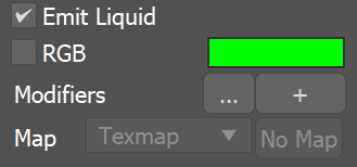
Liquid & RGB
...
| Section | ||||||||||||||||||||
|---|---|---|---|---|---|---|---|---|---|---|---|---|---|---|---|---|---|---|---|---|
|
...
| Section | |||||||||||||||||
|---|---|---|---|---|---|---|---|---|---|---|---|---|---|---|---|---|---|
Example: Inherit TexUVW with Variation
|
...