![]()
Page History
Overview
...
| Div | ||||
|---|---|---|---|---|
| ||||
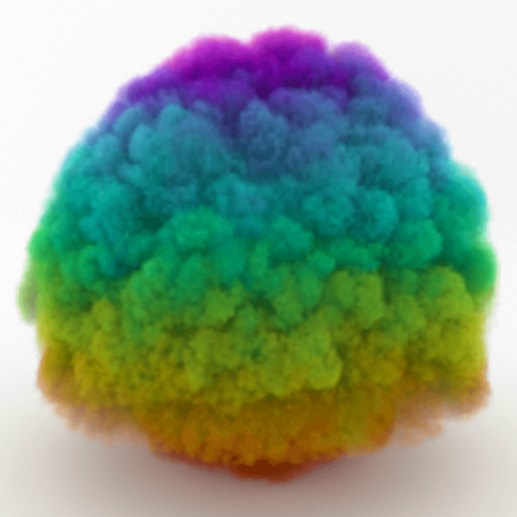
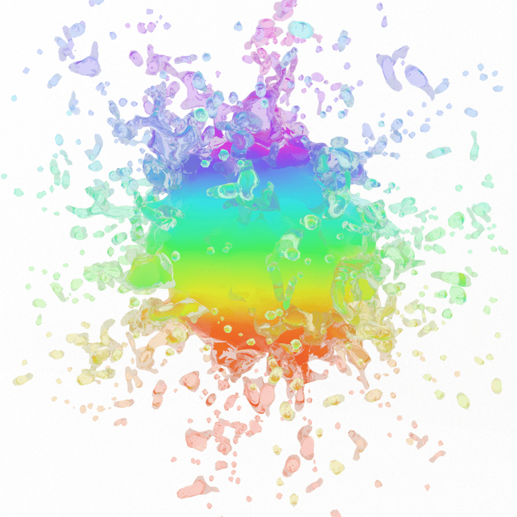
You can use the Fire Source to emit fire and smoke into Fire/Smoke Simulators. It's not a problem to use it for emitting liquid as well, but you have to understand Grid Channel ranges well. You can emit fluid from geometry or from particles. The fluid can be emitted from the surface, or from the entire volume of emitting geometry. Particles can emit from a spherical shape, or from instanced geometry shapes. Note that the viewport gizmo of the Source does not emit fluid itself - you have to first pick the geometry or particles you would use as emitters in the Source's list. The position of the Source icon in the scene does not matter. If you have many Simulators in the scene, by default each Simulator will interact with a Source's Emitter Nodes as long as they are inside this Simulator. You can exclude Sources or Emitters from a Simulator's Scene Interaction rollout. If you use Include mode, you have to pick both the Source and its Emitter Nodes in the Interaction List. The Source can emit in 3 different Emit Modes - Surface Force mode creates fluid only at the surface of emitters, Volume Brush fills the entire volume of the emitters, and Volume Inject also fills the emitter's volume and adds pressure for an explosive effect. You can emit any fluid grid channel and you can emit many channels at once. Additionally, you can emit particles from the Source. If you want to emit unevenly only from some areas or volumes of the emitters, you can use a Mask for each of the emission channels. Also Also, note that if Emit Mode is set to Volume Brush or Volume Inject, the Mask cannot use Inject and the Mask uses Explicit Map Channel or Vertex Color Channel mapping, because these apply only for the surface of the geometrythen the Mask will be applied on the whole volume, based on the closest geometry surface. Additionally, each channel can have one or many Discharge Modifiers. They allow you to gain more precise procedural control over how the fluid gets emitted. Discharge modifiers vary the emission over different parts of the emitter depending on properties of the emitter - e.g. the direction of its normals, the speed of movement at each point of an animated emitter, etc. |
...
| Div | ||||
|---|---|---|---|---|
| ||||
Emitter Nodes | sources – Specifies a list of objects that will emit fluid. Both geometry and particle systems can be selected here. Press the Add button and pick an object from the Viewport, or a list of objects using the Scene Explorer. |
General
...
| Anchor | ||||
|---|---|---|---|---|
|
...
Noise | noise – Varies the Outgoing Velocity, Inject Power and Brush Effect (%) across the surface or the volume of the emitting geometry or particle. The variation also changes over time. This is a shorthand for using an animated noise in the Mask slot.
Emitted Channels
...
...
| Div | ||||
|---|---|---|---|---|
| ||||
Temperature | temperature, uset – Specifies the temperature of the emitted fluid, in Kelvin. A value of 0 is absolute zero, and a value of 300 denotes room temperature. Temperature above 300 makes the fluid rise up, while temperature below 300 makes it fall down. You can find out more about Phoenix Grid Channel Ranges here. If the Temperature channel is not enabled in the Output rollout of the Simulator, this parameter will be ignored. Modifiers | dmodt – Discharge Modifiers can be attached here in order to affect the Temperature parameter. Mask | tmap, usetmap – Allows you to vary the channel over the surface or the volume of the emitters. If this is not used, the Source will emit equal temperature over the entire surface or volume of the emitters. |
...
| Div | |||||||
|---|---|---|---|---|---|---|---|
| |||||||
RGB | uvw, useuvw – If the RGB Map is not enabled, the emitted fluid's RGB channel will contain the specified color. If the RGB Map is enabled, the RGB values from the texture map will be used instead of the color swatch. If the RGB channel is not enabled in the Output rollout of the Simulator, this parameter will be ignored. AlsoAlso, note that if Emit Mode is set to Volume Brush or Volume Inject, Inject and the Map cannot use uses Explicit Map Channel or Vertex Color Channel mapping, because these apply only for the surface of the geometry then the Map will be applied on the whole volume, based on the closest geometry surface. Modifiers | dmodrgb – Discharge Modifiers can be attached here in order to affect the RGB parameter. Map | uvwmap, useuvwmap – Allows you to vary the RGB over the surface or the volume of the emitters. If this is not used, the Source will emit equal RGB over the entire surface or volume of the emitters. None – The RGB channel will not vary.
|
...
Polygon ID | poly_id – Only the polygons with the specified ID of the emitter geometry will emit the fluid. This option affects the discharge only in Surface Force mode.
| Anchor | ||||
|---|---|---|---|---|
|
...
| UI Text Box | ||||
|---|---|---|---|---|
| ||||
The main purpose of Texture UVW is to provide dynamic UVW coordinates for texture mapping that follow the simulation. If such simulated texture coordinates are not present for mapping, textures assigned to your simulation will appear static, with the simulated content moving through the image. This undesired behavior is often referred to as 'texture swimming'. In Phoenix such textures can be used for mapping the fire or smoke color and opacity of volumetrics, as well as the color and opacity of meshes. Texture can be also used for displacing volumetrics and meshes. UVW coordinates are generated by simulating an additional Texture UVW Grid Channel which has to be enabled under the Output rollout for the settings below to have any effect. For additional information on the Texture UVW feature, please check the Dynamics roll-out rollout documentation. |
Inherit TexUVW From Geom | texuvw_geom – Sets the UVW Grid Channel value for each cell where fluid is emitted to the UV value of the emission geometry in that cell. As a consequence, for example, modulating the Smoke Color with a texture on the very first frame will produce a render that looks very close to the original geometry, if the same texture was applied to it. When this option is disabled, the TexUVW values will be based on the position of the emission object inside the Simulator. Please check the Texture UVW example below.
...
- No Variation - The emitted TexUVW will not change over time.
- Along U/V/W - The emitted TexUVW value will change over time in the U/V/W direction and by the amount set in Variation/Sec.
- Along Grid/Object/World Normals - The emitted TexUVW value will change over time in the direction of the emitting geometry's normals in Grid/Object/World space and by the amount set in Variation/Sec. Grid space is the system of the Simulator, it always has the Z axis pointing up. Object space is the local transform of the emitter.
Variation/Sec | texuvw_var_speed – Controls the variation speed - the default value of 1 will cause textures assigned for rendering to repeat exactly once for every 30 frames (1 second) of the simulation.
Emission from Particles
...
Time Base | timebase – This parameter is used when emitting from particle systems. It allows you to animate the parameters using the age of the particle instead of the timeline frame time:
...
Example: RGB Map Vertex Color
...
| Section | ||||||||||||||||||||||
|---|---|---|---|---|---|---|---|---|---|---|---|---|---|---|---|---|---|---|---|---|---|---|
|