![]()
Page History
...
| Section | |||||||||||||||||||
|---|---|---|---|---|---|---|---|---|---|---|---|---|---|---|---|---|---|---|---|
|
...
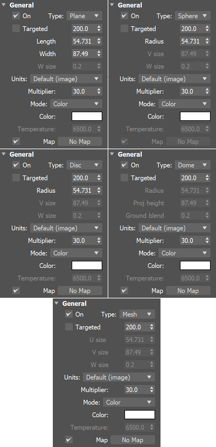
General Rollout
...
| Section | ||||||||||||||||||||||||||||
|---|---|---|---|---|---|---|---|---|---|---|---|---|---|---|---|---|---|---|---|---|---|---|---|---|---|---|---|---|
|
...
| Section | |||||||||||||||||||||||||||||||
|---|---|---|---|---|---|---|---|---|---|---|---|---|---|---|---|---|---|---|---|---|---|---|---|---|---|---|---|---|---|---|---|
|
...
...
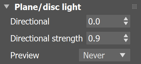
Rectangle/Disc Light Rollout
...
| Section | |||||||||||||||
|---|---|---|---|---|---|---|---|---|---|---|---|---|---|---|---|
|
...
| Section | |||||||||||||||||||||||||||||||||||||
|---|---|---|---|---|---|---|---|---|---|---|---|---|---|---|---|---|---|---|---|---|---|---|---|---|---|---|---|---|---|---|---|---|---|---|---|---|---|
|
...
| Anchor | ||||
|---|---|---|---|---|
|
...
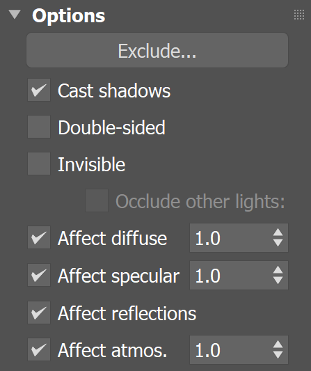
Options Rollout
...
| Section | |||||||||||||||
|---|---|---|---|---|---|---|---|---|---|---|---|---|---|---|---|
|

| Anchor | ||||
|---|---|---|---|---|
|
...
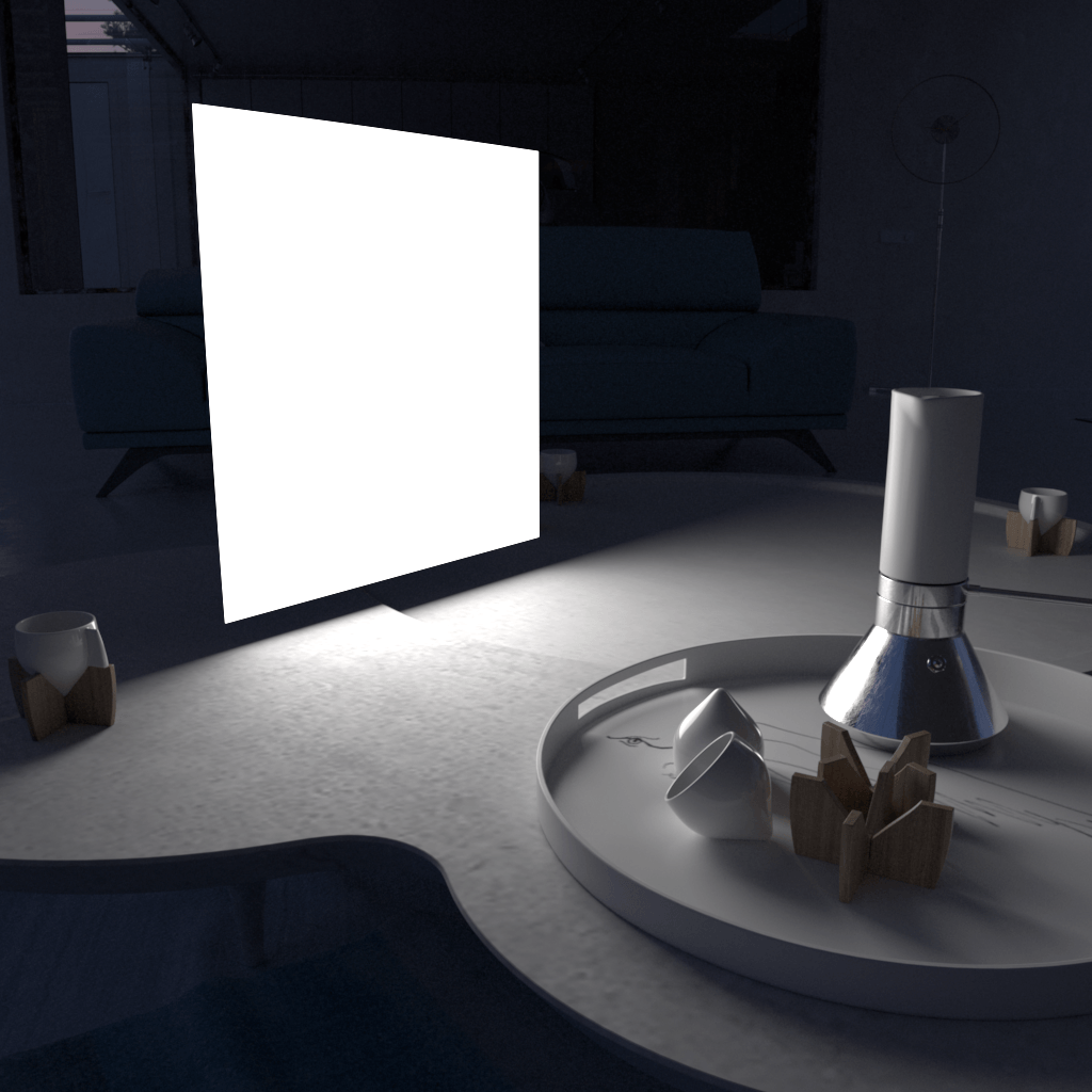
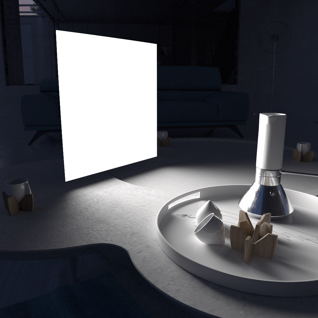
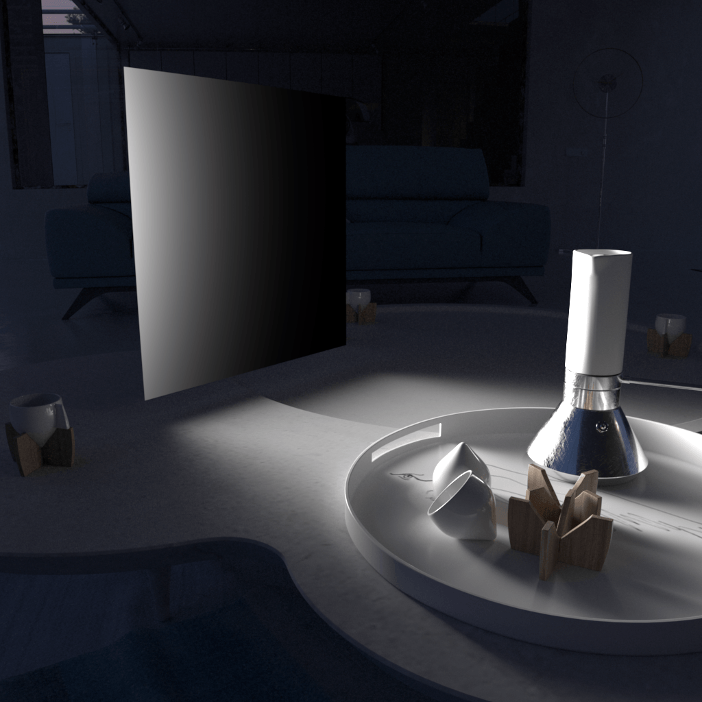
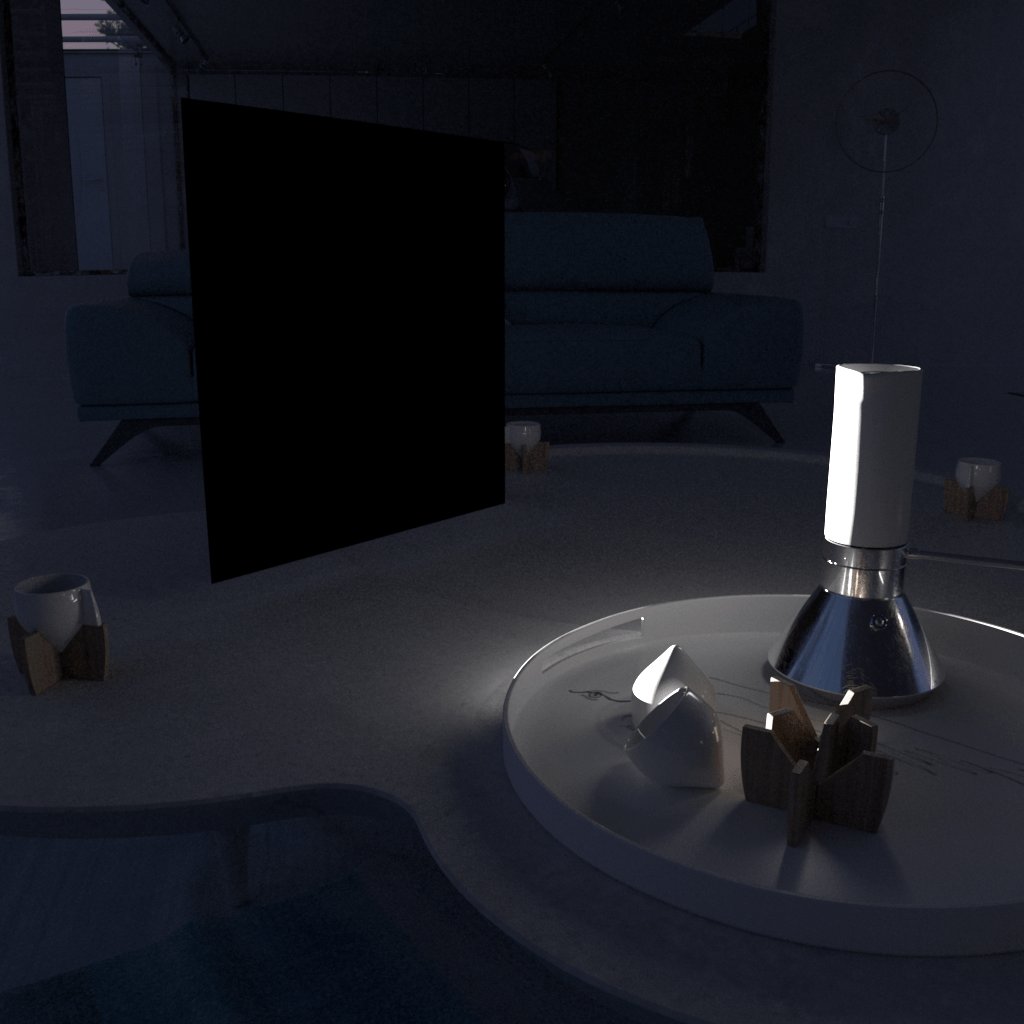
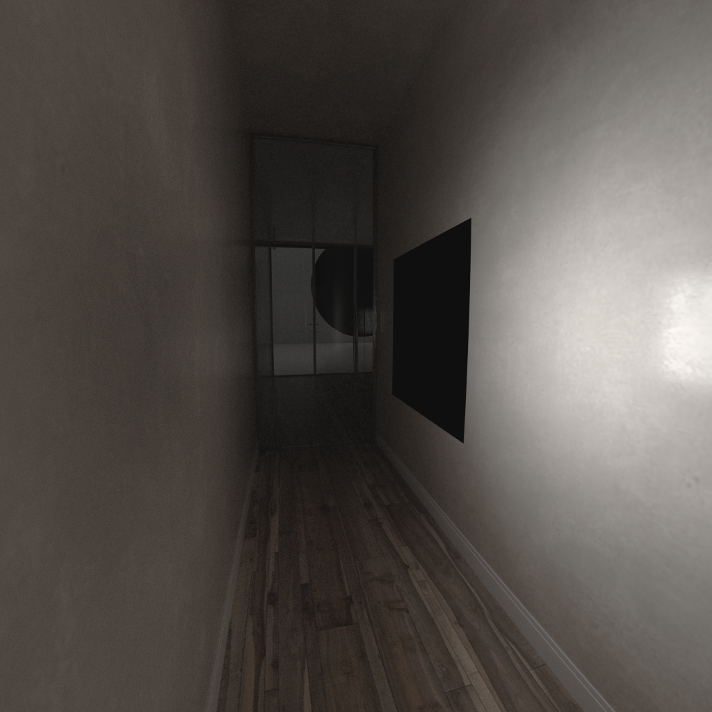
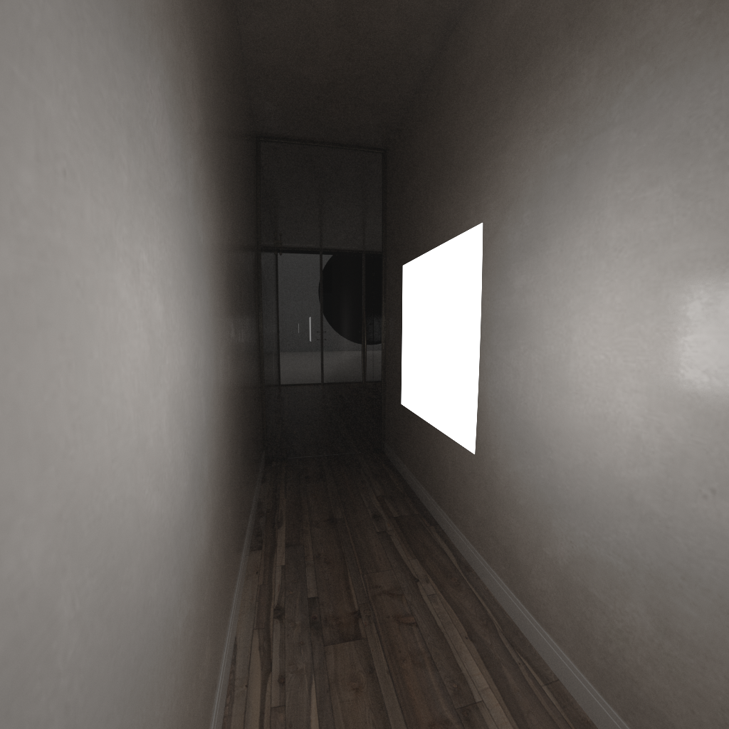
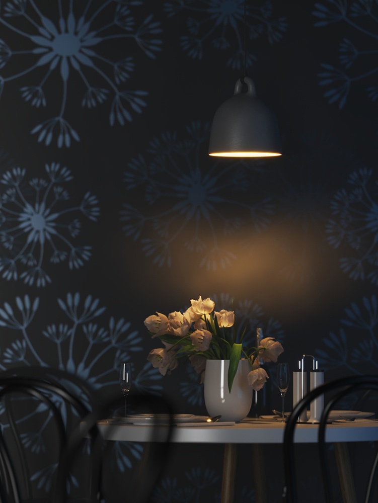
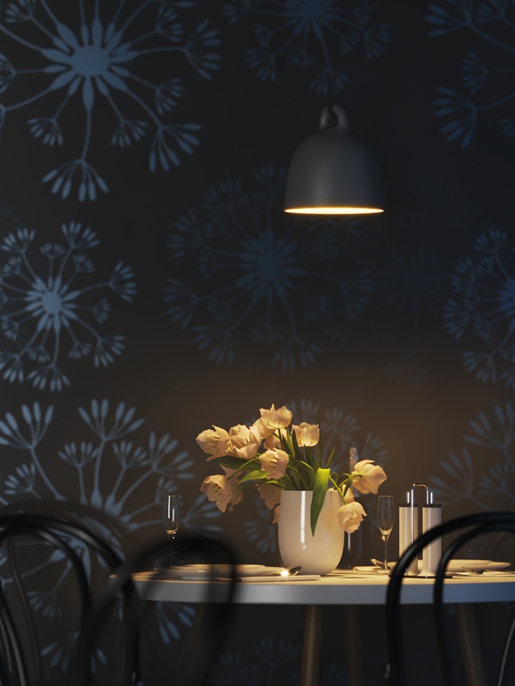
Example: Single-Sided vs Double-Sided Lights
...
| Section | |||||||||||||||||||||||||||||||
|---|---|---|---|---|---|---|---|---|---|---|---|---|---|---|---|---|---|---|---|---|---|---|---|---|---|---|---|---|---|---|---|
|
...
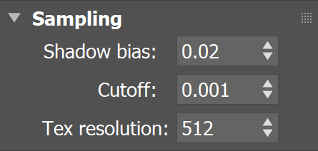
Sampling Rollout
...
| Section | |||||||||||||||
|---|---|---|---|---|---|---|---|---|---|---|---|---|---|---|---|
|
...
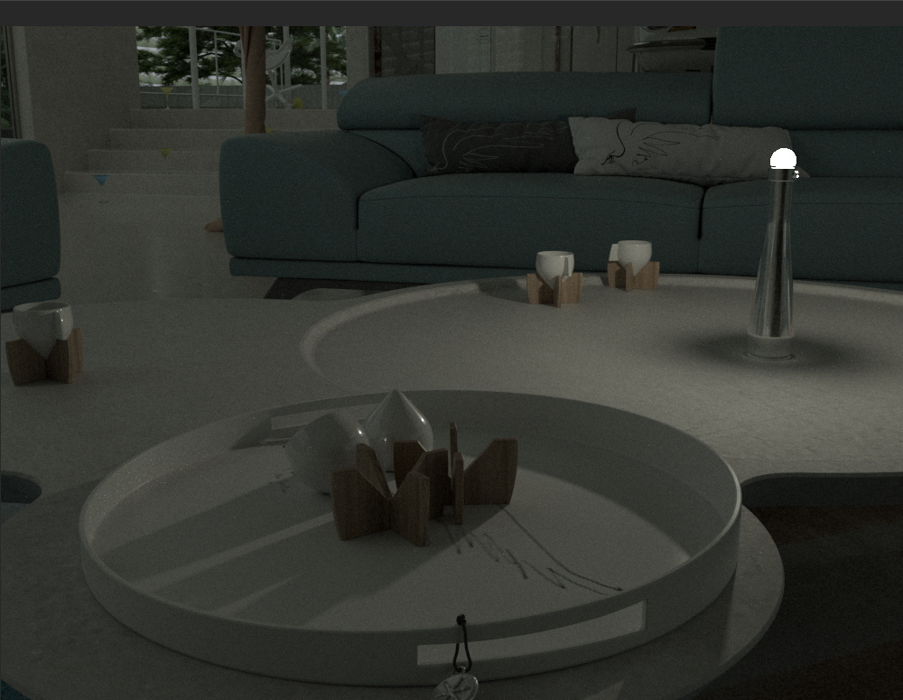
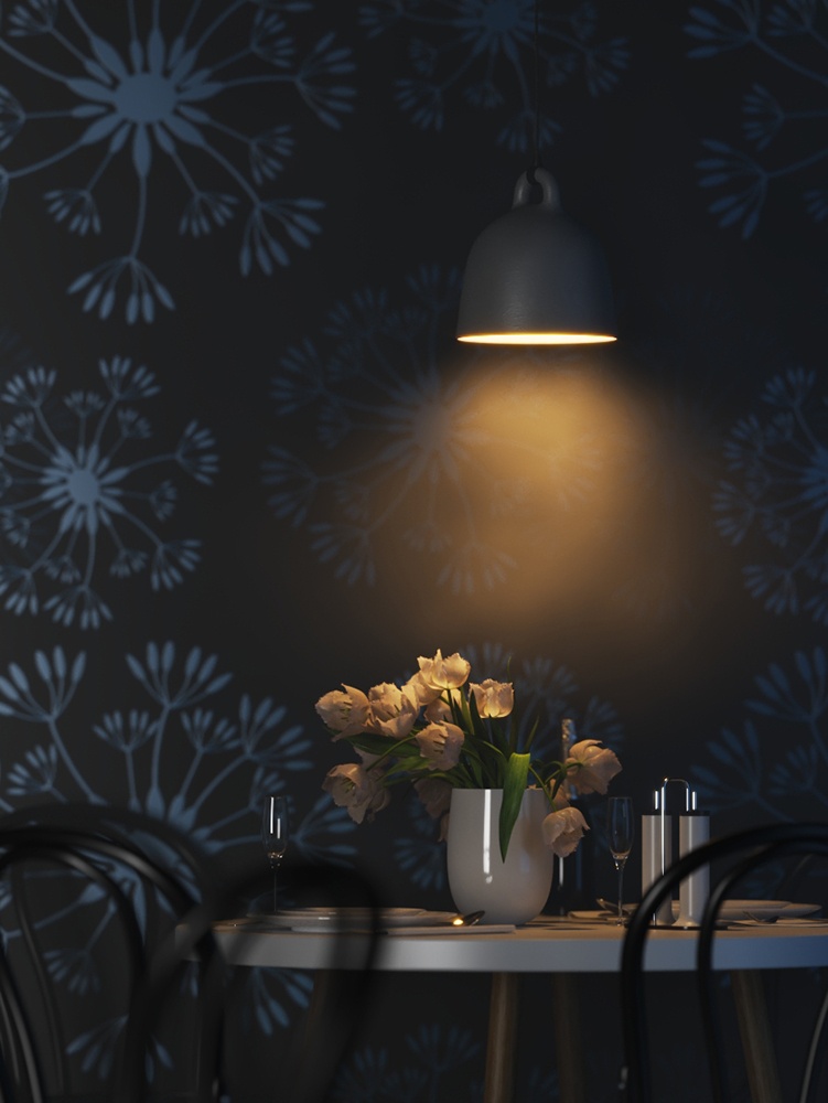
Decay Rollout
...
The Decay parameters determine how the light fades in and out. The Near Decay determines how light fades in. The light isn't at its maximum value at its source, but instead gradually increases until it reaches the Near end. The Far Decay determines how light fades out. The light isn't at its maximum value at its end, but instead gradually decreases after the Far start.
...
| Section | |||||||||||||||||||||||||||||||
|---|---|---|---|---|---|---|---|---|---|---|---|---|---|---|---|---|---|---|---|---|---|---|---|---|---|---|---|---|---|---|---|
|
...
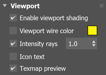
Viewport Rollout
...
| Section | |||||||||||||||
|---|---|---|---|---|---|---|---|---|---|---|---|---|---|---|---|
|
...