![]()
Page History
This page provides information about the LiquidSrc component in Phoenix for 3ds Max.
Overview
...
| Section | |||||
|---|---|---|---|---|---|
|
...
The Liquid Source interacts by default with all simulators in the scene. If you have many simulators in the scene, you can restrict the source from emitting into certain simulators using the Include/Exclude lists of the Simulators.
Each individual fluid channel includes a Mask slot for modulation with a texture across the surface or the volume of the geometry, and also a checkbox for controlling whether or not the Source will affect the corresponding channel. Also, note that if Emit Mode is set to Volume Brush or Volume Inject, the Map cannot use Explicit Map Channel or Vertex Color Channel mapping, because these apply only for the surface of the geometry.
Additionally, each parameter can have one or many Discharge Modifiers, allowing the emission to change depending on the surface properties for each different voxel of the emitter.
...
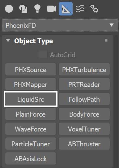
| title | UI Path: ||Create panel|| > Helpers > PhoenixFD category > LiquidSrc button |
|---|
|
| UI Expand | ||
|---|---|---|
| ||
|
Parameters
...
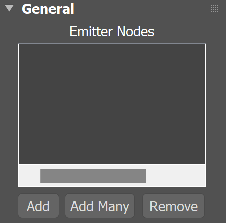
Emitter Nodes
...
| UI Text Box | ||
|---|---|---|
| ||
Non-Phoenix particles, such as Particle Flow ortyFlow particles, can also act as emitters for a Phoenix Source. They can emit from a spherical 3D shape, or from instanced geometry. |
| UI Text Box | ||
|---|---|---|
| ||
Note that the Source icon itself does not emit fluid, so the position of the icon's viewport gizmo in the scene does not matter. Instead, you must pick the geometry and/or particles that you want to use as emitters, in the Source’s Emitter Nodes list. |
| Section | ||||||||||||||||||||||
|---|---|---|---|---|---|---|---|---|---|---|---|---|---|---|---|---|---|---|---|---|---|---|
|
General
...
| UI Text Box | ||
|---|---|---|
| ||
Fluid can be emitted from a geometry’s surface, or from the entire volume of an emitting geometry. Note that if the Emit Mode is set to Volume Brush or Volume Inject, and you have a Texture Mask using either Explicit Map Channel or Vertex Color Channel mapping, then the Mask will be applied on the whole volume, based on the closest geometry surface. |
| UI Text Box | ||
|---|---|---|
| ||
Even if you do not simulate visible fluid like liquid, there can still be Velocity simulated within the grid, if for example, you animate an object to move around inside the grid to stir the Velocity channel. The simulated velocity can also be previewed in the viewport, or even rendered. |
| Section | ||||||||||||||||||||||||||
|---|---|---|---|---|---|---|---|---|---|---|---|---|---|---|---|---|---|---|---|---|---|---|---|---|---|---|
|
Liquid & RGB
...
| Section | ||||||||||||||||||||
|---|---|---|---|---|---|---|---|---|---|---|---|---|---|---|---|---|---|---|---|---|
|
Viscosity
...
| Section | |||||||||||||||
|---|---|---|---|---|---|---|---|---|---|---|---|---|---|---|---|
|
Particles
...
| Section | |||||||||||||||
|---|---|---|---|---|---|---|---|---|---|---|---|---|---|---|---|
|
Emission
...
| Section | |||||
|---|---|---|---|---|---|
|
Parameters
Emitter Nodes
...
| Div | ||||
|---|---|---|---|---|
| ||||
Emitter Nodes | sources – Specifies a list of objects that will emit fluid. Press the Add button and use the Left Mouse Button to select an object in the Viewport or a list of objects using the Scene Explorer. Can pick Phoenix | pick_ph – When enabled, allows Phoenix FD Simulators to be selected as an emitter in the list above. This usually involves more complicated setups. For additional information, please head over to the Interactions Between Simulators page. |
General
...
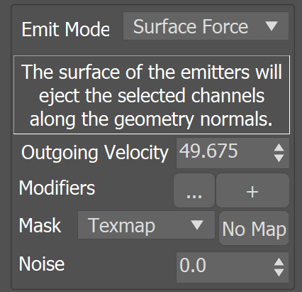
Emit Mode | ifnotsolid – Specifies the way the objects in the Emitter Nodes emit fluid.
Volume Inject – The volume of the emitters will discharge the selected fluid channels with added pressure. When this mode is selected, the discharge parameter is named Inject Power and it specifies the added volume of the injected fluid per second. This mode is useful for getting explosive discharge. In order to emit from the volumes of objects, this mode requires that all selected emitters are set into non-Solid mode from their Per-Node Properties.
Volume Brush – The fluid inside the volume of the emitters will gradually change towards the selected channel values. When this mode is selected, the discharge parameter is named Brush Effect (%) and it specifies the rate at which the transition takes place. When Brush Effect (%) is 100%, the fluid will immediately reach the selected values, and if Brush Effect (%) is less, it specifies how close the fluid values will get to the values from the source in 1 second. E.g. if the fluid inside an emitter's volume Temperature is 1000 and the Source emits Temperature 2000 with Brush Effect (%) of 80%, then after 1 second the temperature will have risen to 1800. This mode is useful for creating standing volumes of fluid with a high Brush Effect (%), or alternatively - to slowly convert the fluid inside the volume of the emitters to the values selected below over a period of time. In order to affect the volumes of objects, this mode requires that all selected emitters are set into non-Solid mode from their Per-Node Properties.
Surface Force – The surface of the emitters will eject the selected fluid channels along the geometry normals. The fluid's velocity follows the normals of the emitter geometry, so it is important to make sure they are not pointing inwards. When this mode is selected, the discharge parameter is named Outgoing Velocity and it specifies the speed of the emitted fluid in units/sec. The displayed units will change accordingly if the scene units change. This mode can work with emitter objects which are either Solid, or non-Solid in their Per-Node Properties.
| UI Text Box | ||||
|---|---|---|---|---|
| ||||
When using particles as source geometry, the Surface Force Emit Mode is not supported - Phoenix FD will automatically fall back to Volume Inject mode. |
Inject Power / Brush Effect (%) / Outgoing Velocity | discharge / brusheffect / outvel – These parameters control the strength of the source. Check Emit Mode for more info.
Mask | dmap, usedmap – Allows you to vary the Outgoing Velocity, Inject Power or Brush Effect (%) over the surface or the volume of the emitters. White areas of this map will have the strongest discharge, while black areas of the map will not discharge at all. The individual fluid channels can also be modulated using dedicated maps from the options below.
Modifiers | dmoddisch – Discharge Modifiers can be attached here in order to affect the Outgoing Velocity, Inject Power or Brush Effect (%) parameters.
Noise | noise – Varies the Outgoing Velocity, Inject Power and Brush Effect (%) across the surface or the volume of the emitting geometry or particle. The variation also changes over time.
Liquid & RGB
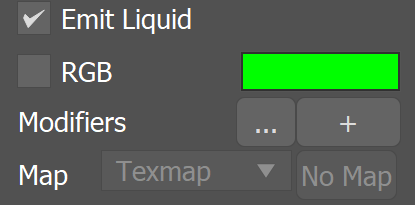
Emit Liquid – Enables or disables liquid emission. Disabling this option is useful in situations where only foam and splashes need to be emitted but not the liquid itself.
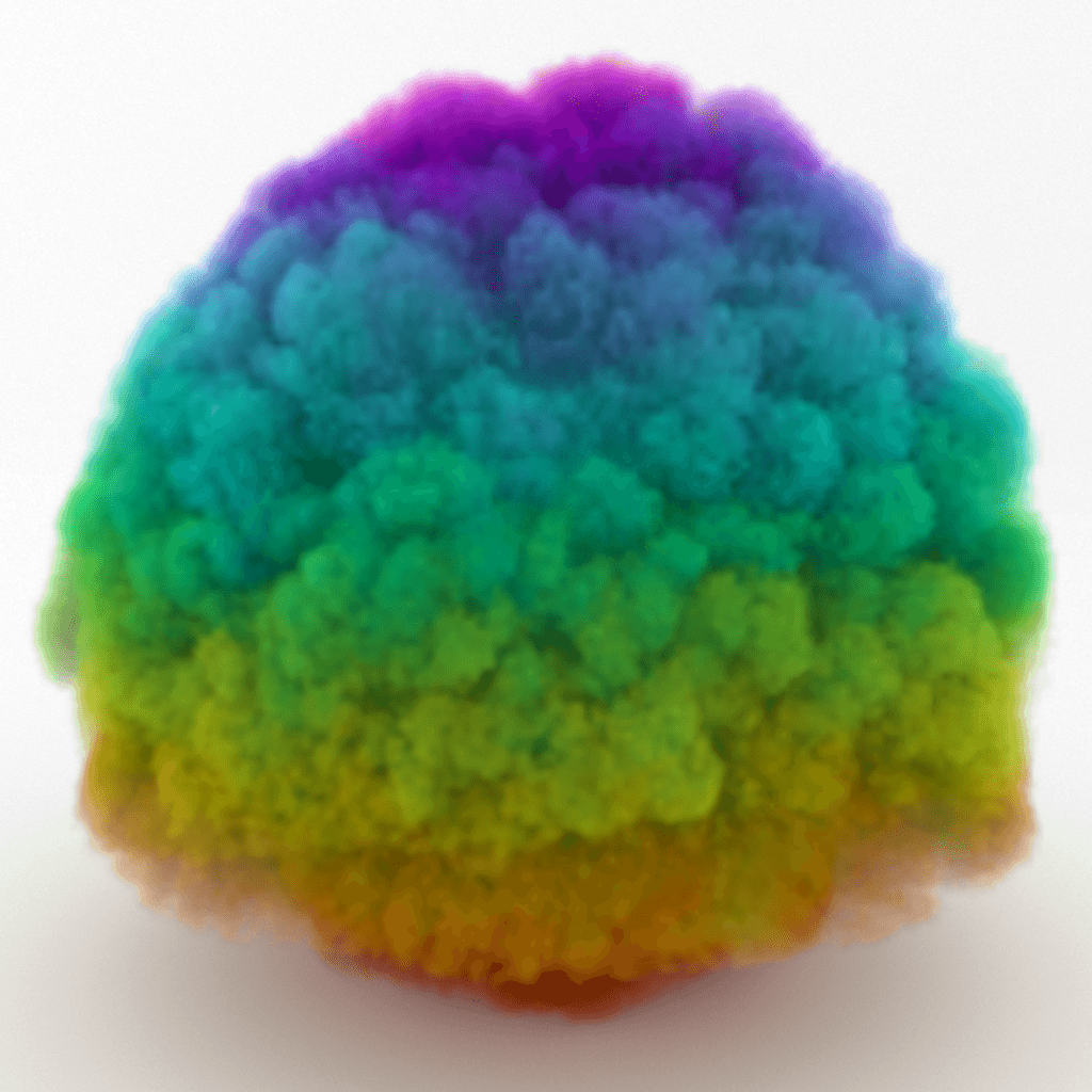
RGB | uvw, useuvw – If the RGB Map is not enabled, the emitted fluid's RGB channel will contain the specified color. If the RGB Map is enabled, the RGB values from the texture map will be used instead of the color swatch. If the RGB channel is not enabled in the Output rollout of the Simulator, this parameter will be ignored. Also, note that if Emit Mode is set to Volume Brush or Volume Inject, the Map cannot use Explicit Map Channel or Vertex Color Channel mapping, because these apply only for the surface of the geometry.
Modifiers | dmodrgb – A discharge modifier can be attached here in order to affect the RGB parameter.
...
|
...
|
...
|
...
|
...
|
...
|
...
|
Texture UVW
...
| Section | ||||||||||||||||||||
|---|---|---|---|---|---|---|---|---|---|---|---|---|---|---|---|---|---|---|---|---|
|
| Anchor | ||||
|---|---|---|---|---|
|
Example: Inherit TexUVW with Variation
...
| UI Text Box | ||
|---|---|---|
| ||
The following video provides examples of Inherited Texture UVW coordinates repeating along the V-axis over 0, 1 and 2 seconds. When Variation is set to 0, the V coordinate remains static. If Variation is set to 1, it takes one second for a full repetition/tile along the V-axis. |
| Align | ||
|---|---|---|
| ||
|
Emission from Particles
...
| Section | |||||
|---|---|---|---|---|---|
|
| UI Text Box | ||||
|---|---|---|---|---|
| ||||
To render these RGB colors for smoke, set the Smoke Color Based On parameter to RGB. For rendering of meshed liquids, set a Grid Texture as the Diffuse map for a Standard or V-Ray Material, and set the Grid texture's Channel to RGB. For more information, see the RGB Map Vertex Color example below. |
Particles
...
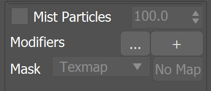
Particles | particles, useprt – Allows the source to emit particles into the Simulator. The particle birth rate is in thousands of particles per second.
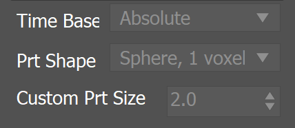
Type | prttype – Specifies the type of particles created by this source:
Drag – This option is not supported by the Liquid Source. In a Fire/Smoke Simulation, these particles are simply carried by the velocity of the simulation, without interacting with one another. In a Liquid Simulation, a similar behavior is provided by the liquid particles which can be rendered using a Phoenix FD Particle Shader. If necessary, the Count Multiplier setting on the Particle Shader can be used to increase or decrease the density of the particles.
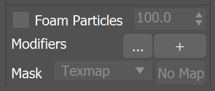
Foam – The source will emit Foam particles. Note that Foam simulation must be enabled from the Simulator so this type of particles can be emitted into it.
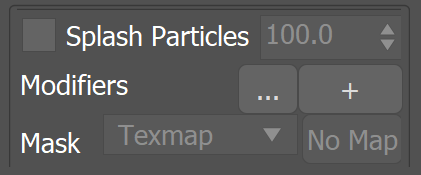
Splashes – The source will emit Splash particles. Note that Splash simulation must be enabled from the Simulator so this type of particles can be emitted into it.
Modifiers | dmodprt – A discharge modifier can be attached here in order to affect the Particles parameter.
Mask | prtmap, useprtmap – Allows you to vary the amount of particles over the surface or the volume of the emitters. If this is not used, the Source will emit equal amount of particles over the entire surface or volume of the emitters.
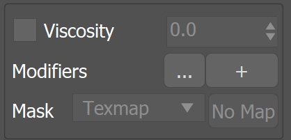
Viscosity
Viscosity | viscosity, usevisc – Specifies the viscosity of emitted liquid. If the viscosity channel is not enabled in the Output rollout of the Simulator, this parameter will be ignored.
Modifiers | dmodvisc – Discharge Modifiers can be attached here in order to affect the Viscosity parameter. The modifier ramp works as a multiplier to the Viscosity value.
Map | viscmap, useviscmap – Allows you to vary the viscosity over the surface or the volume of the emitters. If this is not used, the Source will emit equal viscosity over the entire surface or volume of the emitters.
None – The Viscosity channel will not vary.
TexMap – Allows you to specify a texture map for the Viscosity channel.
Vertex Color – The Viscosity channel of the released fluid is determined by the emitter node's vertex colors.
Emission
...
...
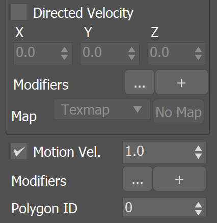
Motion Vel. | usevel, velmult – When enabled, moving emitters will affect the velocity of the fluid and make it follow the emitter. This effect is controlled with the specified multiplier. If the emitter is not moving, this option has no effect.
| UI Text Box | ||||
|---|---|---|---|---|
| ||||
|
Polygon ID | poly_id – Only the polygons with the specified ID of the emitter geometry will emit the fluid. This option affects the discharge only in Surface Force mode.
Texture UVW
| UI Text Box | ||||
|---|---|---|---|---|
| ||||
The main purpose of the Texture UVW feature is to provide dynamic UVW coordinates for texture mapping that follow the simulation. If such simulated texture coordinates are not present for mapping, textures assigned to your simulation will appear static, with the simulated content moving through the image. This undesired behavior is often referred to as 'texture swimming'. UVW coordinates are generated by simulating an additional Texture UVW Grid Channel which has to be enabled under the Output roll-out for the settings below to have any effect. For additional information on the Texture UVW feature, please check the Dynamics roll-out documentation. |
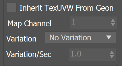
Inherit TexUVW From Geom | texuvw_geom – Sets the UVW Grid Channel value for each cell where fluid is emitted to the UV value of the emission geometry in that cell. As a consequence, modulating the Smoke Color with a texture on the very first frame will produce a render that looks very close to the original geometry, if the same texture was applied to it. When this option is disabled, the TexUVW values will be based on the position of the emission object inside the Simulator. Please check the Texture UVW example below.
Map Channel | texuvw_geom_ch – Specifies the Map Channel index to sample. This is useful when your geometry has multiple UV sets (called Map Channels in 3ds Max) with different layouts.
Variation | texuvw_var_mode – Variation is used to offset the UVW coordinates upon emission to avoid visible tiling once a texture is applied to the resulting simulation. Similarly to a printer, if the UVW channel is not varied, it would be like printing out the same sentence over and over again on each new line. When varied, the printer will change the line being printed. The following methods are available:
- No Variation
- Along U
- Along V
- Along W
- Along Grid Normals
- Along Object Normals
- Along World Normals
Variation/Sec | texuvw_var_speed – Controls the variation speed - the default value of 1 will cause textures assigned for rendering to repeat exactly once for every 30 frames (1 second) of the simulation.
Emission from Particles
...
|
...
|
...
|
...
| |||||||||
| medium |
|
...
|
...
Example: RGB Map Vertex Color
...
| Section | ||||||||||||||||||||||
|---|---|---|---|---|---|---|---|---|---|---|---|---|---|---|---|---|---|---|---|---|---|---|
|
...