![]()
Page History
...
| Div | ||||
|---|---|---|---|---|
| ||||
Time Scale | timescale – Specifies a time multiplier that can be used for slow motion effects. In order to achieve the same simulation look when changing the time scale, the Steps per frame value must be changed accordingly. For example, when decreasing the Time Scale from 1.0 to 0.5, Steps per frame must be decreased from 4 to 2. And of course, all animated objects in the scene (moving objects and sources) must be adjusted as well. Time Scale different than 1 will affect the Buildup Time of Particle/Voxel Tuners and the Phoenix Mapper. In order to get predictable results you will have to adjust the buildup time using this formula: |
| Div | |||||||
|---|---|---|---|---|---|---|---|
| |||||||
Cooling | cooling – This parameter controls the cooling of the fluid due to radiation. It gradually decreases the temperature until it reaches 300.
|
...
| Anchor | ||||
|---|---|---|---|---|
|
| Section | ||||||||||||||||||||||||||||||||||
|---|---|---|---|---|---|---|---|---|---|---|---|---|---|---|---|---|---|---|---|---|---|---|---|---|---|---|---|---|---|---|---|---|---|---|
Example: Steps Per Frame (SPF)
|
Active Bodies
| UI Text Box | ||||
|---|---|---|---|---|
| ||||
Interaction between Active Bodies and the Phoenix FD Fire/Smoke Simulator is not supported yet. |

Active Bodies | use_activeBodySolverNode – Enables the simulation of Active Bodies.
Solver | activeBodySolverNode – Specifies the Active Bodies Body Solver node holding the objects to be affected by the Phoenix FD Simulation.
| Anchor | ||||
|---|---|---|---|---|
|
Texture UVW
| UI Text Box | ||||
|---|---|---|---|---|
| ||||
The main purpose of the Texture UVW feature is to provide dynamic UVW coordinates for texture mapping that follow the simulation. If such simulated texture coordinates are not present for mapping, textures assigned to your simulation will appear static, with the simulated content moving through the image. This undesired behavior is often referred to as 'texture swimming'. UVW coordinates are generated by simulating an additional Texture UVW Grid Channel which has to be enabled under the Output roll-out for the settings below to have any effect. The custom UVW texture coordinates can be used for advanced render-time effects, such as recoloring of mixing fluids, modifying the opacity or fire intensity with a naturally moving texture, or natural movement of displacement over fire/smoke and liquid surfaces. Some examples uses are:
The Texture UVW channel values represent the UVW coordinates of each Cell in the Simulator, with a range of [ 0 - 1 ]. The channel is initialized when a simulation is started in one of two ways:
|
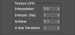
Interpolation | texuvw_interpol_influence – Blends between the UVW coordinates of the liquid particle at time of birth and its UVW coordinates at the current position in the Simulator. When set to 0, no interpolation will be performed - as a consequence, textures assigned to the fluid mesh will be stretched as the simulation progresses. This is best used for simulations of melting objects. When set to 1, the UVW coordinates of the fluid mesh will be updated with a frequency based on the Interpol.Step parameter - this will essentially re-project the UVWs to avoid stretching but cause the textures assigned to the fluid to 'pop' as the re-projection is applied. If you intend to apply e.g. a displacement map to a flowing river, set this parameter to a value between 0.1 and 0.3 - this will suppress both the effects of stretching and popping. See the Interpolation example below.
Interpol. Step | texuvw_interpol_step – Specifies the update frequency for the UVW coordinates. When set to 1, the UVWs are updated on every frame, taking into account the Interpolation parameter. See the Interpolation Step example below.
Antitear | texuvw_antitear_influence – Use this option when the assigned texture appears twisted, torn apart or otherwise distorted. This may happen when the simulation is moving very fast, therefore increase both the Antitear and A-tear Iterations to let Phoenix FD attempt to resolve the distortion.
A-tear Iterations | texuvw_antitear_iterations – The number of Antitear iterations performed for every Step of the simulation. Increasing this parameter will help resolve UVW distortion issues by allowing Phoenix FD to run the Antitear operation multiple times. Note that this may slightly increase the time it takes for the simulation to complete.
| Anchor | ||||
|---|---|---|---|---|
|
| Section | |||||||||||||||||||
|---|---|---|---|---|---|---|---|---|---|---|---|---|---|---|---|---|---|---|---|
Example: Interpolation
|
| Anchor | ||||
|---|---|---|---|---|
|
| Section | |||||||||||||||||||
|---|---|---|---|---|---|---|---|---|---|---|---|---|---|---|---|---|---|---|---|
Example: Interpolation Step
|