![]()
Page History
...
| UI Text Box | ||
|---|---|---|
| ||
UI Path: ||Select PhoenixFDSource|| > Attribute Editor > Discharge Modifiers rollout |
Parameters
...
| UI Text Box | ||
|---|---|---|
| ||
A list of modifiers modulate the emission using properties of the emission geometry at the point of interaction with the simulator. A ramp control is used to remap from the value of the specified property (i.e. Speed) to a multiplier ranging from 0.0 to 1.0. |
...
Diagram | modifiers[0].rampAlpha – The ramp diagram for mapping the source value of the emitter to a multiplier.
Example: Diagram Usage
...
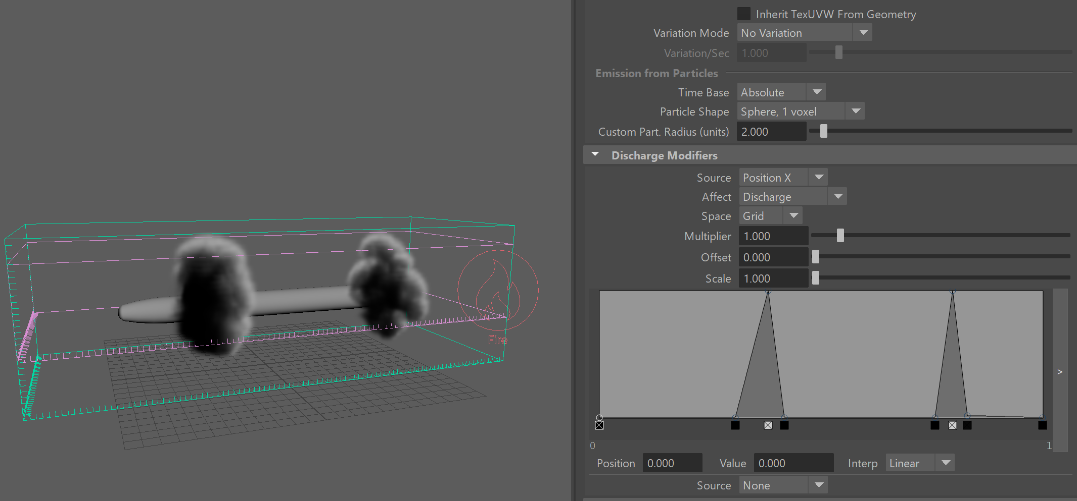
In the following setup, the Smoke value is modified by the position of each voxel along the X-axis in Gird coordinates. Note that in Grid Space, the coordinates will be normalized between 0 and 1, so no matter what the size of the simulator is, the diagram will rescale its function over the length of the simulator box. Along the vertical Y axis of the diagram is the effect of the discharge modifier, in this case - the amount of smoke.
Note that if you are simulating using Adaptive Grid and you want a discharge modifier by position to apply its effect always in the same position regardless of how the grid resizes, then you should change the Space to World and adjust the horizontal scale and position of the diagram so that it maps to the actual world coordinates.
| Section | |||||||||||||||||
|---|---|---|---|---|---|---|---|---|---|---|---|---|---|---|---|---|---|
|
...
...
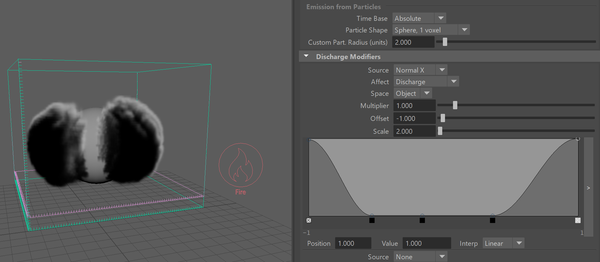
Another example is the following setup where the normals of the geometry are used to emit smoke. In this case, the normals are used in Object Space, so even if the object starts rotating, it would emit from the same areas. Note that the valid values for normals range from -1 to 1, instead of just 0 to 1. This way the negative values denote normals which point along the negative axis (in this case, to the left of the sphere), while the positive point along the axis direction from the object's transform (in this case, to the right of the sphere). In this example, the normal along the positive axis allows Smoke emission only when the normal's length along the object Y axis is between about 0.6 and 0.7, which means only from such normals which are at an angle and are neither horizontal nor vertical:
| Section | |||||||||||||||||
|---|---|---|---|---|---|---|---|---|---|---|---|---|---|---|---|---|---|
|
...
...
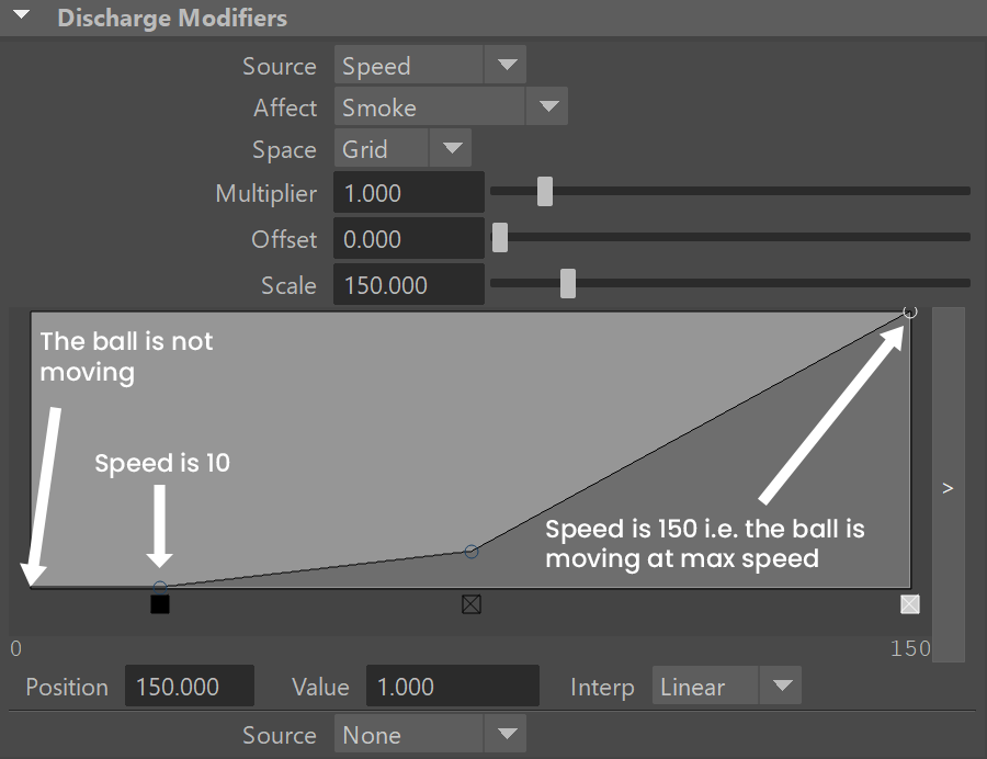
The following setup shows an accelerating ball which begins to emit smoke when it starts moving and emits denser smoke the faster it moves. The discharge modifier is set to the Smoke channel and the emission is set to Surface Force. This way the Surface Force will emit velocity out of the sphere during the entire sequence, but the smoke will get denser the faster the geometry moves and in the end when the geometry stops again, the emitted smoke density will go back to 0. You can check the range of the velocity value in the Simulation rollout's Cache File Content box - in this case the discharge modifier reaches the densest smoke emission when the speed goes above 150 and the emission starts when the speed goes above 10, so that a static object would not emit. These value are laid out on the horizontal axis, while the smoke density is mapped to the vertical axis of the Modifier Curve. Also note that the example uses Speed in Grid Space, but if you have a simulator connected to the geometry and moving, then it would be better to use World Space.
| Sectionalign | |||
|---|---|---|---|
| videoautoplayloop
| ||
| 0 | discharge_smoke_by_speed.mp4 | ||
| 1 | 800 | ||
| 2 | 450 | ||
| 3 | true | ||
| 4 | false | 5 | true|
|