Versions Compared

Key

  • This line was added.
  • This line was removed.
  • Formatting was changed.

...

Section
Column
width40%

Requires Phoenix FD 3.12.00 for V-Ray Next and V-Ray Next for Maya Hotfix 1 Official Release for Maya 2015 or newer. You can download official Phoenix and V-Ray from https://download.chaos.com. If you notice a major difference between the results shown here and the behavior of your setup, please reach us using the Support Form.

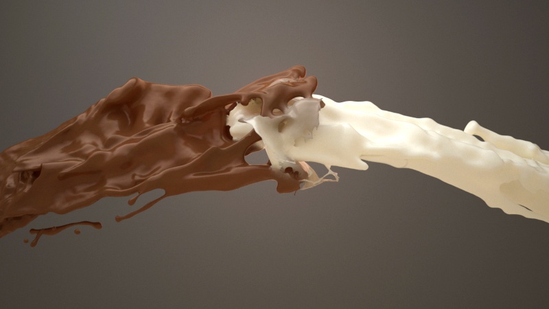
In this tutorial, we guide you through the creation of a fusion effect resulting from the splash of two fluids - milk and chocolate. For this goal, we create two liquid emitters, one for each liquid type. By using a Blend Material, we set the appearance of the mixture.

The two liquids are simulated with different RGB each, and then the grid RGB channel is extracted via a Phoenix Grid Texture and used as a mask for the Blend Material. We use Surface Tension to keep the liquid particles packed together in a smooth mesh and only allow them to break up into larger droplets.

To make the liquid mesh look even smoother, as a real milky-looking liquid, we use the Phoenix smoothing tools found in the Rendering rollout of the Simulator.

The Download button below provides you with an archive containing the start and end scenes as a reference.

UI Button
sizelarge
icondownload
titleDownload Project Files
urlhttps://drive.google.com/uc?export=download&id=1pZLhyndZpZt_J1dHZQWyT6DbHgguygLa

Column
width60%

Image Modified


System Units

...

Section
Column
width40%

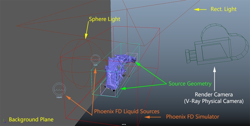
For a better understanding of how the scene components work together, take a look at the Scene Setup image. This is how the finished scene will be laid out.

The two liquid emitters are positioned facing each other, with the Chocolate emitter on the left and the Milk emitter on the right.

Two Phoenix Liquid Sources are created to generate liquid from the emitters.

Three lights are used in the scene:

A V-Ray Dome Light provides an overall diffuse illumination.

A V-Ray Rect. Light is placed above the Phoenix Simulator and acts as the key.

A V-Ray Sphere Light provides backlighting for translucency.

A background plane with a dark V-Ray Material is positioned behind the Phoenix Simulator to serve as a background. 

Column
width60%

Image Modified


Simulation Setup

...

Section
Column
width40%

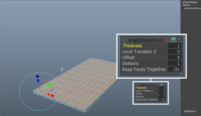
Create a regular Poly Plane and set the Width / Height to 23 / 42 respectively.

Extrude it with a Thickness of 1 to give it a volume.

UI Text Box
typewarning

Using open geometry or geometry with no thickness (such as the plane in this example) can give you unpredictable simulation results. Making sure that your geometry is clean is crucial for a smooth workflow. Phoenix (and many simulation packages in general) use a volumetric representation of the emission geometry for the simulation. The process of creating this volumetric representation is called voxelization. The algorithms responsible for voxelizing the geometry can fail when using open (with holes) or planar (no thickness) geometry.

The plane is extruded to turn into what is essentially a very thin box. This is enough to sort out any possible problems with the voxelization at simulation time.

Column
width60%

Image Modified


...


Section
Column
width40%

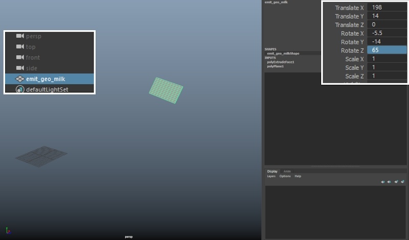
Rename the plane to emit_geo_milk.

UI Text Box
typeinfo

We will keep renaming the objects in the scene for the rest of the tutorial to avoid ambiguity when referring to a particular node.

If you'd like your setup to be identical to the provided scene files, here are the exact transformations of the emit_geo_milk:

Translate: [ 198, 14, 0 ]
Rotate: [ -5.5 , -14 , 65 ]

Column
width60%

Image Modified


...


Section
Column
width40%

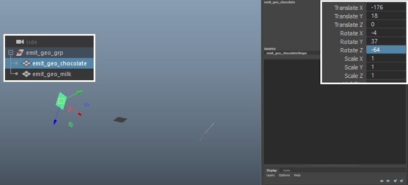
Duplicate emit_geo_milk and rename the copy to emit_geo_chocolate.

If you'd like your setup to be identical to the provided scene files, here are the exact transformations of the emit_geo_chocolate:

Translate: [ -176, 18, 0 ]
Rotate: [ -4 , 37 , -64 ]

Group both objects together by selecting them and pressing Control + G.

Rename the group to emit_geo_grp to keep the scene organized.

Column
width60%

Image Modified


...


Section
Column
width40%

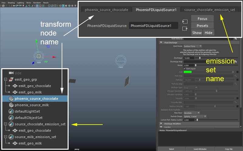
Add two Phoenix Liquid Sources and rename them to phoenix_source_chocolate and phoenix_source_milk respectively.

Optionally, you may want to rename the automatically generated sets as well - in this example, they have been renamed to source_chooclate_emission_set and source_milk_emission_set for clarity.

Add emit_geo_milk to the emission set of phoenix_source_milk by Middle-Mouse button dragging it in the Outliner.

Add emit_geo_chocolate to the emission set of phoenix_source_chocolate.

UI Text Box
typeinfo

The emission sets are used to tell the Liquid Source which objects in the scene are to be used as emitters. Those sets are automatically generated when you create a new Phoenix Fire Source or a Phoenix Liquid Source.

You can use the Middle-Mouse button in the Outliner to add new objects to any Maya set. If you'd like to remove an object already in a set, you can open the Relationship Editor by going to Windows → Relationship Editors → Sets.

Column
width60%

Image Modified


...


Section
Column
width40%

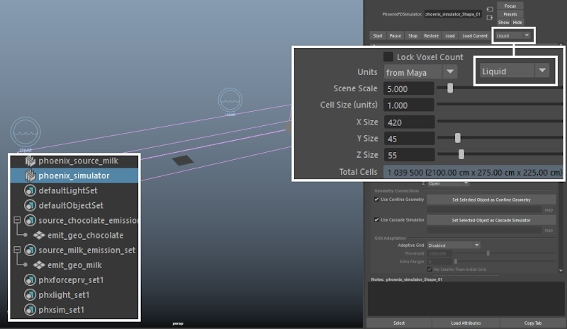
Create a Phoenix Liquid Simulator that envelops both source geometry objects - make sure to move it to the origin by zeroing-out the transform values in the Channel box.

UI Text Box
typewarning

Set the Simulation Type drop-down to Liquid. The Phoenix Simulator can work in two separate modes - Fire/Smoke and Liquid. This drop-down will hide most of the parameters related to fire/smoke simulations and automatically enable Liquid simulation for you.

If you'd like to do this manually instead, open the Liquid rollout and select Enable. Keep in mind that some Preview and Rendering settings may be less than ideal by default if you choose to go with the manual approach.

Open the Grid rollout and set the Cell Size to 1. The Cell Size parameter is your main control for the resolution of the simulation. The lower this value is, the longer the simulation will take but the more refined the result will be.

The exact values for the X / Y / Z size of the Simulator are [ 420, 45, 55 ].

Hit Start to run the simulation.

Column
width60%

Image Modified


...


true
Section
Column
width40%
UI Text Box
typetip

The emission is too weak.

We address this first by increasing the Discharge of the Liquid Sources.

Column
width60%
videoautoplayloop
Align
0001_fresh_simulator.mp4
1100%
2100%
3true
4false
aligncenter
HTML
<iframe width="800" height="450" src="https://www.youtube.com/embed/mbfZbYw_vQk?version=3&loop=1&playlist=mbfZbYw_vQk" frameborder="0" allowfullscreen></iframe>
5


...


Section
Column
width40%

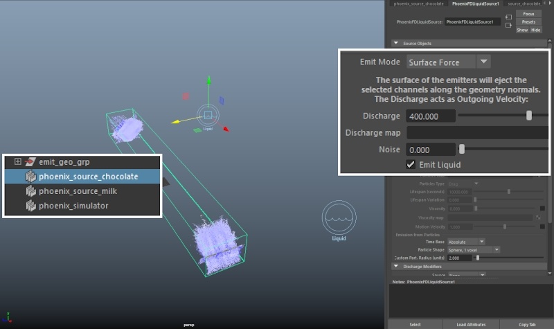
Increase the Discharge of both Liquid Sources to 400. The Discharge controls how strong the liquid is pushed in the direction of the geometry normals when the Emit Mode is set to Surface Force.

Column
width60%

Image Modified


...


Section
Column
width40%
UI Text Box
typetip

There are a few issues here:

  1. The Simulator box is too small.
  2. The Liquid Sources are emitting liquid in all directions.
  3. The emission is chaotic.

In the next step we enable Adaptive Grid to resolve the first issue.

Column
width60%
videoautoplayloop
Align
0002_higher_discharge.mp4
1100%
2100%
3true
4false
5true
aligncenter
HTML
<iframe width="800" height="450" src="https://www.youtube.com/embed/gwrsa2-4peY?version=3&loop=1&playlist=gwrsa2-4peY" frameborder="0" allowfullscreen></iframe>


...


Section
Column
width40%

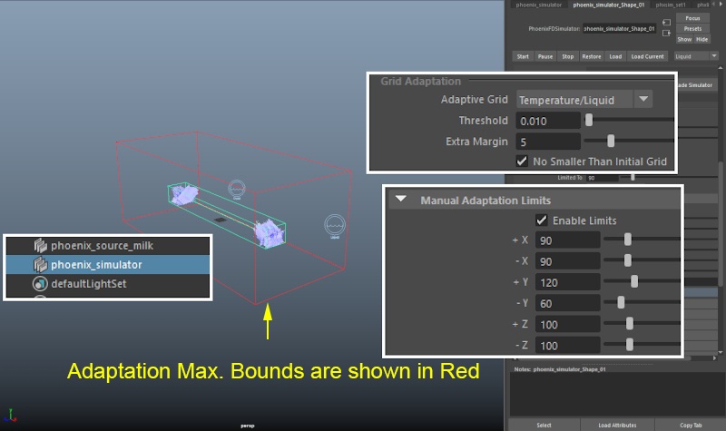
Select the Simulator and open the Grid rollout.

Enable Adaptive Grid by setting the Adaptive Grid parameter to Temperature/Liquid. This option specifies which simulation channel will be tracked by the Simulator to determine when the size of the grid is to be increased or decreased. Adaptive Grid is a huge time saver - the initial grid is dynamically expanded to accommodate the movement of the fluids, cutting down on both processing time and memory.

Reduce the Threshold value to 0.01. The grid will expand when the content of a cell near a border goes above this value.

If you notice any clipping, you may increase the Extra Margin to a value of 5 - 10. The Extra Margin acts as a 'buffer' area for the Threshold - instead of looking at the cells right at the border, the Adaptive Grid algorithm will look 5 cells deeper within the simulator and expand based on the contents there.

Select Enable Limits. The red box in the screenshot to the right is a preview of the Maximum Bounds for the simulation. Adaptive Grid is a huge time saver - the initial grid is dynamically expanded to accommodate the movement of the fluids, cutting down on both processing time and memory. This will add a few extra voxels at the borders during adaptation.

The exact values for the X / Y / Z limits are X: [ 90 / 90 ] Y: [ 120 / 60 ] Z: [ 100 / 100 ].

Column
width60%

Image Modified


...


Section
Column
width40%

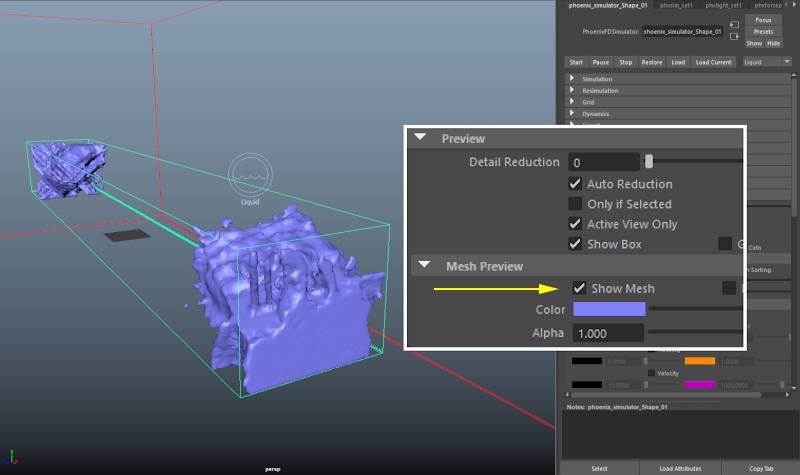
Open the Preview rollout and enable Mesh Preview.

Column
width60%

Image Modified


...


true
Section
Column
width40%
UI Text Box
typetip

The Liquid Sources are still emitting all over the place.

Ideally, we would like to emit only from the polygons facing the origin. We do this in the next step by limiting the emission using Discharge Modifiers.

Column
width60%
Align
align
videoautoplayloop
center
0003_adaptive_grid_mesh_preview.mp4
1100%
2100%
3true
4false
HTML
<iframe width="800" height="450" src="https://www.youtube.com/embed/zzV_i39Qo_U?version=3&loop=1&playlist=zzV_i39Qo_U" frameborder="0" allowfullscreen></iframe>
5


...


Section
Column
width40%

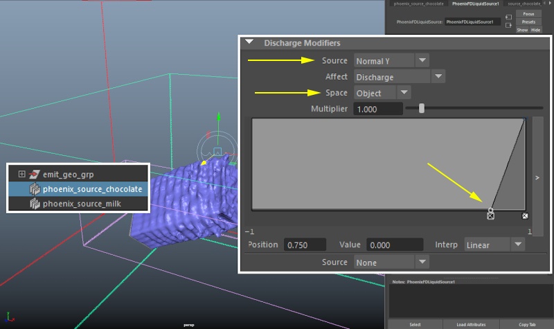
Select phoenix_source_chocolate and go to the Discharge Modifiers rollout.

Add a new Discharge Modifier by setting the Source option to Normal Y. The Source specifies what property of the emission geometry is used to to modify the value specified in the Affect drop-down. In this example, the Normal Y direction will be used to modify the Discharge.

Set the Space parameter to Object. When the Space parameter is set to Object, the normals of the geometry are computed before any transformations (such as moving or rotating) are applied. Because the source geometry was created flat on the XY axis and then moved and rotated into position, the faces pointing towards the origin actually have their object space normals pointing in positive Y.

Finally, move the left point of the graph such that it sits at position [ 0.75, 0.0 ].

Repeat the same steps for phoenix_source_milk.

Column
width60%

Image Modified


...


UI Text Box
typeinfo
Section
Column
width40%

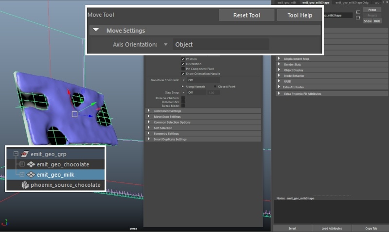
An easy way to check the Object Space orientation of your geometry would be to select it, invoke the Move tool and set the space to Object. The arrows of the move tool's gizmo will show you the object space orientation of your geometry.

In this example you can see that the green arrow ( Y axis) is pointing toward the origin.

This setup on the picture above is saying the following: "If the normal of the face is pointing in +Y in Object space, emit with a discharge multiplier of 1. Otherwise, set the multiplier to 0."

You can check the Discharge Modifiers page for more information and examples.

Column
width60%

Image Modified


...


true
Section
Column
width40%
UI Text Box
typetip

Now that we've managed to limit the emission, we can clearly see the stepping artifacts.

Those are happening because the Steps per Per Frame are not enough.

Column
width60%
Align
videoautoplayloop
aligncenter
0004_discharge_mods_added.mp4
1100%
2100%
3true
4false
HTML
<iframe width="800" height="450" src="https://www.youtube.com/embed/wT2x5C7J8vc?version=3&loop=1&playlist=wT2x5C7J8vc" frameborder="0" allowfullscreen></iframe>
5


...


Section
Column
width40%

Open the Dynamics rollout and set the Steps per Frame to 4.

The Steps per Frame parameter controls how many calculations are made between 2 consecutive frames. This includes the emitters as well. If you see stepping in the emission, as in this example, increasing the SPF is most likely your best option.

Column
width60%

Image Modified


...


Section
Column
width40%
UI Text Box
typetip

Things are looking much better now.

There are still artifacts present in the emission - it should be perfectly smooth yet you can clearly see the liquid breaking apart.

This is caused by the presence of the emission geometry inside the simulator. Turning it Non-Solid should resolve the issue.

Column
width60%

Videoautoplayloop
0005_spf_four.mp4
1100%
2100%
3true
4false
5true

Align
aligncenter
HTML
<iframe width="800" height="450" src="https://www.youtube.com/embed/9NPh1lHDglE?version=3&loop=1&playlist=9NPh1lHDglE" frameborder="0" allowfullscreen></iframe>


...


Section
Column
width40%

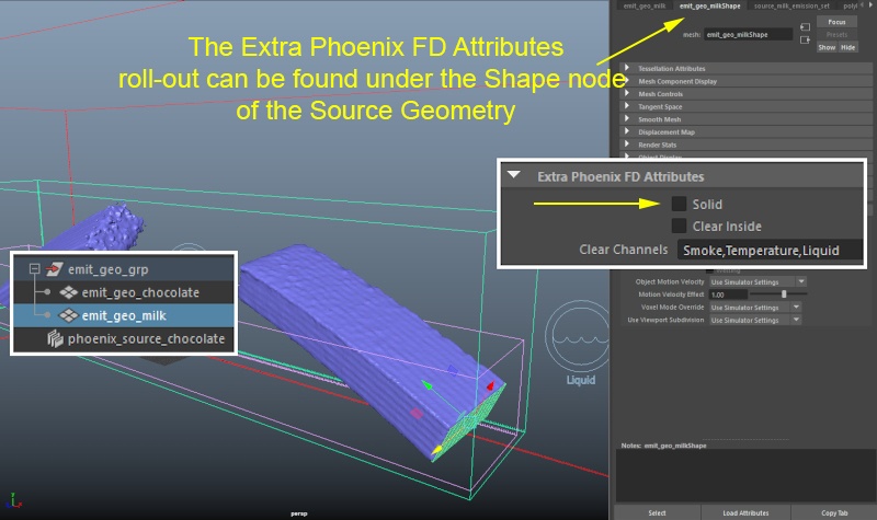
Disable the Solid option for emit_geo_milk and emit_geo_chocolate. This can be done for each object by first selecting it, opening the Attribute Editor, heading over to the Shape tab and expanding the Extra Phoenix FD Attributes rollout at the bottom.

Solid objects are treated as obstacles in the simulation. Even though the liquid is never on a direct collision course with the emission geometry, the presence of those solid objects in the simulation affects how the velocity is calculated. As a consequence, this is also affecting the motion of the liquid. The difference is minor but still noticeable.

Column
width60%

Image Modified


...


Section
Column
width40%
UI Text Box
typetip

With Solid disabled, the stream of liquid is finally looking smooth and steady.

Next we reduce the Scene Scale to dial back some of that force the liquid is colliding with.

Column
width60%
videoautoplayloop
Align
0005_02_solid_OFF_with_spf_four.mp4
1100%
2100%
3true
4false
5true
aligncenter
HTML
<iframe width="800" height="450" src="https://www.youtube.com/embed/FRK8JpCmhKU?version=3&loop=1&playlist=FRK8JpCmhKU" frameborder="0" allowfullscreen></iframe>


...


Section
Column
width40%

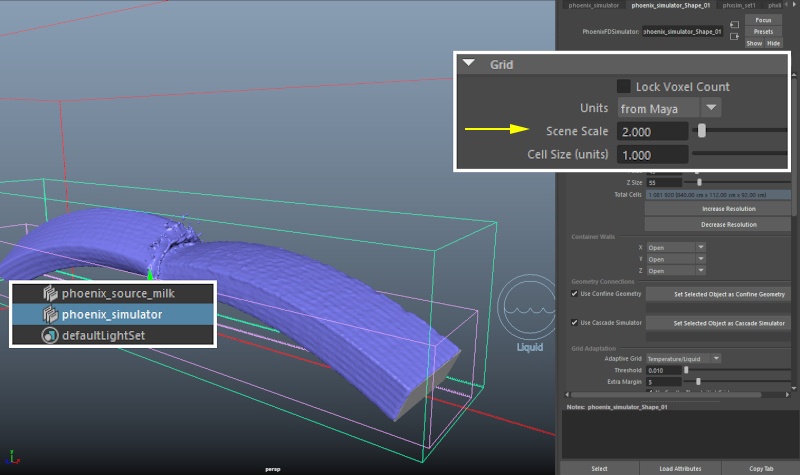
Under the Grid rollout, set the Scene Scale to 2. The Scene Scale parameter will affect most of the dynamics in the simulator. A smaller value will produce splashier, more turbulent movement while a larger Scene Scale will give the impression of a heavier, more inert fluid. You may experiment with this parameter but keep in mind that you will also have to adjust the Discharge of the Phoenix Sources as well.

Column
width60%

Image Modified


...


Section
Column
width40%
UI Text Box
typetip

Because the liquid is moving too fast, in the next step we reduce the Gravity and Time Scale from the Dynamics rollout of the Simulator.

Column
width60%
Align
align
videoautoplayloop
center
0006_lower_scene_scale.mp4
1100%
2100%
3true
4false
5true
HTML
<iframe width="800" height="450" src="https://www.youtube.com/embed/g6YqdYwyRNg?version=3&loop=1&playlist=g6YqdYwyRNg" frameborder="0" allowfullscreen></iframe>


...


Section
Column
width40%

In the Dynamics rollout , reduce Gravity and Time Scale to 0.5.

The Gravity parameter is self-explanatory - the liquid will fall down slower when this value is lower.

Time Scale is very similar to the Steps per Per Frame parameter in a sense that it also scales down the velocities in your simulation, thus removing detail from the sim. You should be mindful of this when tweaking your setup.

If you'd like to significantly slow down a liquid simulation, a better approach would be to use the Time Bend Controls section of the Input rollout. We don't make use of these as the RGB channel blending (for slow-down) is not supported at the time of writing this tutorial.

Column
width60%

Image Modified


...


Section
Column
width40%
UI Text Box
typetip

The general motion of the liquid is now taken care of.

We can break up the uniformity by modulating the Discharge of the Liquid Sources with a texture.

Column
width60%

Videoautoplayloop
0007_lower_gravity_timescale.mp4
1100%
2100%
3true
4false
5true

Align
aligncenter
HTML
<iframe width="800" height="450" src="https://www.youtube.com/embed/w3es_J5saTU?version=3&loop=1&playlist=w3es_J5saTU" frameborder="0" allowfullscreen></iframe>


...


Section
Column
width40%

Let's first assign a new Lambert material to emit_geo_chocolate so we can see the tweaks we're making to the texture in the Viewport.

Rename the material to mat_emit_preview_choco.

Plug a Volume Noise texture in the Diffuse slot.

UI Text Box
typewarning

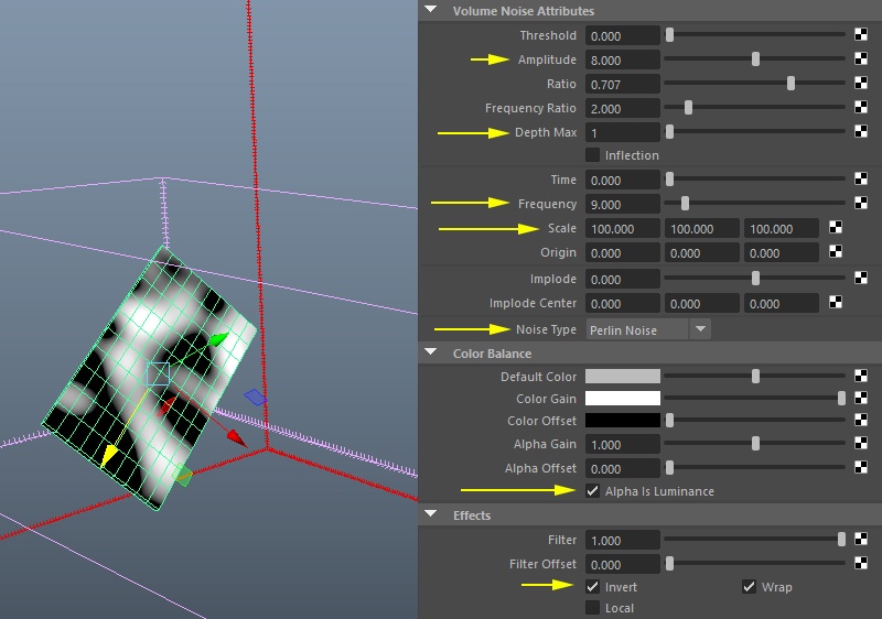
Enable Alpha is Luminance under the Color Balance rollout or the texture will have no effect. By default, Phoenix looks at the Alpha of the texture. The Alpha is Luminance toggle creates an alpha channel based on the RGB luminance.

Dial in the following values for the Volume Noise texture:

Noise Type: Perlin Noise,
Amplitude: 8,
Depth Max: 1,
Frequency: 9,
Scale: 100/100/100,
Enable Effects → Invert

UI Text Box
typetip

Those values are purely subjective. The sole purpose of this texture is to break-up the emission in an interesting pattern. You can experiment to find a setup you like.

Column
width60%

Image Modified


...


Section
Column
width40%

Repeat the same steps for emit_geo_milk.

Assign a new Lambert material to emit_geo_milk and rename it to mat_emit_preview_milk.

Plug a Volume Noise texture in the Diffuse slot of the material.

UI Text Box
typewarning

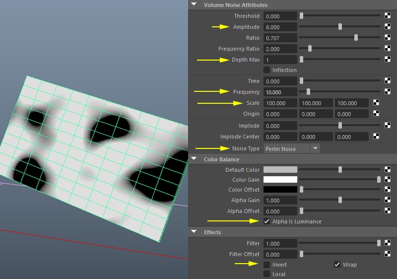
Enable Alpha is Luminance under the Color Balance rollout or the texture will have no effect. By default, Phoenix looks at the Alpha of the texture. The Alpha is Luminance toggle creates an alpha channel based on the RGB luminance.

Dial in the following values for the Volume Noise texture:

Noise Type: Perlin Noise,
Amplitude: 8,
Depth Max: 1,
Frequency: 10,
Scale: 100/100/100,
Disable Effects → Invert

Column
width60%

Image Modified


...


Section
Column
width40%

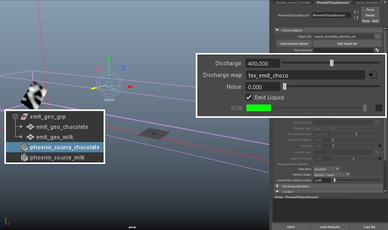
Plug each Volume Noise texture to the Discharge map slot of the corresponding Phoenix Liquid Source.

Column
width60%

Image Modified


...


Section
Column
width40%
UI Text Box
typetip

At the moment, the texture is static which produces an uninteresting result.

We can animate the placement node to further break up the emission.

Column
width60%

Videoautoplayloop
0008_discharge_map_texture.mp4
1100%
2100%
3true
4false
5true

Align
aligncenter
HTML
<iframe width="800" height="450" src="https://www.youtube.com/embed/P4DhCB26fM0?version=3&loop=1&playlist=P4DhCB26fM0" frameborder="0" allowfullscreen></iframe>


...


Section
Column
width40%

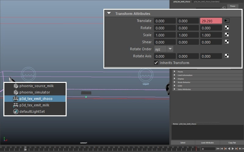
Animate the Translate: Z parameter of the 3d placement nodes for each Volume Noise texture such that it goes from 0 to 100 during frames 0 to 100.

The exact key frames are:

Frame: 0 – Translate Z: 0
Frame: 100 – Translate Z: 100

Column
width60%

Image Removed


Section
Column
width50%

Videoautoplayloop
0009_discharge_map_animated_placement.mp4
1100%
2100%
3true
4false
5true

Column
width50%

Videoautoplayloop
0009_discharge_map_animated_placement_simulation.mp4
1100%
2100%
3true
4false
5true

Z: 100

Column
width60%

Image Added


...


Section
Column
width40%

 Here's the emission when modulated by the animated Volume Noise texture.

Column
width60%
Align
aligncenter
HTML
<iframe width="800" height="450" src="https://www.youtube.com/embed/lGCjmEm3N6Q?version=3&loop=1&playlist=lGCjmEm3N6Q" frameborder="0" allowfullscreen></iframe>


...


Section
Column
width40%

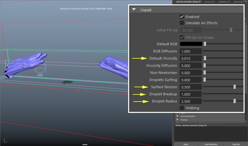
Because the fluid is behaving like pure water at the moment, we tweak the Viscosity and Surface Tension parameters to give it some thickness.

Set Liquid → Surface Tension to 0.5. The Surface Tension parametercontrols the force produced along the curvature of the liquid surface - this keeps the liquid from breaking into individual particles when a force is applied to it.

Set the Droplet Breakup to 1.0, with a Droplet Radius of 2.5 cells. The Droplet Breakup balances between the liquid forming tendrils or droplets. Larger values will produce more droplets.

Droplet Radius controls the radius of the droplets formed by the Droplet Breakup parameter (in voxels). Therefore, if you increase the resolution of the grid, you should also increase the Droplet Radius.

Set Viscosity to 0.01. Viscosity emulates thickness - the higher this value is, the more the liquid will resemble thick mud, honey or tar.

UI Text Box
typeinfo

Phoenix supports the simulation of liquids with varying viscosity. If you'd like to give different viscosity values to the milk and chocolate liquids, you simply need to select the Phoenix Liquid Sources, enable Viscosity and give the parameter a value. Also, don't forget to enable the Grid and Particle Viscosity channel output from the Output rollout . At this point, the Dynamics → Viscosity Diffusion parameter controls how the two thicknesses of the liquids emitted from the two sources will mix.

To keep this tutorial short and easy to follow, this workflow is omitted.


Column
width60%

Image Modified


...


Section
Column
width40%
UI Text Box
sizemedium
typetip

In the next step we add a Bend deformer to spread the emitted fluid in an arc rather than the cubic shape we've got at the moment.

Column
width60%

Videoautoplayloop
0010_inc_surfTension_Viscosity.mp4
1100%
2100%
3true
4false
5true

Align
aligncenter
HTML
<iframe width="800" height="450" src="https://www.youtube.com/embed/1zeO-rPKdcc?version=3&loop=1&playlist=1zeO-rPKdcc" frameborder="0" allowfullscreen></iframe>


...


Section
Column
width40%

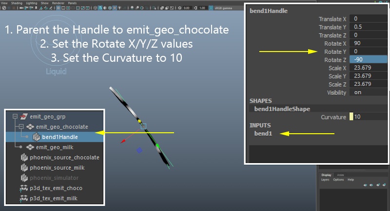
Add a new Deform → Non-Linear → Bend deformer to emit_geo_chocolate.

Set the Curvature to 10.

If you'd like your setup to be identical, do the following steps:

  1. Parent the bend handle to emit_geo_chocolate.
  2. Set the Rotate values to (90, 0, - 90).
Column
width60%

Image Modified


...


Section
Column
width40%

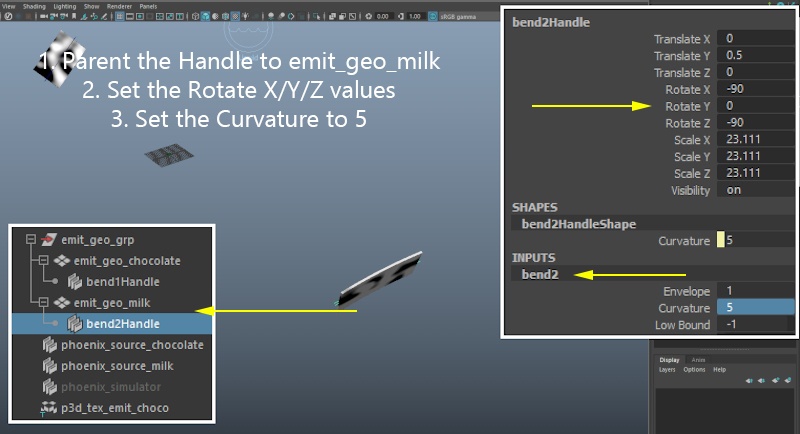
Repeat the same steps for emit_geo_milk.

Set the Curvature to 5.

If you'd like your setup to be identical, do the following steps:

  1. Parent the bend handle to emit_geo_milk.
  2. Set the Rotate values to (-90, 0, - 90).
Column
width60%

Image Modified


...


Section
Column
width40%
UI Text Box
typetip

Here's how the simulation looks now.

At this point we're done with the tweaks. The only thing left to do is to enable the emission of RGB which will be used as a mask for the Blend material, and to increase the resolution of the Simulator.

true
Column
width60%60%
Align
aligncenter
HTML
<iframe width="800" height="450" src="https://www.youtube.com/embed/pWRaQ7KbU4Q?version=3&loop=1&playlist=pWRaQ7KbU4Q" frameborder="0" allowfullscreen></iframe>
Videoautoplayloop
0011_add_bend_modifiers.mp4
1100%
2100%
3true
4false
5


...


Section
Column
width40%

Enable the emission of RGB on phoenix_source_chocolate and set the RGB Color to White (255, 255, 255).

Column
width60%

Image Modified


...


Section
Column
width40%

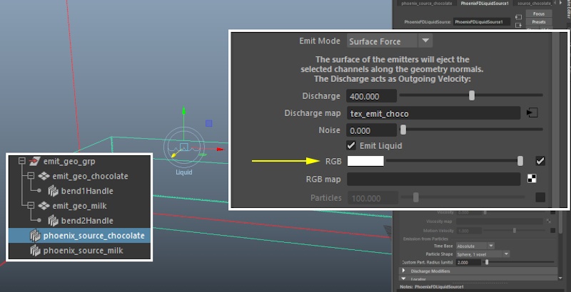
Enable the emission of RGB on phoenix_source_milk and set the RGB Color to Black (0, 0, 0).

Column
width60%

Image Modified

...


...


Section
Column
width40%

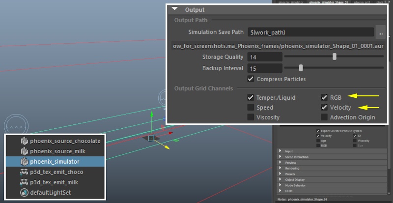
Select the Simulator and enable the export of the RGB and Velocity Grid channels from the Output rollout.

Doing this will tell Phoenix to store the information for those channels in the cache files on disk.

The Velocity channel is required when rendering the simulation with Motion Blur.

The RGB channel we need for a mask for the Blend Material used for the final render.

Column
width60%

Image Modified


...


Section
Column
width40%

Open the Grid rollout and reduce the Cell Size to 0.64.

Hit Start to cache the final simulation to disk.

UI Text Box
typetip

 Disabling the Preview → Mesh Preview will slightly speed up the simulation.

Column
width60%

Image Modified


...


Section
Column
width40%
UI Text Box
typetip

Here's the simulation result.

In the next step we start adding lights and materials to our scene for the final render.

Column
width60%

Videoautoplayloop
0012_final_res.mp4
1100%
2100%
3true
4false
5true

for the final render.

Column
width60%
Align
aligncenter
HTML
<iframe width="800" height="450" src="https://www.youtube.com/embed/d3Cmqjfv2BQ?version=3&loop=1&playlist=d3Cmqjfv2BQ" frameborder="0" allowfullscreen></iframe>


Rendering Setup

...

Section
Column
width40%

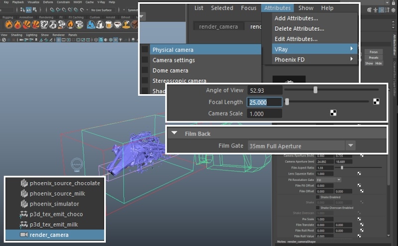
Add a Camera and set the following transform values in the Channel Box:

Translate: [ 1.4 , 115 , 306 ]
Rotate: [ -12 , 1, 0 ]

Set the Film Gate to 35mm Full Apperture, with a Focal Length of 25.

Add V-Ray Physical Camera attributes from the Attribute Editor → Attributes menu → Vray.

Set the F-number to 1.4, Shutter Speed to 300, ISO to 100 and select Enable Vignetting.

Column
width60%

Image Modified


...


Section
Column
width40%

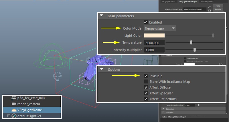
We first create our Fill Light.

Add a V-Ray Dome light to the scene.

Set the Color Mode to Temperature, and the Temperature parameter to 5000 to give the lighting a warm tint.

Set the Options → Invisible to Enabled so the dome light is not visible in the final image.

Column
width60%

Image Modified


...


Section
Column
width40%

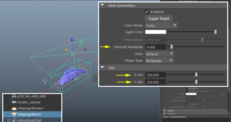
Let's add a Key Light.

Create a V-Ray Rect. Light and transform it to the following coordinates:

Translate: [ 0, 288, 20 ]
Rotate: [ -89 , -14 , 7 ]

Set the Intensity Multiplier to 6.

Increase the U/V Size to 350/230.

Column
width60%

Image Modified


...


Section
Column
width40%

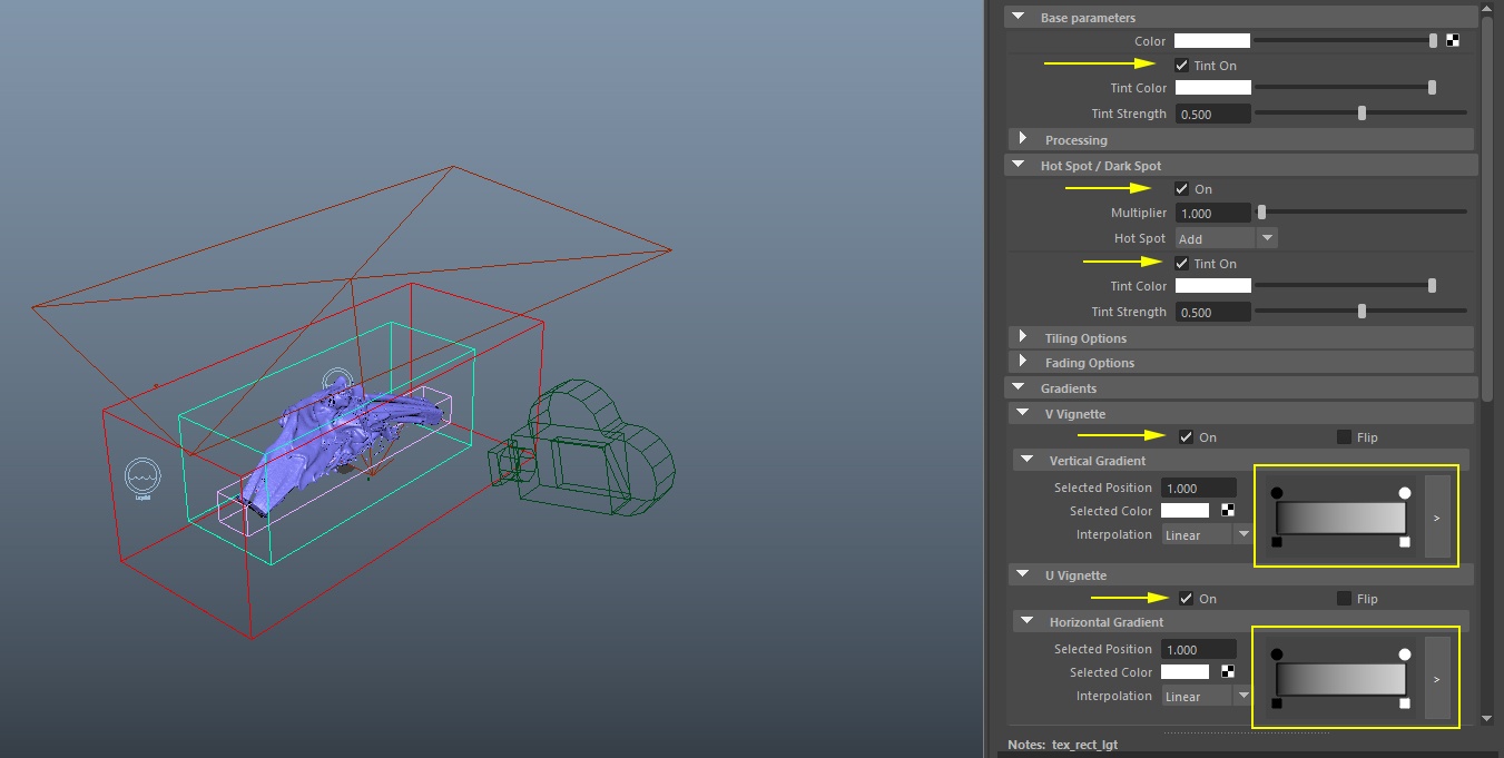
To give the Key Light a softer emission pattern, enable Use Rect. Tex and plug a VRay Softbox texture in the Rect. Tex slot.

Enable Base → Tint On.

Enable Hot Spot / Dark Spot → On.

Enable Hot Spot / Dark Spot → Tint On.

Enable U and V Vignette and set the Horizontal and Vertical Gradient Color Ramps to go from black to white.

Column
width60%

...

Section
Column
width40%
UI Text Box
typetip

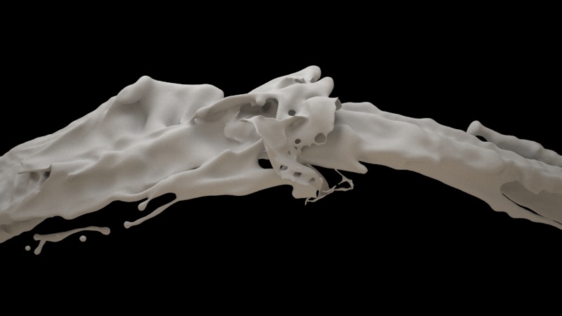
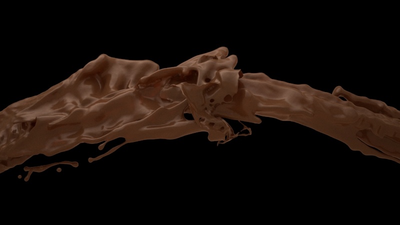
Here's a rendered image with a default Lambert material.

The surface of the liquid looks rough. Both milk and chocolate tend to be quite reflective and almost perfectly smooth.

Column
width60%

Image Modified

...


...


Section
Column
width40%

Select the Phoenix Simulator and go to Rendering → Mesh rollout.

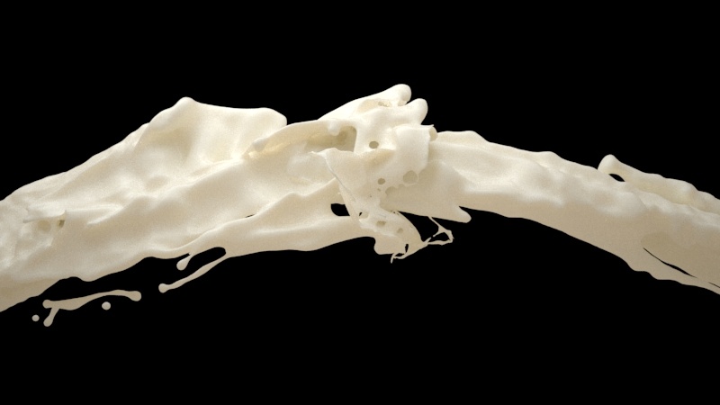
Set the Mesh Smoothness parameter to 2 and enable Use Liquid Particles for Smoothing.

Set the Smoothing Particle Size to 0.4.

To the right is a rendered image with those settings. The surface is now much smoother.

Column
width60%

Image Modified


...


Section
Column
width40%

Let's create the Chocolate material.

Assign a V-Ray Material to the Phoenix Simulator and rename it to mat_chocolate.

Set the following settings:

Diffuse Color: 0.094, 0.031, 0.012
BRDF Type: Phong
Reflection Color: 0.431 , 0.290, 0.223
Reflection gloss: 0.75
Refl. Max Depth: 10
Refraction color: 0.200, 0.063, 0.020
Refraction gloss: 0.75
Refr. Max Depth: 10

Column
width60%

Image Modified


...


Section
Column
width40%

Let's create the Milk material.

Assign a FastSSS2 material to the Phoenix Simulator and rename it to mat_milk.

Set the following settings:

Preset : Milk (whole)
Scale: 10
Options → Refraction Depth: 10

Column
width60%

Image Modified


...


Section
Column
width40%

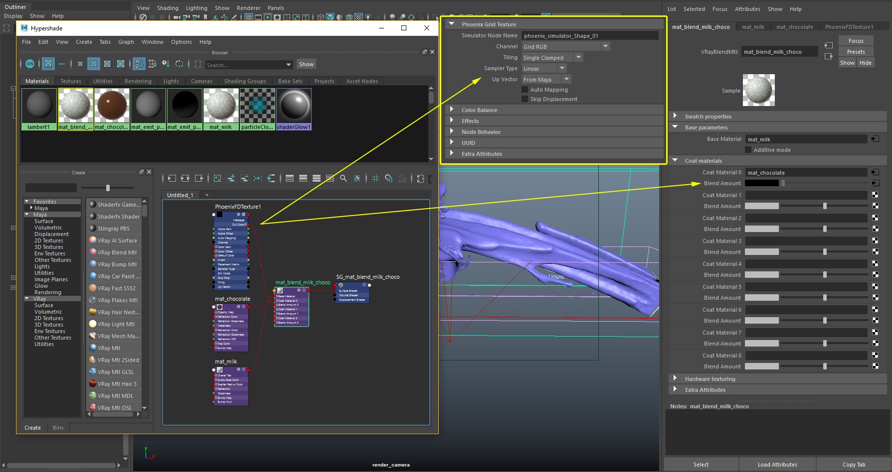
For the final Milk and Chocolate Blend material.

Assign a V-Ray Blend material to the Phoenix Simulator and rename it to mat_milk_and_choco.

Set mat_milk as the base material and mat_choco as the coat.

Assign a PhoenixFDTexture to the Blend Amount parameter.

Set the Channel parameter to RGB and provide the simulator name.

UI Text Box
typeinfo

The Grid texture loads and exposes a grid channel of a selected Phoenix Simulator object as a procedural texture. In this example, we are using it to read the RGB channel stored in the cache files of the simulator. For more information, please check the Grid Texture documentation.

Column
width60%


...


Section
Column
width40%

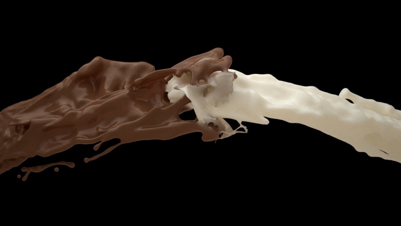
Here's a rendered image of the blend material.

The only thing left to do is to add a Rim light and a background for the final image.

Column
width60%

Image Modified


...


Section
Column
width40%

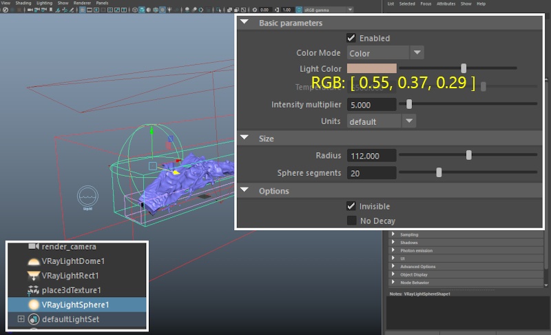
Let's add a Rim Light.

Create a Sphere Light and transform it to Translate: [ -15, 46, -178].

Set the Light Color to RGB: [ 0.551, 0.372, 0.293 ].

Set the Intensity Multiplier to 5.

The Radius is set to 112.

Options → Invisible is enabled so the light is not visible in the final image.

Column
width60%

Image Modified


...


Section
Column
width40%
UI Text Box
typetip

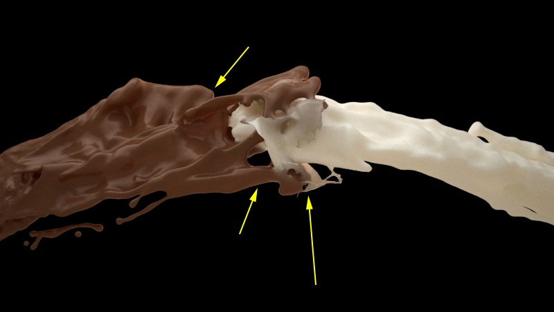
The yellow arrows in the image to the right show the effect of the Rim Light. You can see the light leaking through the milk material and the reflections on the chocolate material.

Column
width60%

Image Modified


...


Section
Column
width40%

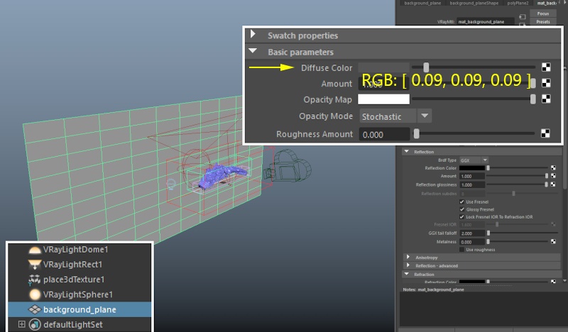
Add a Poly Plane with a Width/Height of 1800/800.

Move it to [ 0, 0, -325 ] and Rotate it to [ 90, 0, 0 ] so it's facing the camera.

Assign a new V-Ray material and set the Diffuse Color to RGB: [ 0.09, 0.09, 0.09 ].

Column
width60%

Image Modified


...


Section
Column
width40%

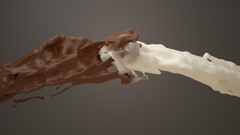
Here's the final image.

Column
width60%

Image Modified