![]()
Page History
...
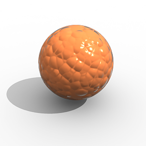
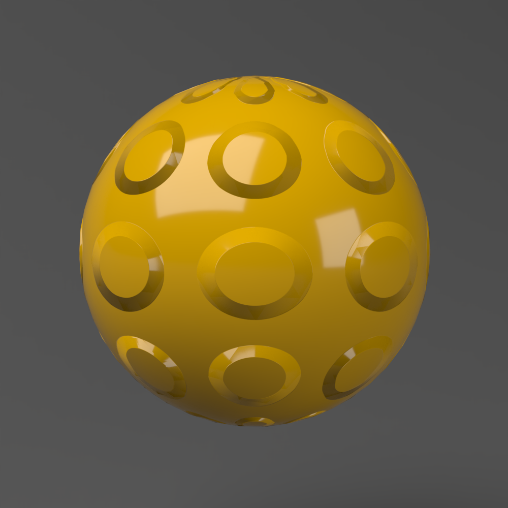
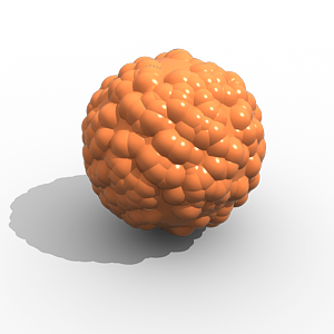
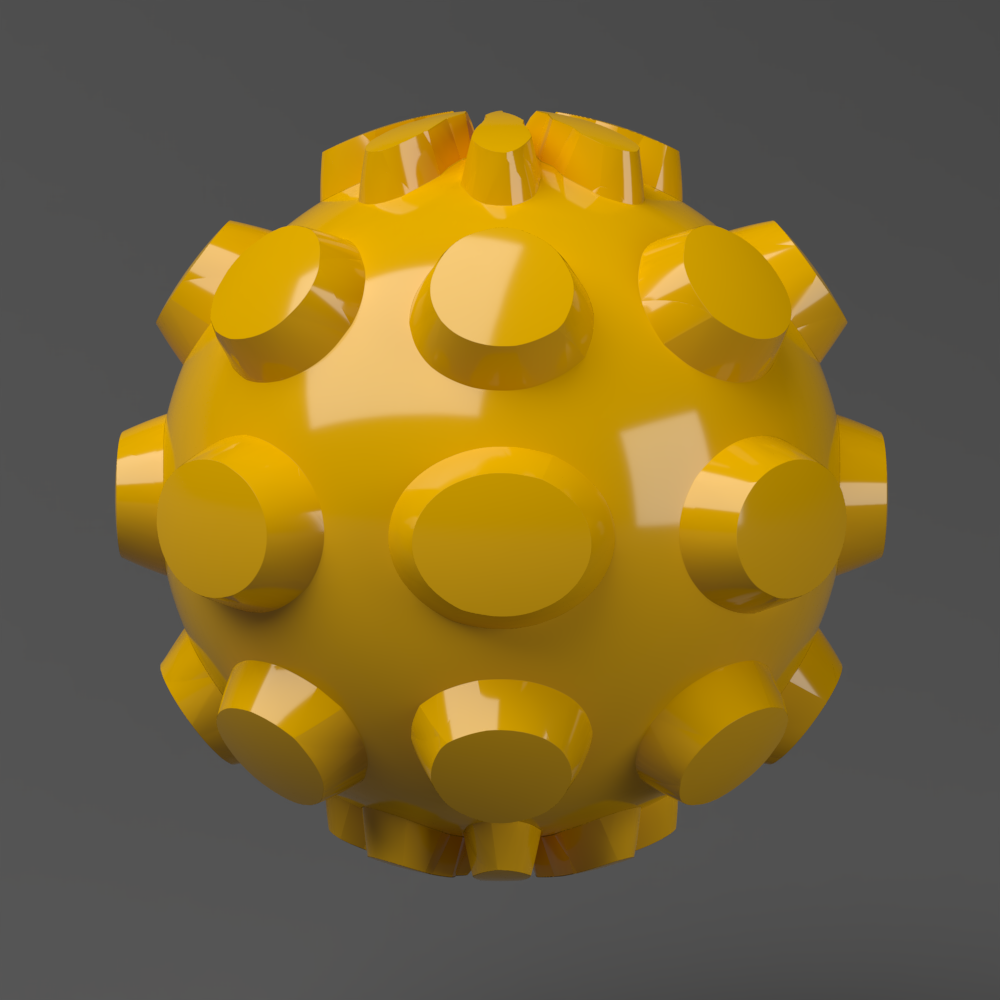
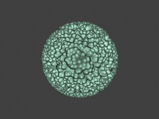
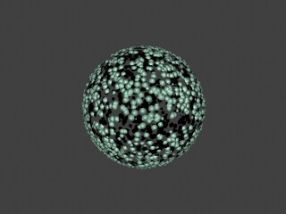
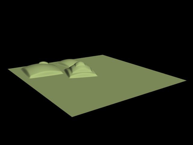
This example shows the difference between bump mapping and displacement mapping. Notice the round outline of the sphere and its shadow in the case of bump mapping, and the deformed outline produced by the displacement:
| Section | |||||||||||||||||||||||||||||||||||
|---|---|---|---|---|---|---|---|---|---|---|---|---|---|---|---|---|---|---|---|---|---|---|---|---|---|---|---|---|---|---|---|---|---|---|---|
|
...
Inputs
...
The VRayDisplacement node has two inputs:
...
| Anchor | ||||
|---|---|---|---|---|
|
...
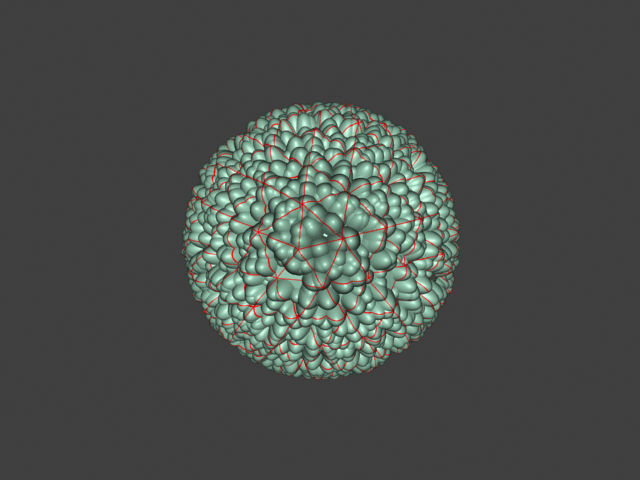
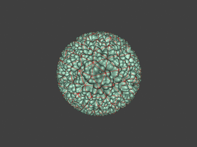
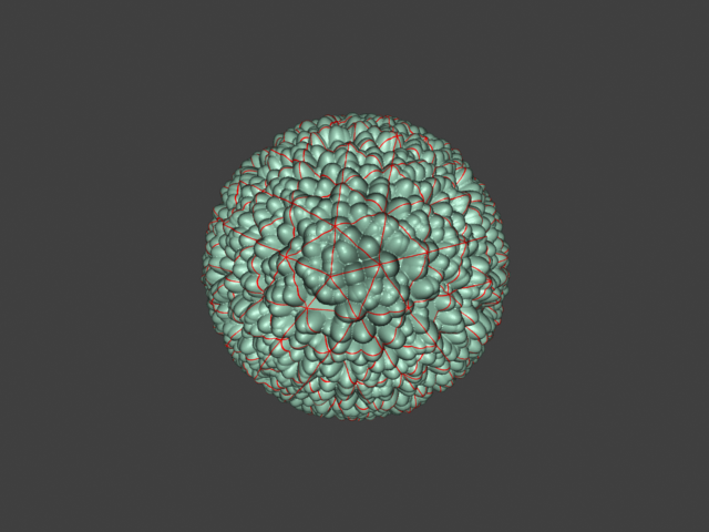
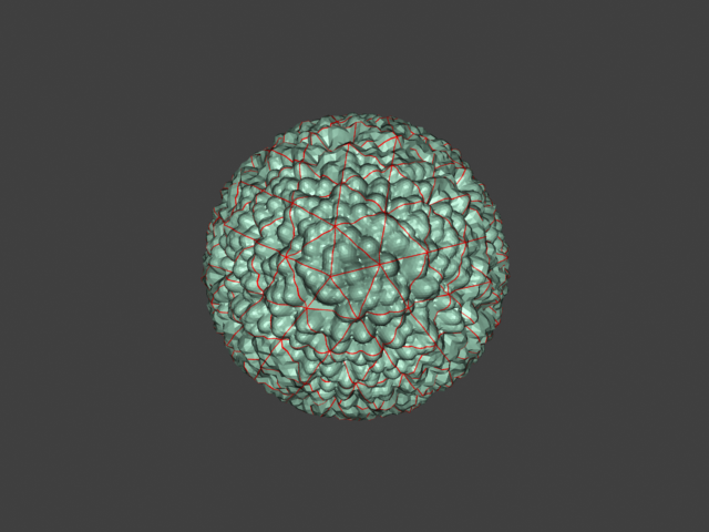
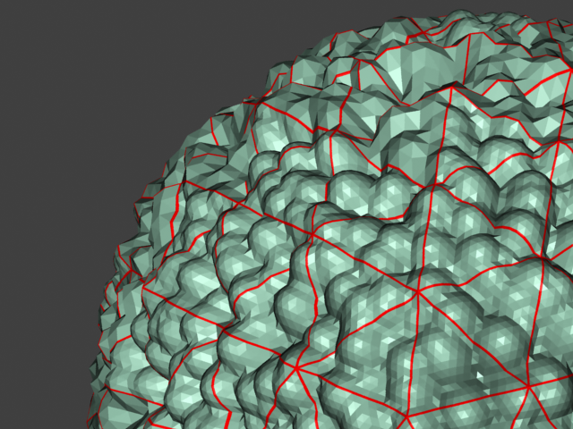
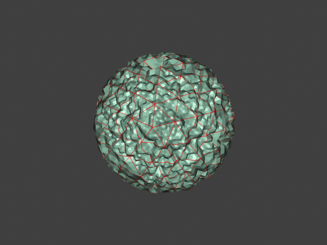
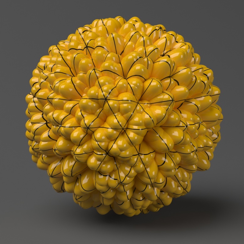
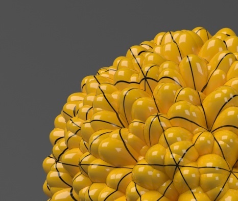
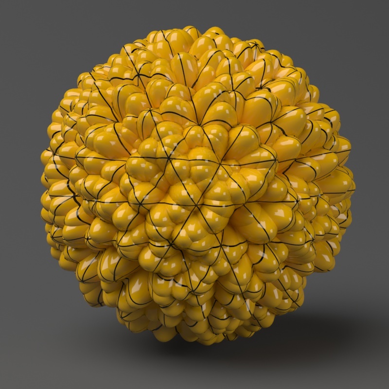
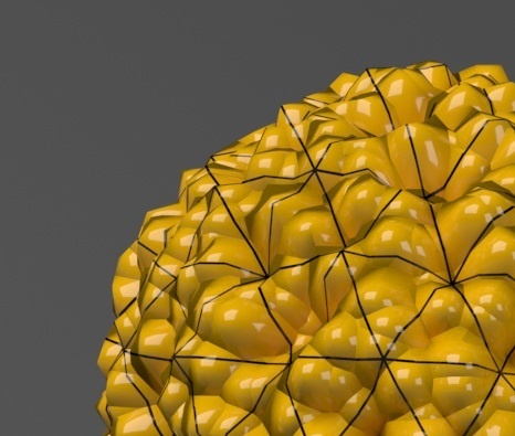
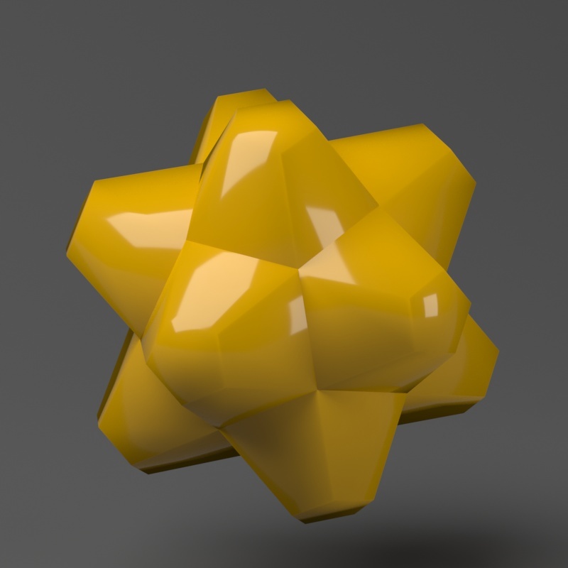
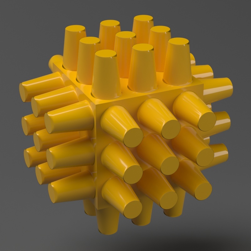
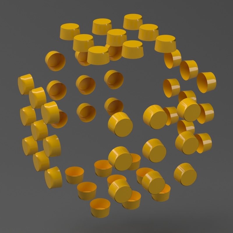
Example: Edge Length
This example shows the effects of increasing the Edge length parameter. In this example View-dependent is enabled, so Edge length is expressed in pixels. In the examples, the closeup view is a blow-up rather than a zoomed view. This means that Edge length in the closeup view refers to pixels in the original image, not the blow-up rendering. Click the images for a larger view.
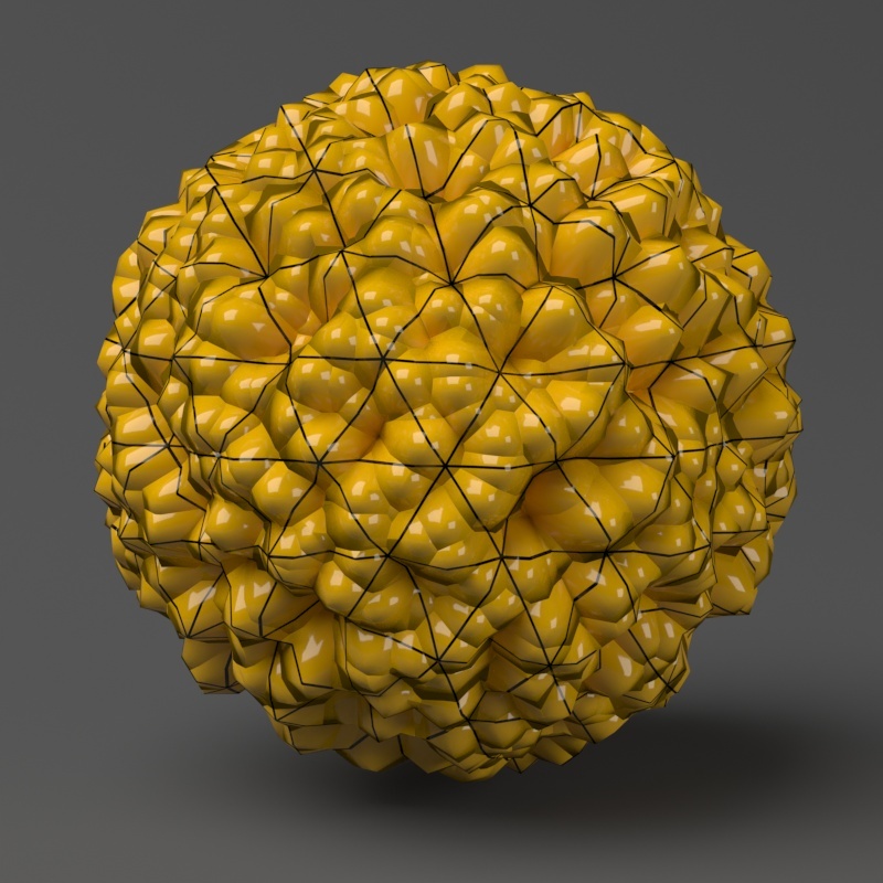
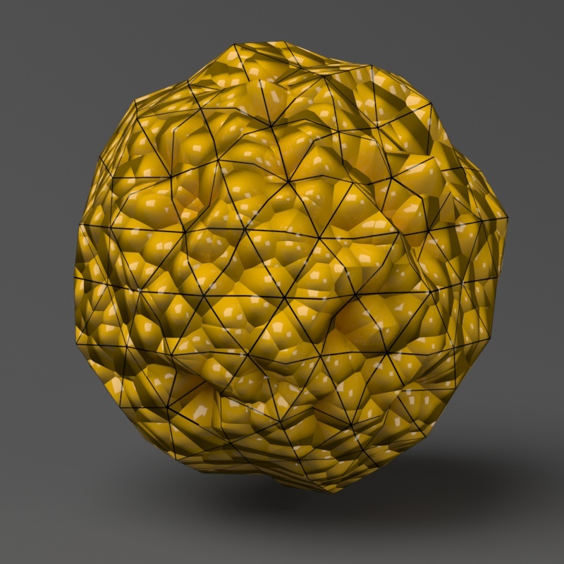
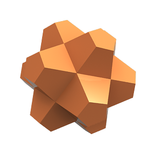
The image below was rendered
...
with a VRayEdgesTex map in the Diffuse slot of the material to show the original triangles of the mesh.
...
Additionally, we turned on the Faceted option in the VRayMtl. V-Ray
...
not only
...
smooths the surface normals, but
...
also automatically
...
applies a normals map that represents the normal of the perfect displaced surface, which
...
makes the surface look a lot more detailed than it actually is.
...
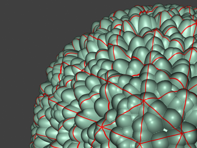
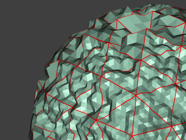
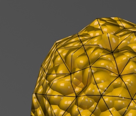
View-dependent is turned on, and it refers to pixels in the original image, not the zoomed-in image you get with a blow-up rendering. This is why we were able to do a blow-up rendering to see the individual subtriangles better. Click the images for a larger view:
...
| Section | |||||||||||||||||||||||
|---|---|---|---|---|---|---|---|---|---|---|---|---|---|---|---|---|---|---|---|---|---|---|---|
| |||||||||||||||||||||||
|

| Section | ||||||||||
|---|---|---|---|---|---|---|---|---|---|---|
|

| Section | ||||||||||
|---|---|---|---|---|---|---|---|---|---|---|
|
| Section | ||||||||||
|---|---|---|---|---|---|---|---|---|---|---|
|
|


...
Displacement Control rollout
...
Note that the Displacement Shift parameter is an absolute value in world units. If you change the Displacement Amount, you will probably need to adjust the Displacement Shift too.
...
| Section | |||||||||||||||||||||||||||||||||||||||||||||||||||||||||||||||||||||||||||||
|---|---|---|---|---|---|---|---|---|---|---|---|---|---|---|---|---|---|---|---|---|---|---|---|---|---|---|---|---|---|---|---|---|---|---|---|---|---|---|---|---|---|---|---|---|---|---|---|---|---|---|---|---|---|---|---|---|---|---|---|---|---|---|---|---|---|---|---|---|---|---|---|---|---|---|---|---|---|
|

| Anchor | ||||
|---|---|---|---|---|
|
...
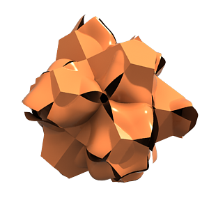
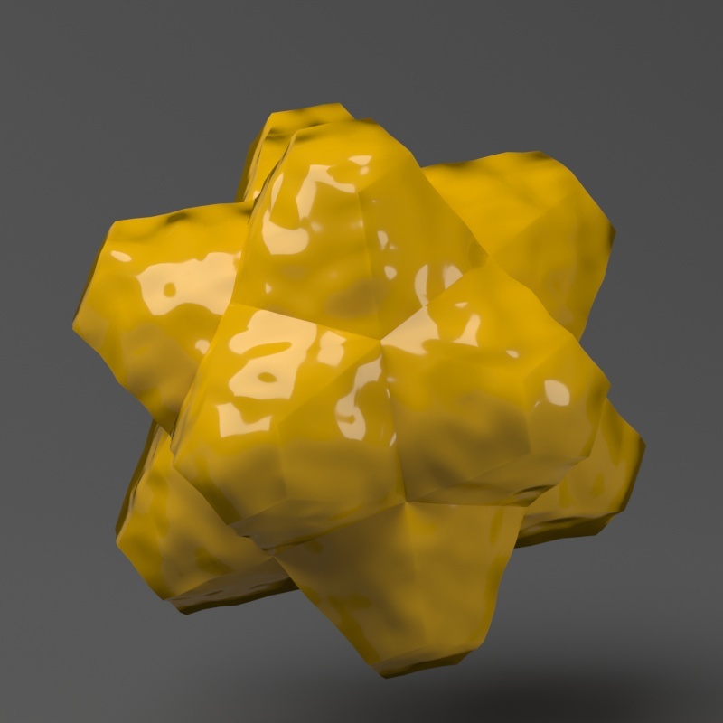
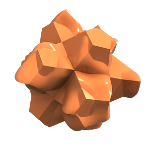
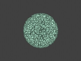
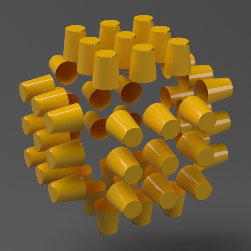
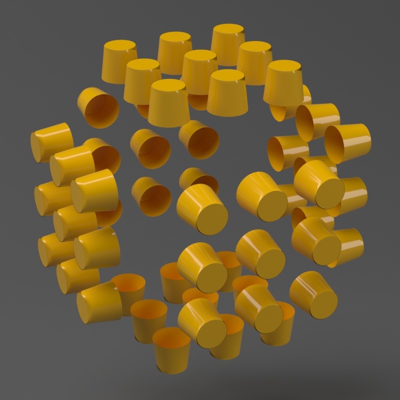
Example: Keep Continuity
The Keep Continuitycontinuity option is useful for objects with disjoint normals on neighboring triangles, usually because of different smoothing groups. In the middle image below you can see the edge splits produced by disjoint normals. Using the Keep Continuity option continuity option avoids this problem. This option will also help to produce a smoother result across material ID boundaries for objects that have been assigned Multi-Sub-Object materials.
| Section | ||||||||||||||||||||||||||||||||||||||||||||||||||||||||||
|---|---|---|---|---|---|---|---|---|---|---|---|---|---|---|---|---|---|---|---|---|---|---|---|---|---|---|---|---|---|---|---|---|---|---|---|---|---|---|---|---|---|---|---|---|---|---|---|---|---|---|---|---|---|---|---|---|---|---|
|

| Anchor | ||||
|---|---|---|---|---|
|
...
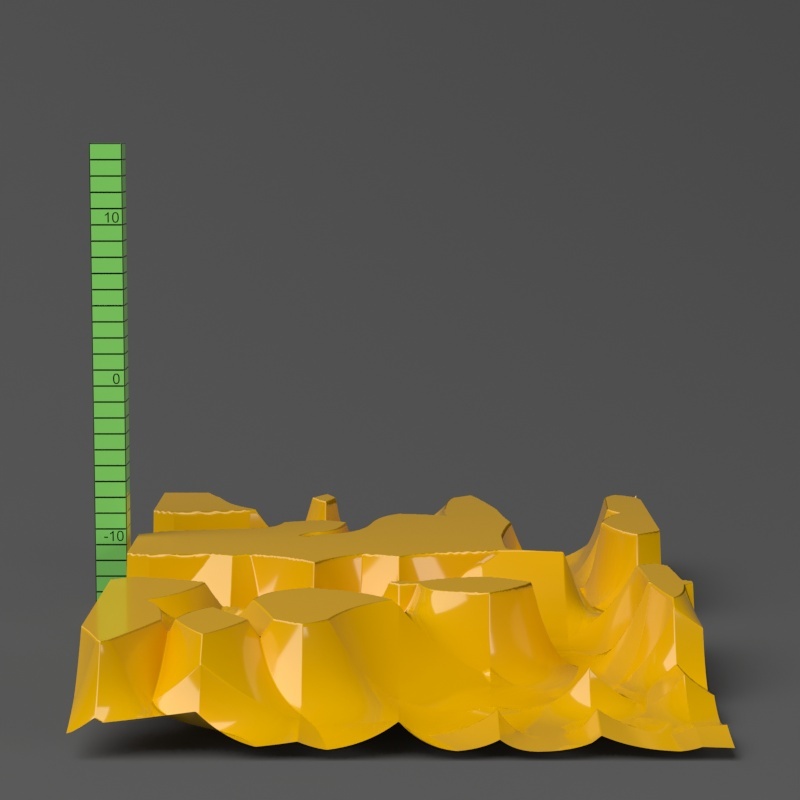
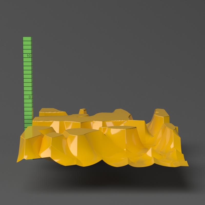
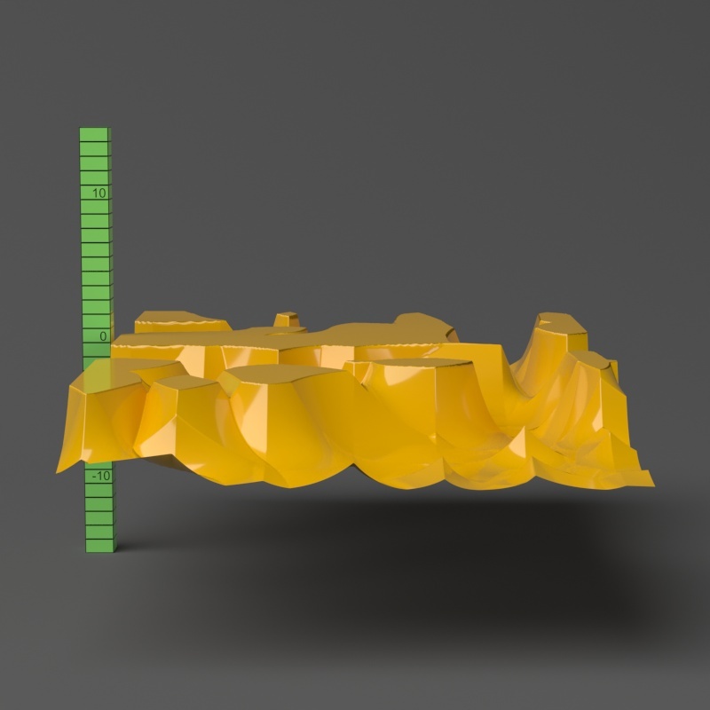
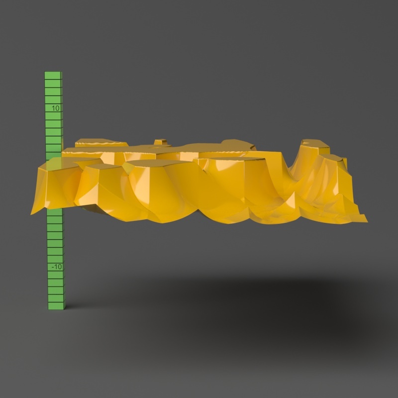
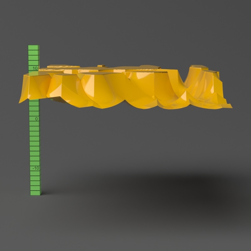
Example: Water Level
The Water Level parameter level parameter is absolute in world units. If you change the Displacement Amount and/or Displacement Shift values, you will probably need to adjust the Water Level to get the same effect. For this example, the Displacement Amount parameter is is set to 5.0 and the Displacement Shift parameter to 5.0 and Shift is set to 0.0.
...
Note that when Water level reaches Amount + Shift, all geometry is clipped.
| Section | |||||||||||||||||||||||||||||||||||||||||||||||
|---|---|---|---|---|---|---|---|---|---|---|---|---|---|---|---|---|---|---|---|---|---|---|---|---|---|---|---|---|---|---|---|---|---|---|---|---|---|---|---|---|---|---|---|---|---|---|---|
| |||||||||||||||||||||||||||||||||||||||||||||||
|


| Anchor | ||||
|---|---|---|---|---|
|
...
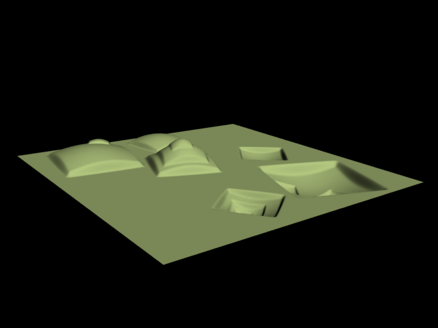
This example shows a plane mapped with a displacement map that has negative values. With the default boundaries for the displacement , (from 0 to 1) we are unable to see the geometry displaced in the negative direction. However, once we set the custom boundaries to -1 and 1 we we set Min and Max values to -1 and 1 respectively, we can see the displaced geometry in both the positive and negative direction.
| Section | |||||||||||||||||||||||||||||||||||
|---|---|---|---|---|---|---|---|---|---|---|---|---|---|---|---|---|---|---|---|---|---|---|---|---|---|---|---|---|---|---|---|---|---|---|---|
|

...