![]()
Page History
...
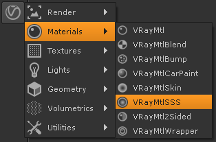
UI Path: ||Toolbar|| > V-Ray menu icon > Materials > VRayMtlSSS
General
...
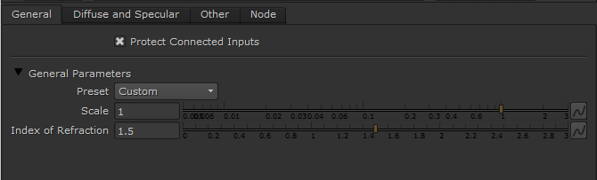
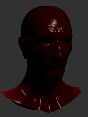
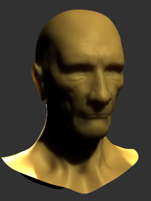
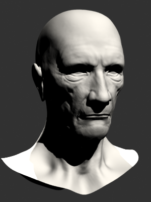
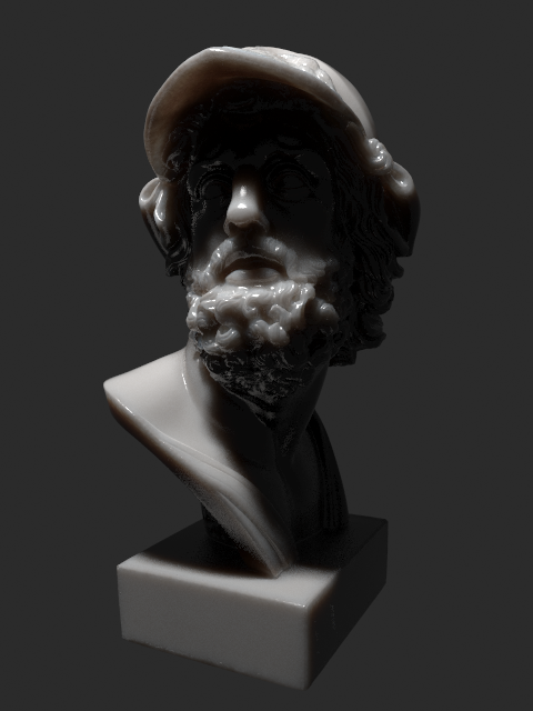
Preset – Allows you to choose one of several available preset materials. Most of the presets are based on measured data provided by by Jensen et al. in [ 3 ] in A Practical Model for Subsurface Light Transport.
Scale – Additionally scales the subsurface scattering radius. Normally, VRayMtlSSS will take the scene units into account when calculating the subsurface scattering effect. However, if the scene was not modeled to scale, this parameter can be used to adjust the effect. It can also be used to modify the effect of the presets, which reset the Scatter radius parameter when loaded, but leave the Scale parameter unchanged. For more information, see the Scale example below.
Index of Refraction – The index of refraction for the material. Most water-based materials like skin have an index of refraction of about 1.3.
...
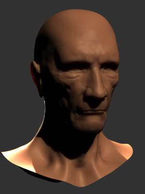
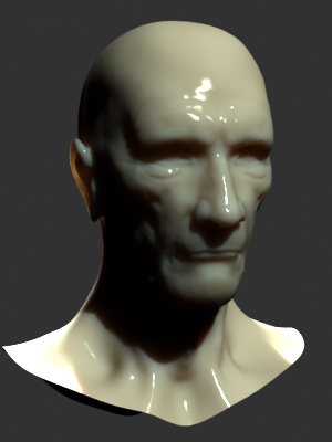
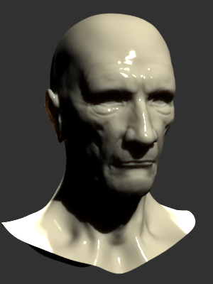
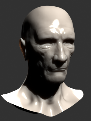
Example: VRayMtlSSS Presets
| Section | ||||||||||
|---|---|---|---|---|---|---|---|---|---|---|
|
| Section | ||||||||||
|---|---|---|---|---|---|---|---|---|---|---|
|

| Anchor | ||||
|---|---|---|---|---|
|
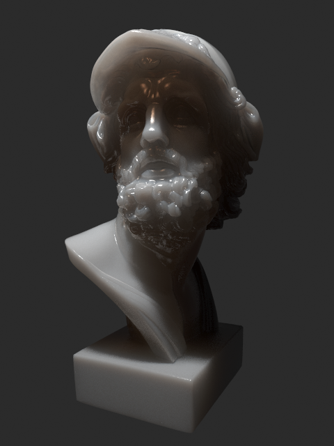
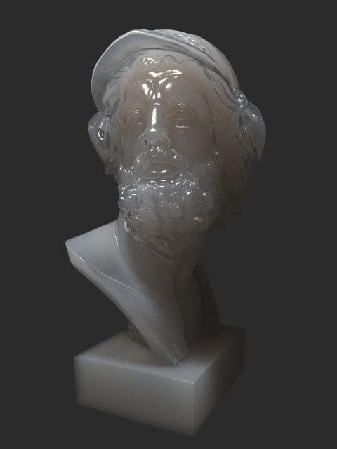
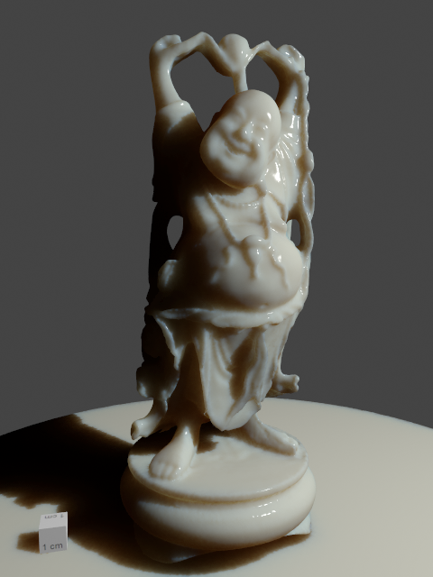
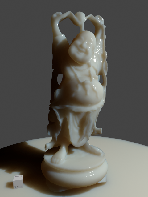
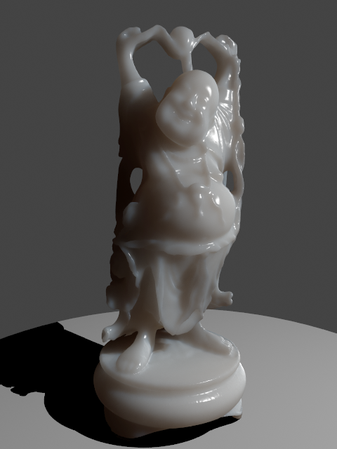
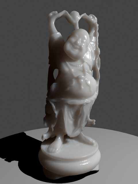
Example: Scale
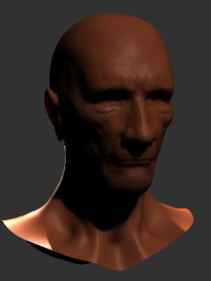
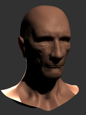
This example shows the effect of the Scale parameter. Note how larger values make the object appear more translucent. In its effect, this parameter does essentially the same thing as the Scatter radius parameter, but it can be adjusted independently of the chosen preset. The images are rendered without GI to better show the sub-surface scattering. The Single scatter parameter was set to Raytraced (solid). The Marble (white) preset was used for all images.
| Section | ||||||
|---|---|---|---|---|---|---|
|
Diffuse and SSS Layers
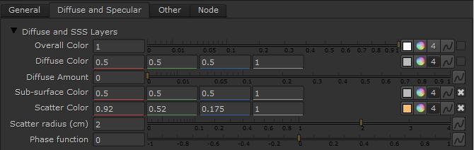
Overall Color – Controls the overall coloration for the material. This color serves as a filter for both the diffuse and the sub-surface component.
Diffuse Color – The color of the diffuse portion of the material.
Diffuse Amount – The amount for the diffuse component of the material. Note that this value in fact blends between the diffuse and sub-surface layers. When set to 0.0 , the material does not have a diffuse component. When set to 1.0 , the material has only a diffuse component, without a sub-surface layer. The diffuse layer can be used to simulate dust etc. on the surface.
Sub-surface Color – The general color for the sub-surface portion of the material. For more information, see the Sub Surface Color example below.
Scatter Color – The internal scattering color for the material. Brighter colors cause the material to scatter more light and to appear more translucent; darker colors cause the material to look more diffuse-like. For more information, see the Scatter Color example below.
Scatter radius (cm) – Controls the amount of light scattering in the material. Smaller values cause the material to scatter less light and to appear more diffuse-like; higher values make the material more translucent. Note that this value is specified always in centimeters (cm); the material will automatically take care to convert it into scene units based on the currently selected system units. For more information, see the Scatter Radius example below.
Phase function – A value between -1.0 and 1.0 that determines the general way light scatters inside the material. Its effect can be somewhat likened to the difference between diffuse and glossy reflections from a surface, however the phase function controls the reflection and transmittance of a volume. A value of 0.0 means that light scatters uniformly in all directions (isotropic scattering); positive values mean that light scatters predominantly forward in the same direction as it comes from; negative values mean that light scatters mostly backward. Most water-based materials (e.g. skin, milk) exhibit strong forward scattering, while hard materials like marble exhibit backward scattering. This parameter affects most strongly the single scattering component of the material. Positive values reduce the visible effect of single scattering component, while negative values make the single scattering component generally more prominent. For more information, see the Phase Function example and the Phase Function: Light Source example below.
| Anchor | ||||
|---|---|---|---|---|
|
...
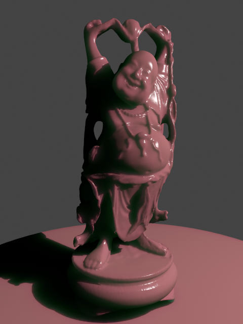
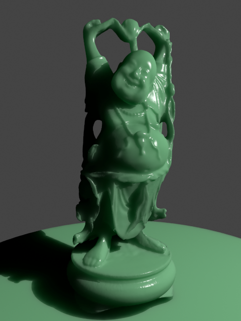
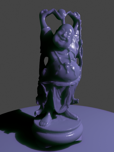
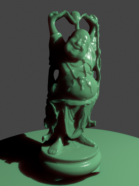
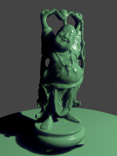
Example: Sub Surface Color
This example and the next demonstrate the effect of and the relation between the Scatter color and the Sub-surface color parameters. Note how changing the Sub-surface color changes the overall appearance of the material, whereas changing the Scatter color only modifies the internal scattering component.
The Scatter color is set to green.
| Section | ||||||
|---|---|---|---|---|---|---|
|
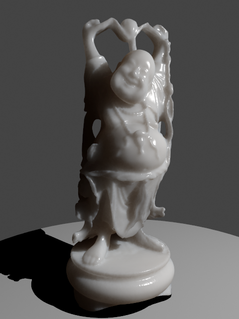
Note: the "happy buddha" model is from the Stanford scanning repository (http://graphics.stanford.edu/data/3Dscanrep/).
...
| Anchor | ||||
|---|---|---|---|---|
|
...
Example: Scatter Color
The Sub-surface color is kept to green.
...
| Section | ||||||
|---|---|---|---|---|---|---|
|

Note: the "happy buddha" model is from the Stanford scanning repository (http://graphics.stanford.edu/data/3Dscanrep/).
...
| Anchor | ||||
|---|---|---|---|---|
|
...
Example: Scatter Radius
This example shows the effect of the Scatter radius parameter. Note that the effect is the same as increasing the Scale parameter, but the difference is that the Scatter radius is modified directly by the different presets.
...
The cube in the lower left corner has a side of 1cm.
...
| Section | ||||||
|---|---|---|---|---|---|---|
|

Note: the "happy buddha" model is from the Stanford scanning repository (http://graphics.stanford.edu/data/3Dscanrep/).
| Anchor | ||||
|---|---|---|---|---|
|
...
...
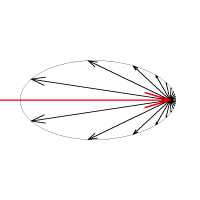
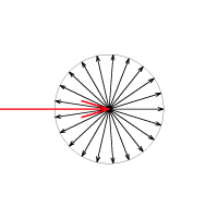
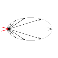
Example: Phase Funciton
...
This example shows the effect of the Phase function parameter. This parameter can be likened to the difference between diffuse reflection and glossy reflection on a surface, however it controls the reflectance and transmittance of a volume. Its effect is quite subtle, and mainly related to the single scattering component of the material.
The red arrow represents a ray of light going through the volume; the black arrows represent possible scattering directions for the ray.
| Section | ||||||
|---|---|---|---|---|---|---|
|
| Section | ||||||
|---|---|---|---|---|---|---|
|
Note: the "happy buddha" model is from the Stanford scanning repository (http://graphics.stanford.edu/data/3Dscanrep/).
...
| Anchor | ||||
|---|---|---|---|---|
|
...
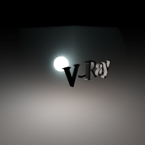
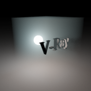
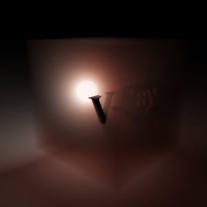
Example: Phase Function: Light Source
...
| Section | ||||||
|---|---|---|---|---|---|---|
|
...
Specular Layer Parameters
...
Note: the "happy buddha" model is from the Stanford scanning repository (http://graphics.stanford.edu/data/3Dscanrep/).
...
| Anchor | ||||
|---|---|---|---|---|
|
...
...
| Fancy Bullets | ||||||
|---|---|---|---|---|---|---|
| ||||||
Here is a list of links and references used when building the VRayMtlSSS material.
|