![]()
Page History
This page contains information on how Phoenix simulations work internally. Steps for setting up a simulation can be found on the Getting Started with Phoenix FDthe QuickStart Guides page.
How does Phoenix's fluid solver work?
...
Phoenix's fluid simulation calculates how a fluid would evolve during a period of time. While you might be familiar with the term fluid as meaning "liquid", in physics the term fluid refers to both liquids and gases. When this documentation refers to a fluid, it means liquid or fire/smoke. The simulation runs in sequential steps, and at each step the fluid is calculated a little further in time ahead of the previous step. This way each new step depends on the previous step, and a new step cannot start before the last one has already finished. This is one of the biggest differences between distributed rendering and distributed simulations - e.g. if you want to simulate 100 frames, you can not run frames 1-50 on one machine and frames 51-100 on another machine simultaneously.
The result of each simulation step is a velocity field - i.e. the fluid simulation calculates the speed and direction of the movement of the fluid in different points in space. In order to visualize the effect, a simulation can also transport visible fields, such as smoke density, temperature, and also different kinds of particles along the velocity field that gets simulated. The two most important processes in a simulation are Advection - how the fluid moves through space, and pressure solve, called Conservation in Phoenix - which is basically the step that makes simulated fluids behave like real-world fluids - swirling, rolling and creating plumes. Both of these options are controlled from the Dynamics rollout of the Phoenix Simulators.
In order to see the effect of the fluid simulation, a A fluid simulation can also transport visible fields, such as fields along the simulated velocity field. Such fields can be smoke density, temperature, and also different kinds types of particles along the velocity field that gets simulated, etc. The velocity field is the raw result of the fluid simulation and by default it's invisible, but these additional channels make the fluid motion visible. You can enable these fields for simulation from the Output rollout and then actually create them in the simulation container using Sources, or other more advanced methods.
...
While the simulation runs, it's in the background, and the user interface of 3ds Max remains active. You can change many simulation parameters (except for a few initial core parameters) during the simulation and see how they affect it. Rendering is also enabled during simulation, so you don't have to wait until the end of the simulation to render images and see how the simulation looks and fits into the scene.
Particle and Grid-based Simulation
...
There are two main approaches used in simulation systems:
...
A third hybrid method between particle and grid simulations are the FLIP simulations, which Phoenix uses for liquids. FLIP simulations take the best from both worlds and produce much realistic liquid effects quickly. FLIP liquid simulations were first added in Phoenix 3.0. Before that, liquid were simulated using the grid solver. In Phoenix 3, you can still open and simulate older scenes saved from Phoenix 2 using the old grid liquid solver. Note that Phoenix uses pure particle simulation for the secondary particle systems such as Foam, Splash, WetMap and Mist as these are simpler and don't suffer from issues that liquids in pure particle or grid simulations have, such as having to maintain volume and not collapse on themselves if put in a large container.
Fire/Smoke vs. Liquid Simulation
...
Simulations performed by Phoenix FD can Phoenix can be roughly divided into two major categories:
...
These categories are for convenience only, and are not rigid. Once you've created a few basic simulations and have become more familiar with Phoenix FD, you will have a better grasp of how the tools work, and when creating an effect that is not strictly fire or liquid you'll know how to represent it most efficiently. For example, sparks embers or thin smoke might seem to fall into the "fire" category, but in practice these effects might be better served by particles and thus could use some of the tools designed for liquids.
Simulation and Rendering
...
The results from Phoenix simulations are saved to cache files. After that, Phoenix can read this cache data for quick viewport preview, or for rendering. Fire/smoke simulations usually produce grid voxels and can additionally produce particles that accompany and enrich the fire/smoke effect. Liquid simulations mainly produce particles and Phoenix can also automatically convert them to voxels when saving cache files during simulation.
...
Particle data is rendered by connecting a Particle Shader to the Simulator, and you can also use the Particle Shader to render standard particle systems that don't come from Phoenix. The Particle Shader is quite versatile and can draw particles as points, bubbles, or could also voxelize particles into a grid and render that as fog using the volumetric shader - this is how you can render mist from a waterfall, for example.
...
| Anchor | ||||
|---|---|---|---|---|
|
How to Set up a Simple Simulation
...
Phoenix FD comes Phoenix comes with a toolbar that contains ready Quick Setup presets for commonly used fluid simulations.
...
At this stage, the setup is ready. To begin the simulation, go to the "Simulation" rollout of the simulator and press start.
Simulation
...
The simulation is performed in a box (called a grid) divided into small cells that contain the fluid's properties at their coordinates (temperature,velocity etc...). The minimal setup of the simulation core includes velocity and temperature as fluid properties of the fire/smoke simulation or velocity and liquid density for the liquid simulator, respectively. Depending on the core settings, one or more additional channels can be added and will be dragged along the fluid. These additional channels are:
...
The RGB channel does not affect the simulation; it's just a helper channel that can be used in the rendering for texture mapping or directly as RGB value. The Wavelet channel must be exported only when wavelet turbulence must be applied to the simulation on a second pass. Particle ID channel is helpful to identify the same particle between the frames.
| Anchor | ||||
|---|---|---|---|---|
|
...
The core recalculates the grid content repeating three main actions:
...
Depending on the core settings, one or more additional operations can be included in the process. These operations are:
| Fancy Bullets | ||
|---|---|---|
| ||
| Anchor | ||||
|---|---|---|---|---|
|
...
The burning process requires Fuel and Smoke as additional channels (they will be included automatically). Like in the real world, the burning process converts the fuel into smoke and produces some heat which expands the fluid. There is no separate channel for oxygen, however it is taken into consideration using the smoke and the fuel to be calculated. The relation is oxygen=1-fuel-smoke. The energy of the fuel controls how much heat will be produced and the inflation/expansion rate controls how fast the ignition will propagate.
For convenience the second parameter is just called "Propagation", but advanced users should keep in mind that the real meaning of the parameter is inflation/expansion rate.
| Anchor | ||||
|---|---|---|---|---|
|
...
The vorticity confinement keeps the small turbulences alive. It's natural for grid fire/smoke fluid solvers to lose fine details both in the density and in the velocity of simulations. Vorticity Confinement is a method for bringing these small details back and making the fluid more turbulent. However, classic vorticity tends to overcompensate and tear the fluid up too much, breaking the large-scale rolling of smoke and fire. In such cases, Phoenix's Massive Vorticity comes in handy - it does not allow the fluid to go wild and completely lose its shape and works well for both quick and slow moving fluids.
| Anchor | ||||
|---|---|---|---|---|
|
...
By default, the grid and particles in a simulation interact with scene objects. For example, in a liquid simulation, the liquid will bounce off or flow around any geometry it encounters.
There are three types of external objects that can interact directly with the simulator:
| Fancy Bullets | ||
|---|---|---|
| ||
In every simulation step, all the nodes in the scene are enumerated and processed whether or not they belong to one of the above mentioned groups and have permission to interact with the simulator.
| Anchor | ||||
|---|---|---|---|---|
|
...
All geometry objects in the scene are considered to be rigid bodies. They can affect the simulation in three different ways:
...
Another Phoenix simulator can also be used as Rigid body. In this case, the Surface Channel is used to determine the surface.
| Anchor | ||||
|---|---|---|---|---|
|
...
The particles can interact directly with the simulation only as sources, depending on the Emit Mode (Volume Inject or Volume Brush) of the Fire Source | PHXSource. The velocity of the injected fluid is the velocity of the particle, which allows the fluid to be involved in the particles' motion.
| Anchor | ||||
|---|---|---|---|---|
|
...
The forces change the velocity of the fluid in two different ways:
...
Resimulation
...
Resimulation is the process of simulating over an existing simulation, which is called a base simulation. The base simulation must be processed first, and its Velocity channel must be exported. Then, to enable the resimulation, the Enable option in the Resimulation rollout must be checked. While this option is enabled, the simulator works in resimulation mode (i.e. all simulator functionality is now related to the resimulation).
...
| Fancy Bullets | ||
|---|---|---|
| ||
|
Rendering
...
| Anchor | ||||
|---|---|---|---|---|
|
Phoenix FD registers itself as a global environment volumetric, except when working in Geometry Mode. The global volumetric takes care to blend properly all Phoenix instances in the scene (simulators and foam/splashes). However for overlapping with other volumetrics, geometry mode is recommended.
Channels, Diagrams and Gradients
...
After the simulation, cache files containing the exported physical channels are produced. In the real world, the connection between the physical quantities and the visual appearance is well-defined. However, for more flexibility in Phoenix FD, the user is allowed to choose how the render elements depend on the physics. For example, in the real world, the temperature determines the emissive color; however, in Phoenix FD, the velocity can be set to determine the emissive color instead of the temperature. The physical channel used to determine any given render element is called a source, and the dependence between the physical quantity and the render element is determined by tables called palettes. For the rendering of the volumetric content, three render elements are calculated for each point: emissive color, diffuse color, and opacity (alpha). To calculate each of them, the shader performs the following steps:
...
The control over the above mentioned process is arranged in Render Fire, Render Smoke Color, and Render Smoke Opacity rollouts where the user can choose the source and the palette for each channel. For the emissive color, both a diagram and a gradient are used, because–as opposed to the diffuse color–it can be outside the range 0-1. When this happens, the gradient will appear saturated. For each render element, the user is also allowed to select a texture map as the source channel. In this case, the palette is skipped and the sampled color is used directly.
Smoke Opacity vs. Fully Visible Shading
...
There is a well-defined connection between the transparency and the emissive light in the real world. For smoke (diffuse light), the connection is pretty clear and everyone has intuitive sense of how it works. For the emissive light, however, most of the people will give the wrong answer when asked, "Is a smokeless fire fully transparent?" The common, yet wrong, answer is, "Yes it is. If there is no smoke, the flame is fully transparent and will cast no shadows." However, the correct answer is "No, the fully transparent gases cannot emit any light, even if they are hot enough." This is why acetylene flame is less bright than a candle, despite its higher temperature. It just produces less smoke. However, this way of shading can seem strange and inconvenient, because there is no clearly separated control over the smoke and flame. Be careful when trying to achieve denser smoke, because the result can be an undesired brighter flame. For this reason, Phoenix FD provides different modes of shading: physical and detached. This is controlled by the Fire Opacity Mode parameter in the Fire rollout. In Fully Visible mode, the emissive part is fully independent of the transparency and you are not obligated to keep in mind the aforementioned connection. In Use Smoke Opacity mode, the smoke's alpha controls the Fire's opacity. There is also the Use Own Opacity mode where the fire has a separate opacity curve that can be adjusted independently from that of the smoke.
| Anchor | ||||
|---|---|---|---|---|
|
...
Some rendering techniques (like solid rendering, displacement, etc.) require a separate channel to work with, and for this reason the Surface channel is provided. Most of them use the Surface channel to calculate an implicit surface from its content, using the following rule: all the points with a value above given threshold will lie inside the surface and all the points with a value below the threshold will lie outside the surface. The Mesh Mode gives the best look over the whole concept, because it makes the surface visible.
| Anchor | ||||
|---|---|---|---|---|
|
...
Volumetric Geometry Mode
...
In this mode, the appearance of the content is exactly like in the the Volumetric Mode, except for the ability to blend with other overlapping volumetric objects. However, it is slower to render and takes more memory. Also it requires the Max. transp levels in the the Global Switches rollout in the V-Ray Render Settings to be increased.
Volumetric Heat Haze Mode
...
This mode is used to achieve mirage effects and heat haze. In this mode, the ray traced in the volume changes its direction at each step according to the content of the Surface Channel. It may appear that this mode is similar to pure geometry mode, but it is not. The shading is more similar to a V-Ray refractive material than the shading in volumetric mode or pure geometry mode. As with the shading of refractive materials, the alpha is set to 1 for the rays intersecting the simulator's grid.
Anchor SolidMode SolidMode
Mesh Mode
| SolidMode | |
| SolidMode |
...
This mode produces a solid object with a sharp surface, determined by the Surface channel, and can be shaded using any material.
Adding Fine Details
...
There are two direct methods that can be used to add fine details in the shading. In order to enhance the realism of the movement of small details in the fluid, V-Ray comes with a Particle Texture called Particle Texture. When used in combination with a particle system driven by a Phoenix Simulator, the particle texture is capable of properly animating the small details along the fluid surface.
Texture Modulation
...
This is the common way used in the fluid systems to add fine details. In the Render Fire, Render Smoke Color and Render Smoke Opacity rollouts is a parameter called Modulate near the texture slots for each render element. When enabled, the corresponding render element will be multiplied by the value of the texture map, except in the case when a texture is selected as the source channel.
| Anchor | ||||
|---|---|---|---|---|
|
...
This technique is more sophisticated than texture modulation and produces a significantly better result. The idea of displacement is similar to the usual geometry displacement, where the surface is displaced along its own normals at a distance determined by a texture map. The nearest point of the surface as specified by the Surface channel determines the direction for the displacement.
...
Surface Driven vs. Volumetric Displacement
...
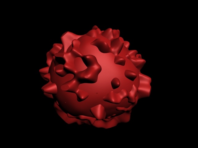
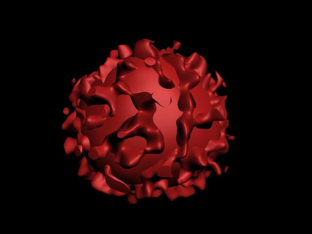
The displacement in Phoenix FD works Phoenix works by shifting the point of sampling with an offset, the direction of which is determined by the gradient of the effects channel while the distance is determined by the brightness of a given map. There are two different modes used to sample the aforementioned map, switched by a checkbox in the rendering rollout. If the checkbox is NOT checked, the map is sampled at the point of shading, and we call this "volumetric displacement". If the checkbox is checked, the coordinates are first projected over the surface as determined by the effects channel. The point of projection is then used as map coordinates. We call this "surface driven displacement." Surface driven displacement is slower and requires some initial calculations, but it keeps the topology of the iso-surfaces. Volumetric displacement is faster, but tends to produce island-like formations if the displacement value is too big. Beside performance, volumetric displacement has one more important advantage: it does not require the distinct surface of the effects channel. Therefore, it will work fine in scenes where surface-driven displacement produces flickering.
Example: Surface Driven vs. Volumetric Displacement
...
| Section | ||||||||||||||||||||
|---|---|---|---|---|---|---|---|---|---|---|---|---|---|---|---|---|---|---|---|---|
|
Foam and Splashes
...
The PhoenixFD solution Phoenix solution for creating foam and splashes is particle based and is achieved by two relatively separate features - a foam/splashes particle simulator and a foam/splashes particle shader. The particle simulator is embedded in the PhoenixFD Phoenix Simulator node and exports its content via PhoenixFDPGroup nodes, supporting position, velocity, size and id channels. The particle shader is designed as a separate component: Particle Shader. This component can render PhoenixFDPGroup and any standard particle system that exports position, size and velocity channels.
| Anchor | ||||
|---|---|---|---|---|
|
...
Phoenix Simulator
...
There are several particle types that the PhoenixFD Phoenix Simulator exports:
| Fancy Bullets | ||
|---|---|---|
| ||
|
The birth of particles can be performed automatically (for foam and splashes) by a user source (see Fire Source) or by a script. When automatic birth is used, the simulator calculates a "birth potential" for each cell and compares this potential with the birth threshold set by the user. If the potential is above the threshold, the simulator creates new particles in the quantity specified in the "birth rate" parameter, in thousands per cubic scene unit. Both foam and splashes are born in this way; the only difference is how the "birth potential" is calculated. Additionally, when a splash particle hits the water surface, foam is automatically created.
The simulation of the particles is very different for each type. The simplest one is the "drag". This type of particle simulation generates particles that are just dragged with the fluid. This is much like the PhoenixFDForce operator for the standard particle systems but much more efficient: you can drag a million particles in few minutes. The second type (by complexity) is the splashes type. The splashes are just left in free fall until they hit some object or the water surface. The free fall is not the simplest one, it is affected by the movement of the air (do not forget that Phoenix simulates the air too, not just the liquid!) and the air-splashes interaction is controlled by the air friction parameter. The most complicated type is foam. The foam particles interact not only with the fluid, but with each other as well. This interaction produces a repulsive force when the particles are too close, and an attractive force when they are not, ensuring the foam's consolidation. This process is the most expensive one and is controlled by the B2B interactionFoam Volume parameter. When only surface foam is needed, the aforementioned process can be switched off by setting the parameter to zero.
| Anchor | ||||
|---|---|---|---|---|
|
...
The Particle Shader node can render the particle systems in several different ways - as separate bubbles/droplets, as points, or as fog. In fog mode, the bounding box of all particles is calculated and a grid based shader is constructed using the bounding box and the fog resolution parameter. This mode is most suitable for surface foams, when the grid height is relatively large and the particle count is huge. The other mode (particle-based shading) is more complicated and interesting; it allows us to achieve a larger variety of effects. One reasonable question about this mode is why we need it, when one can render each particle as geometry with the proper material instead. There are several advantages, but the most important one is the ability to convert the scattering into diffuse color, which gives the natural bright appearance of the foam and the splashes. Another important advantage is cellular mode, which allows shading of close-up foam.
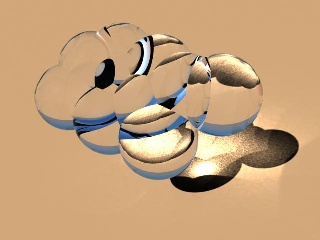
There are three different modes of shading for spherical particles - bubbles, cellular, and splashes. In each mode, a particle is represented as a sphere with a radius equal to its size and with certain optical properties. The "bubble" and "cellular" modes are intended for foam rendering and have the same optical properties of the surface. They differ in the geometry representation only - bubble mode uses simple spheres, whereas cellular mode builds polyhedron-like cells, similar to real foam. The cell walls are not flat, but slightly curved, which provides a more realistic appearance.
Example: Rendering of Foam and Splashes
...
| Section | |||||||||||||||||||||||||
|---|---|---|---|---|---|---|---|---|---|---|---|---|---|---|---|---|---|---|---|---|---|---|---|---|---|
|
...