![]()
Page History
Overview
...
The rendering process in Chaos Phoenix FD is separated from the simulation , but process, because simulated caches contain only simulation data, and no render settings.
However, for ease of operation is performed by the same object that performs the simulation. However, this is only true for the use, the Liquid Simulator object also contains a Rendering rollout, which provides flexible options for rendering the simulator grid's content, not for the particles contained in the cache file. If you want to render the secondary effect particles (foam, splashes, or drag particles), create a Particle Shader object and connect it to the simulator.
The Rendering rollout offers multiple render modes, that can be divided into two types: Surfaces and Volumetric.
| UI Text Box | size | medium|
|---|---|---|
| ||
If you want to render the particle content of the Simulator (e.g. foam, splashes, or drag particles), create a Particle Shader | PHXFoam object and add the simulator to it. |
Phoenix FD is able to operate in multiple rendering modes that can be divided into two main branches: volumetrics and surfaces. The volumetric modes are used for fire and smoke. 3ds Max materials can't be used to shade volumetrics, so their shading is described in the Fire and Smoke color rollouts.
The liquid surface of a PhoenixFD simulation is generated from the Liquid Particles. The particles are converted into a mesh and shaded by the material assigned to the simulator object. This section contains the controls for this meshing process.
| |
Liquid simulations are typically rendered using one of the surface render modes. Meanwhile, volumetric modes are typically used for rendering fire and smoke. |
Surface render modes generate a mesh surface, which is based on the channel specified in the Surface Channel parameter.
This is especially useful for liquid simulations, where by default, the Grid Liquid Channel is exported during simulation, which enables the simulator to voxelize Liquid Particles into a Grid Channel. This way, Liquid Particles can be used to indirectly generate a liquid surface, that can be rendered as a mesh using one of the surface render modes, such as Mesh, Isosurface, Cap Mesh or Ocean Mesh.
The meshed liquid then behaves just like any regular geometry, meaning you can assign 3ds Max or V-Ray materials to the Simulator, and there is no need for a dedicated shader. The Rendering rollout also contains additional controls for this meshing process, to customize the appearance of the surfaceAdvanced control over the shading is provided with the PhoenixFDTexture which can be used to drive the properties of a V-Ray material applied to a liquid surface. For Volumetric rendering, Phoenix FD provides you with the ability to drive the color and opacity of Fire / Smoke simulations through any of the supported channels (such as Smoke, Speed, RGB, etc.), as long as they are present in the cache files.
| UI Text Box | size | medium|
|---|---|---|
| ||
UI Path: ||Select Liquid Simulator | LiquidSim object|| > Modify panel > Rendering rollout |
Actions
Render Presets... – Opens a menu for loading and saving different presets. The following options are available:
| Fancy Bullets | ||
|---|---|---|
| ||
|
Parameters
...
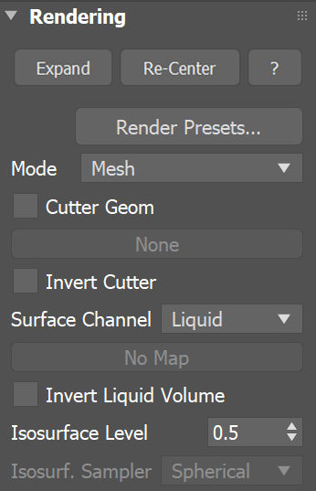
Mode | rendMode – Specifies the method for visualizing the grid content.
...
| |
Since Phoenix is very flexible, it also enables you to render liquid simulations using a volumetric render mode, to create more advanced types of effects. |
| UI Text Box | ||
|---|---|---|
| ||
When rendering as a mesh, Liquid Particles are shaded by a material assigned to the Liquid Simulator object. However, secondary effect particles such as Foam, Splash, Mist and WetMap particles must be shaded using the Phoenix Particle Shader. The Particle Shader can shade a specified Particle System as either Points, Bubbles, Cellular, Splashes, or Fog, depending on the mode you select. |
For even more advanced control over the shading, you can use the Phoenix Grid Texture. It reads from the simulation’s Grid Channels to generate a procedural texture, which can then be used to shade the simulation wherever colors are needed.
It can also be plugged into the texture slots of a material. For example, if you want to mix together liquids with multiple RGB colors emitted from different Liquid Sources, the Grid Texture can be used to read and transfer the RGB colors to the Liquid mesh's material for shading.
Similarly, a Phoenix Particle Texture can be used to read particles and color their positions. When used to read WetMap particles, it can act as a mask to blend between two materials, for example, a wet material and a dry surface material. This way, geometry covered by WetMap particles can appear wet, and the rest of the geometry can appear dry.
| UI Text Box | ||
|---|---|---|
| ||
UI Path: ||Select Liquid Simulator object|| > Modify panel > Rendering rollout |
Actions
...
| UI Text Box | ||
|---|---|---|
| ||
Render settings are not stored within the caches themselves, so if you want to use the same render settings for another simulator or project, there is the option to save and load them as Phoenix Render Presets in the “.tpr” file format. |
Render Presets... – Opens a menu for loading and saving different presets. The following options are available:
| Fancy Bullets | ||
|---|---|---|
| ||
|
Parameters
...
| Section | ||||||||||||||||||||||||||||||||||||||||||||||||||||||||||||||||||
|---|---|---|---|---|---|---|---|---|---|---|---|---|---|---|---|---|---|---|---|---|---|---|---|---|---|---|---|---|---|---|---|---|---|---|---|---|---|---|---|---|---|---|---|---|---|---|---|---|---|---|---|---|---|---|---|---|---|---|---|---|---|---|---|---|---|---|
|
| UI Text Box | ||||||||||||||||||||||||||||||||||
|---|---|---|---|---|---|---|---|---|---|---|---|---|---|---|---|---|---|---|---|---|---|---|---|---|---|---|---|---|---|---|---|---|---|---|
| ||||||||||||||||||||||||||||||||||
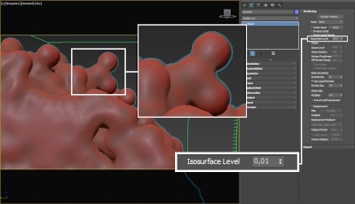
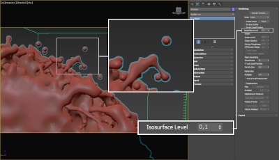
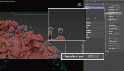
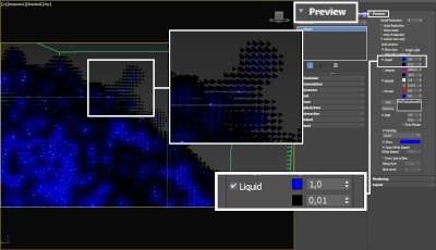
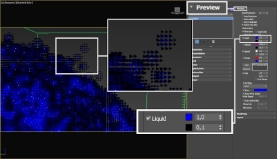
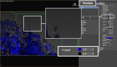
The proper value for the Isosurface Level parameter depends on the numerical range of the surface channel. For example, Phoenix liquids are kept in the range of 0 to 1. A value of 0 means there is no liquid in a certain voxel, and a value of 1 means the cell is 100% full of liquid. Values in between indicate a certain mixture of air and liquid. For such cache files, an Isosurface Level value of 0.5 is best for visualizing the surface between the air and liquid. Imported caches from Houdini, on the other hand, use positive and negative values to indicate whether a voxel is inside or outside the liquid volume, so a correct "halfway" Isosurface Level value would be 0.0. Please check the Grid Channel Ranges page for information about other grid channels.
|
Ocean
...
| Section | |||||||||||||||||||||||||||||||||||
|---|---|---|---|---|---|---|---|---|---|---|---|---|---|---|---|---|---|---|---|---|---|---|---|---|---|---|---|---|---|---|---|---|---|---|---|
|
| Anchor | ||||
|---|---|---|---|---|
|
...
| Section | ||||||||||||||||||||||||||||||||
|---|---|---|---|---|---|---|---|---|---|---|---|---|---|---|---|---|---|---|---|---|---|---|---|---|---|---|---|---|---|---|---|---|
|
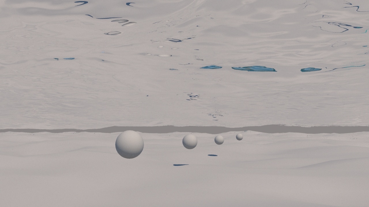
Anchor UnderwaterGoggles UnderwaterGoggles
Example: Underwater Goggles
...
| Section | ||||||||||||||||||||||||||||||||
|---|---|---|---|---|---|---|---|---|---|---|---|---|---|---|---|---|---|---|---|---|---|---|---|---|---|---|---|---|---|---|---|---|
|
Mesh Smoothing
| Anchor | ||||
|---|---|---|---|---|
|
...
| Section | |||||
|---|---|---|---|---|---|
|
...
| UI Text Box | ||||
|---|---|---|---|---|
| ||||
If using a Render Cutter for a liquid pouring into a glass or otherwise contained into another refractive object, you may need to set the Mode to Isosurface. By default, the mode is set to Mesh which may produce artifacts in the rendered image. |
...
Inverse Cutter | invgizmo – When enabled, rendering will occur only outside of the render cutter. This is not the same as a cutter with inverted geometry because any rays that do not intersect the cutter will be shaded as well.
Invert Liquid Volume | solidbelow – By default, grid values above 0.5 are assumed to be liquid, and values below 0.5 are assumed empty. When enabled, the convention switches to the opposite such that values above 0.5 are assumed empty, and values below 0.5 are assumed to be liquid.
Isosurface Level | surflevel - Allows you to specify a treshold value for the generation of the liquid surface. Grid cells below this value will be ignored. By default, the Isosurface Level is set to 0.5 and should only be modified if there is flickering in the generated geometry. Isosurface Level is used only in Isosurface, Mesh, Ocean Mesh and Cap Mesh Modes.
...
| size | medium |
|---|---|
| type | note |
The proper value for the Isosurface Level parameter depends on the numerical range of the surface channel. For example, Phoenix FD liquids are kept in the range of 0 to 1. A value of 0 means there is no liquid in a certain voxel, and a value of 1 means the cell is 100% full of liquid. Values in between indicate a certain mixture of air and liquid. For such cache files, an Isosurface Level value of 0.5 is best for visualizing the surface between the air and liquid. Imported caches from Houdini, on the other hand, use positive and negative values to indicate whether a voxel is inside or outside the liquid volume, so a correct "halfway" Isosurface Level value would be 0.0.
| Section | |||||||||||||||
|---|---|---|---|---|---|---|---|---|---|---|---|---|---|---|---|
|
| Section | |||||||||||||||
|---|---|---|---|---|---|---|---|---|---|---|---|---|---|---|---|
|
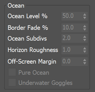
Ocean
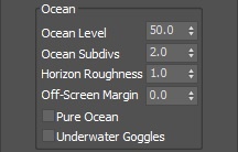
Ocean Level | oceanlevel – Used with the Ocean Mesh and Cap Mesh rendering modes. Specifies the water level as a percentage of the total grid height.
| UI Text Box | ||||
|---|---|---|---|---|
| ||||
|
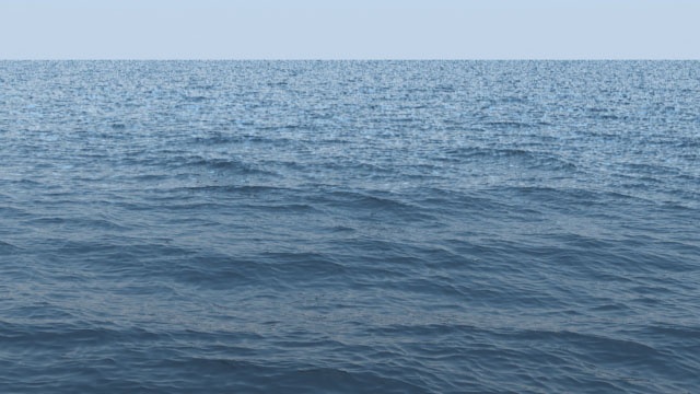
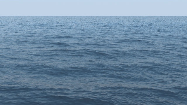
Ocean Subdivs | meshsubdiv – Used with the Ocean Mesh and Cap Mesh rendering modes. When generating the far areas of the surface, this determines how many vertices will be generated for each pixel of the image. Like with V-Ray subdivisions, the square of the parameter value is used. For example, if you increase the subdivisions twice, the vertices count will grow four times. For more information, see the Ocean Subdiv. example below.
| UI Text Box | ||||
|---|---|---|---|---|
| ||||
Increasing the Ocean Subdivs may dramatically increase the amount of consumed RAM. |
Horizon Roughness | oceanhorizrough – Controls the roughness of the distant ocean surface near the horizon. Adds more detail to the waves, which is especially helpful when using a highly reflective material for the ocean surface. Increasing this value can potentially produce visible noise when rendering an animation. To counter this effect, increase the Ocean Subdivs parameter.
Off-Screen Margin (%) | oceanextramargin – The ocean is generated only in the camera view, which can lead to problems when using camera motion blur, using reflections, using refractions with Underwater Goggles enabled, or when the ocean casts shadows on objects underwater. This option allows you to extend the ocean further from the borders of the camera view in order to solve such issues. The value is a percentage of the image size.
Pure Ocean | pureocean – Creates a flat ocean surface up to the Ocean Level height. It does not need loaded caches and if there are any, it ignores their content, so no simulation details will show. Thus changing frames and generating the ocean surface is very quick. This allows you to preview the behavior of the PhoenixOceanTex when Displacement is enabled or if you want to set up your texture for the Wave force. The option is available for both preview and rendering in Ocean Mesh or Cap Mesh modes. During preview, it requires the Show Mesh option to be enabled in the Preview rollout.
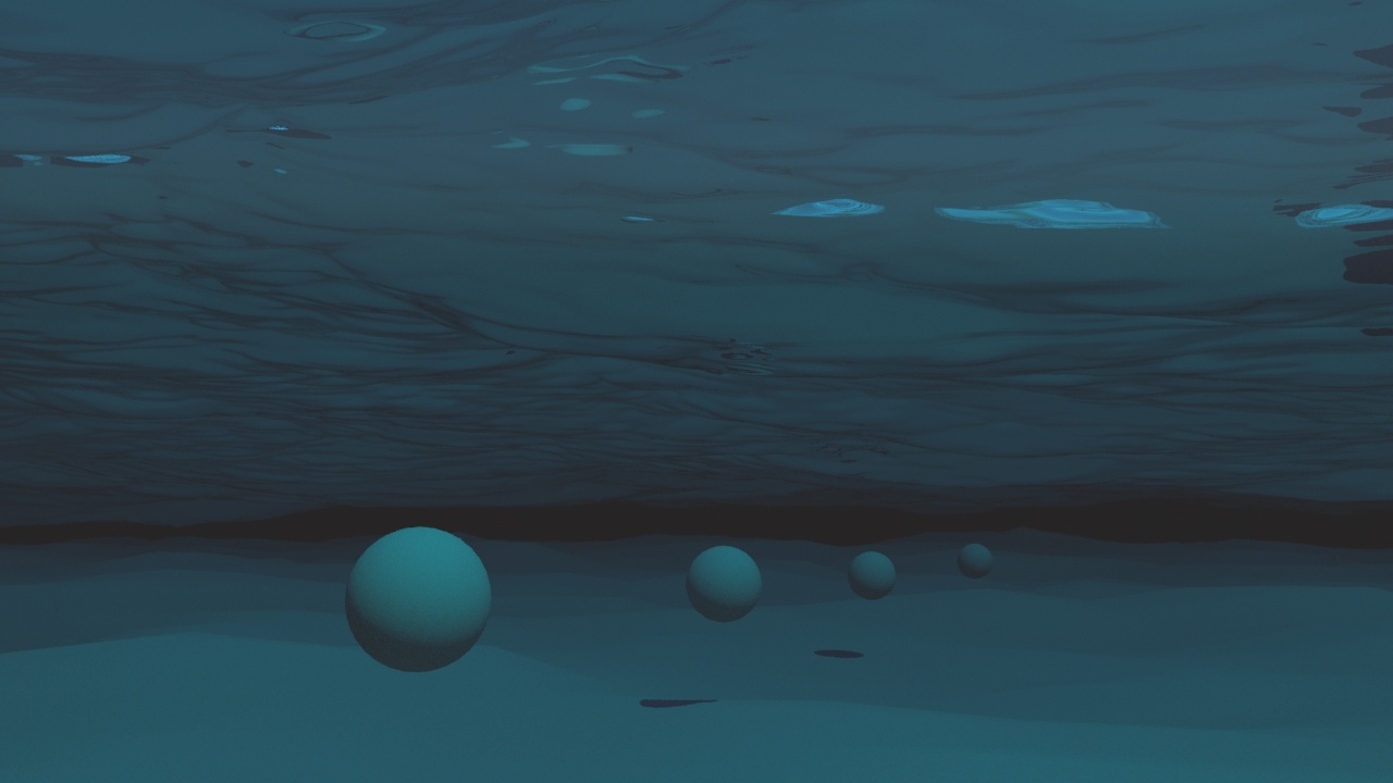
Underwater Goggles | uwglasses – This option is designed to be used when the camera is placed under the water in Ocean Mesh or Cap Mesh mode. When enabled, a few polygons are added in front of the camera, and the grid content is kept outside of the resulting mesh. The result is similar to real underwater goggles in that the field of view shrinks.
...
Example: Ocean Subdivs
| Section | ||||||||||||||||||||
|---|---|---|---|---|---|---|---|---|---|---|---|---|---|---|---|---|---|---|---|---|
|
...
Mesh smooth
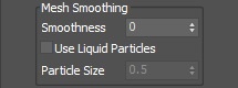
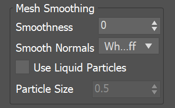
Smoothness | smoothmesh – Specifies the number of smoothing passes. The higher the value, the smoother the result, but the mesh will require more time to calculate.
...
|
...
|
...
|
...
|
...
|
|
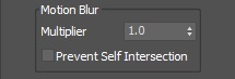
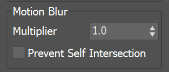
Motion Blur
...
| Section | ||||
|---|---|---|---|---|
|
...
The Motion blur of the mesh is obtained by shifting each vertex along the velocity by the shutter time.
| |||||||||||||
| |||||||||||||
|
...
...
|
...
|
...
|
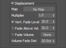
Displacement
...
| Section |
|---|
| UI Text Box | ||||
|---|---|---|---|---|
| ||||
Phoenix meshes are motion blurred in a different way than regular transforming and deforming geometries. When rendering regular meshes with motion blur, the entire mesh is moved along its transformation path back and forward in time, and so each individual vertex of the mesh follows this path. However, for each rendered frame, a new Phoenix mesh must be built from the voxel grid, and so it usually has a different number of vertices than the previous and the next frame. Because of this, individual vertices can not be traced back or forward in time between frames. Instead, motion blur of fluid meshes uses the velocity of vertices which is recorded by the simulation, and moves each vertex back and forward in time along the vertex velocity. This is why the generated liquid mesh does not support frame sub-sampling for motion blur. This may cause a mis-match between the liquid and transforming/deforming objects in your scene that interact with it. The fluid mesh is generated from data at the exact rendered frame and fluid data for the preceding or following frames is not used, unlike regular deforming meshes. As a consequence, the liquid and the objects in your scene would synchronize best if those objects do not use additional geometry samples for motion blur. |
Displacement
| UI Text Box | ||||
|---|---|---|---|---|
| size | medium |
|
|
|
...
|
...
|
...
Multiplier | displmul – Specifies the displacement amount.
...
|
...
|
...
| |||||||
| size | medium
|
|---|
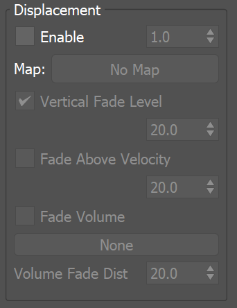
Fade Volume | usefadeobj, fadeobj – When enabled, allows you to specify a geometry object as a fade volume. There will be no displacement inside this object and outside it the displacement will be gradually reduced at a distance specified by the Volume Fadeout Distance parameter.
|
...
|
...
|
...
|
...
|
...
|
...
|
...
|
...
|