![]()
Page History
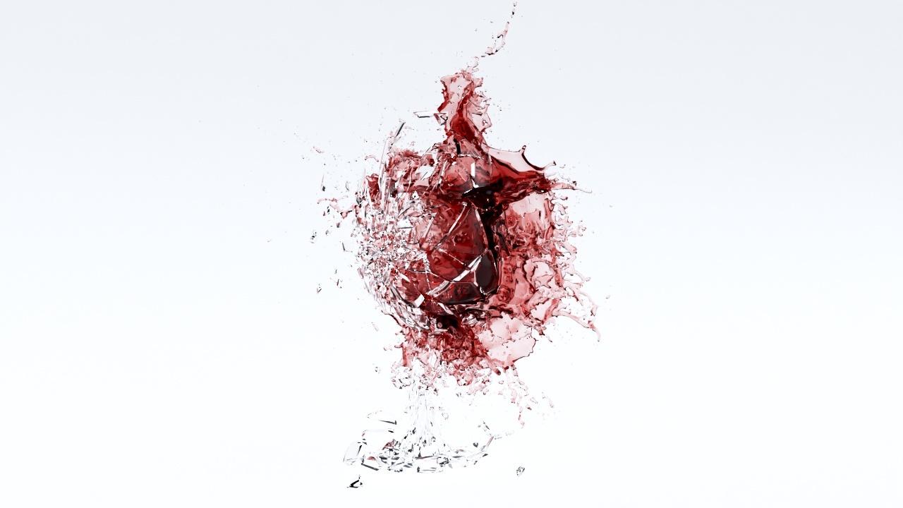
This page provides a tutorial for simulating a liquid for a baked fragmented wine glass using Chaos Phoenix.
Overview
...
| UI Text Box | ||
|---|---|---|
| ||
This is an Entry Level tutorial which requires no previous knowledge of Phoenix. A basic understanding of 3ds Max would be helpful but is not a prerequisite for being able to follow along. |
| Section | ||||||||||||||||||||||
|---|---|---|---|---|---|---|---|---|---|---|---|---|---|---|---|---|---|---|---|---|---|---|
|
Steps
Set Up the System Units
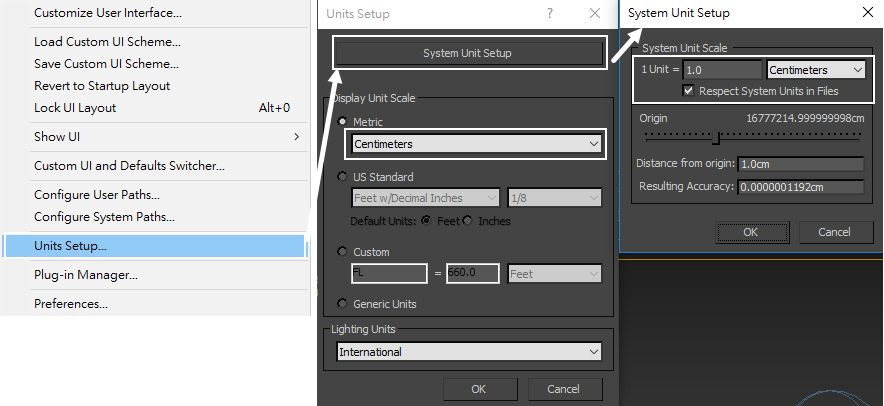
Scene Scale is crucial for the behavior of any simulation. The Phoenix FD solver is not affected by how you choose to view the scene units - what's important is the real-world size in units. Large-scale simulations appear to move more slowly, while a mid-to-small scale simulation has lots of vigorous movement.
Our subject here is a wine glass, so set the Display Unit Scale and System Unit Scale to Centimeters. These options can be found under Customize > Units Setup....
| Section | ||||||||||||||||||||
|---|---|---|---|---|---|---|---|---|---|---|---|---|---|---|---|---|---|---|---|---|
|
In the scene, the glass height has been set to about 267 cm (150 in). The reason for the giant glass is that large scale scenes allow for slower movement. This works well with rigid-body simulations because we can fine-tune movements with greater ease. If the same simulation was conducted at a real-world scale, the glass fragments would travel much faster, making it difficult to capture the exact moment where the glass starts to break.
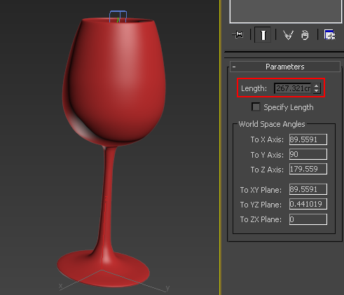
Depending on your scene's needs, you can adjust the glass height as seen here or use the Phoenix FD Scene Scale parameter in the Grid rollout when setting up the simulation.
Set Up the Scene
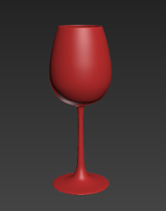
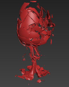
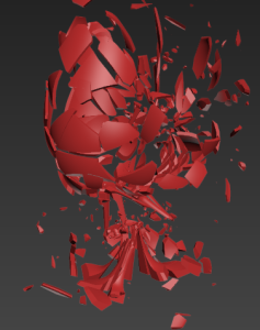
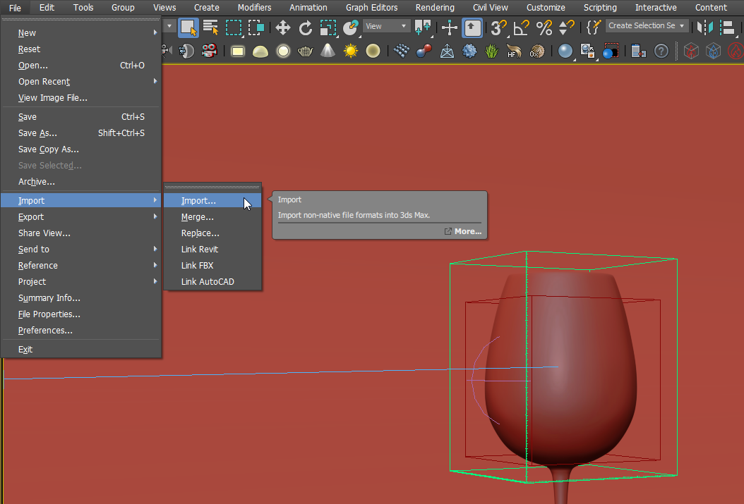
The glass geometry has already been simulated into keyed rigid body fragments. PFlow, Rayfire, or thinkingParticles can be used to create similar effects.
| Section | ||||||||||||||||||||
|---|---|---|---|---|---|---|---|---|---|---|---|---|---|---|---|---|---|---|---|---|
|
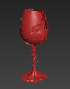
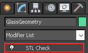
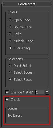
Note the geometry must be a solid (water-tight). You can check it with 3dsMax STL Check modifier. Geometry with a hole or other errors might cause problems when simulating.
| Section | ||||||||||||||||||||
|---|---|---|---|---|---|---|---|---|---|---|---|---|---|---|---|---|---|---|---|---|
|
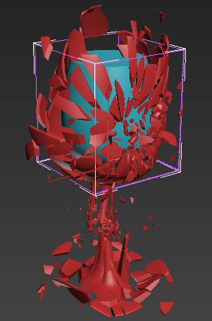
Create a Phoenix FD Liquid Simulator and set grid dimensions so it encompasses the bowl of the glass. We will be using the adaptive grid so the simulator can expand.
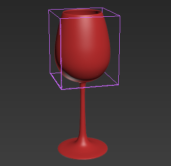
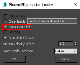
In the image below, the blue geometry in the inside of the glass is used for the initial filled state of the liquid. For more information on creating this, see the Using Initial Liquid Fill with Containers tutorial. Right click to access its Phoenix FD Properties and make sure Initial Liquid Fill is enabled.
|
System Units Setup
...
| Section | ||||||||||
|---|---|---|---|---|---|---|---|---|---|---|
|
Scene Setup
...
| Section | ||||||||||
|---|---|---|---|---|---|---|---|---|---|---|
|
...
| Section | ||||||||||
|---|---|---|---|---|---|---|---|---|---|---|
|
| Section | ||||||||||||||||||||
|---|---|---|---|---|---|---|---|---|---|---|---|---|---|---|---|---|---|---|---|---|
|
...
| UI Text Box | ||
|---|---|---|
| ||
Note that Phoenix works best with closed geometry. You may check it with 3dsMax STL Check modifier. Geometry with a hole or other errors might cause problems when simulating. |
...
| Section | ||||||||||||||||||||
|---|---|---|---|---|---|---|---|---|---|---|---|---|---|---|---|---|---|---|---|---|
|
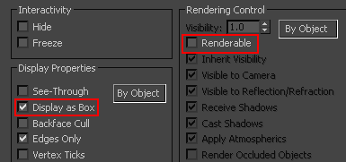
This piece of geometry will not need to be rendered or displayed in the viewport. Access its Object Properties from the quad menu and enable Display as Box and disable Renderable.
Add the Wind Force
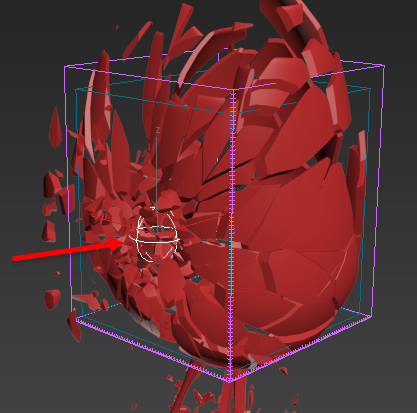
From the Create panel > Space Warps > Forces, create and place a standard 3ds Max Wind force at the center of the glass. Change its type to Spherical. This will cause the force to affect the liquid in all directions. Set the Strength to 4.
| Section | ||||||||||||||||||||
|---|---|---|---|---|---|---|---|---|---|---|---|---|---|---|---|---|---|---|---|---|
|
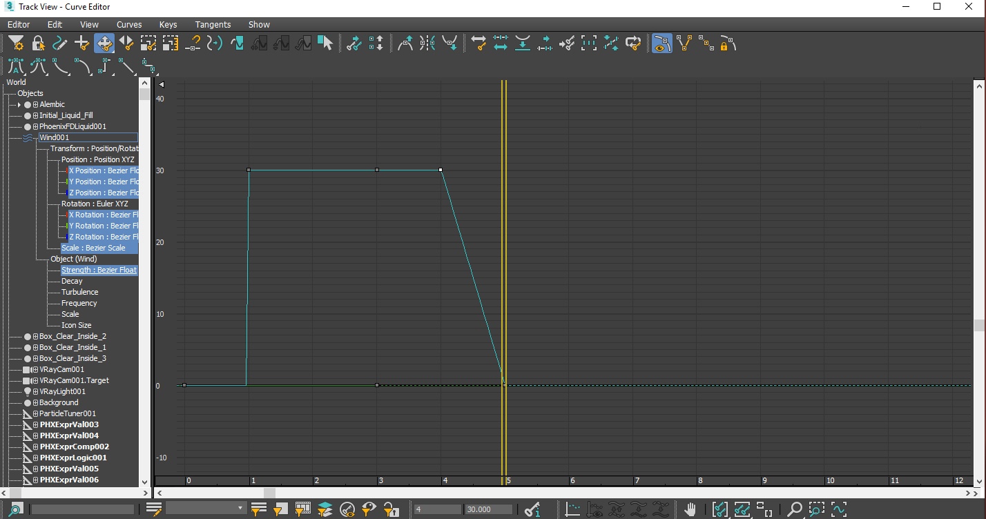
Add a keyframe to the wind Strength to emulate the impact when the glass shatters.
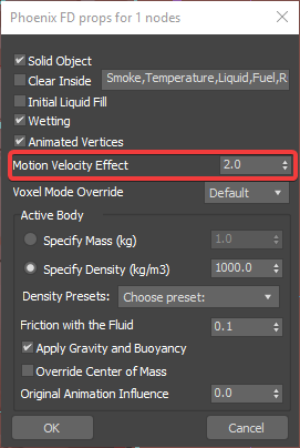
With the help of the Wind force, the RigidBody of the glass will push the liquid to burst and scatter. You can control the interaction strength between the RigidBody and liquid by adjusting the Motion Velocity Effect. This can be accessed by right clicking the glass geometry and opening its Phoenix FD Properties. Higher values will cause the simulation to act as if the liquid is moving at a higher velocity, creating a bigger and more dramatic burst. For this tutorial, we will keep it at its default value of 1.0.
Adjust the Simulation Settings
Simulation requires a lot of hard drive capacity and CPU resources. The physical memory size is the main factor for determining the simulation grid's resolution. As a result, it's important to check how much physical memory is available on the system and determine the grid resolution from there.
The Phoenix Simulator's Simulation rollout provides information on the required RAM. If the machine's RAM is less than the required amount, the hard drive is used for virtual memory. Since hard disk access speeds are slower, the simulation calculation time can become quite long.
To work around this issue, it is best to set the simulation grid to a relatively low resolution while working. Once everything else is ready, you can increase the resolution to production quality. In setting up the simulation, we should pay attention to the required RAM.
Note: Increasing the resolution of liquid sims can change the shape and behavior of the simulation. These side effects are not as apparent with fire/smoke sims. In addition, higher resolution simulations are not necessarily more realistic.
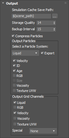
In the Output rollout, enable the Velocity channel in the Output Grid Channels section. This will allow the final mesh to include motion blur.
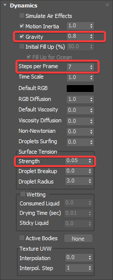
The quality of the liquid’s mesh depends on the Dynamics settings. For this tutorial, we will set the Steps per Frame to 12, Surface tension Strength to 0.05, and enable Wetting.
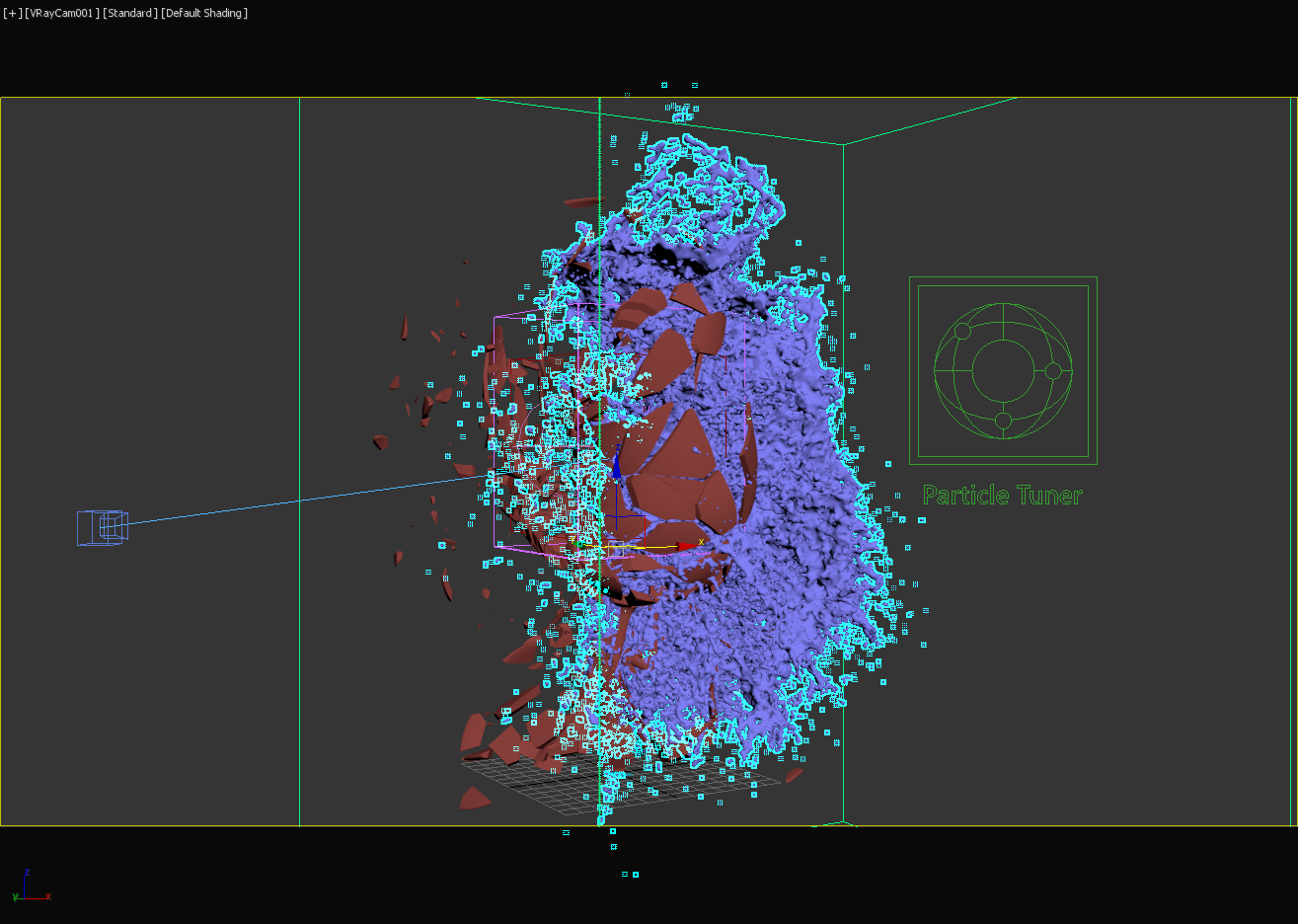
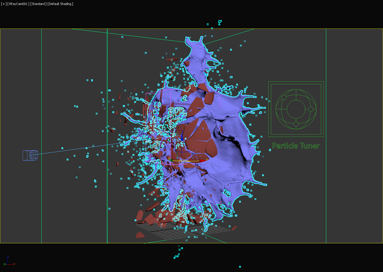
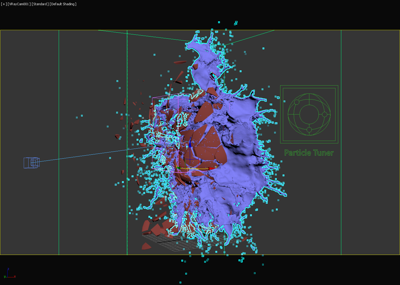
First, let's look at Steps per frame (SPF). SPF controls the iterations of the simulation on each frame. In general, the higher the value, the longer the simulation time, the lower the noise, and the smoother the liquid. Another advantage of a high SPF is that there are fewer chances of a fast-moving liquid penetrating the RigidBody. Note that higher values will not necessarily produce a more realistic liquid mesh.
The following examples show the simulation on frame 3 with different SPF values.
| Section | ||||||||||||||||||||
|---|---|---|---|---|---|---|---|---|---|---|---|---|---|---|---|---|---|---|---|---|
|
Next is the Surface Tension Strength, which controls the elasticity of the liquid surface. Higher values will prevent the liquid from breaking apart into droplets or tendrils. This parameter plays an important role in communicating the scale of small-scale liquid sims.
| Section | |||||||||||||||||||||||||
|---|---|---|---|---|---|---|---|---|---|---|---|---|---|---|---|---|---|---|---|---|---|---|---|---|---|
|
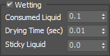
The Wetting option enables wet and dry materials to interact together. This can affect the liquid's behavior depending on the simulation. Note that the wetting simulation produces a particle system called WetMap.
| Section | ||||||||||||||||||||
|---|---|---|---|---|---|---|---|---|---|---|---|---|---|---|---|---|---|---|---|---|
|
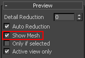
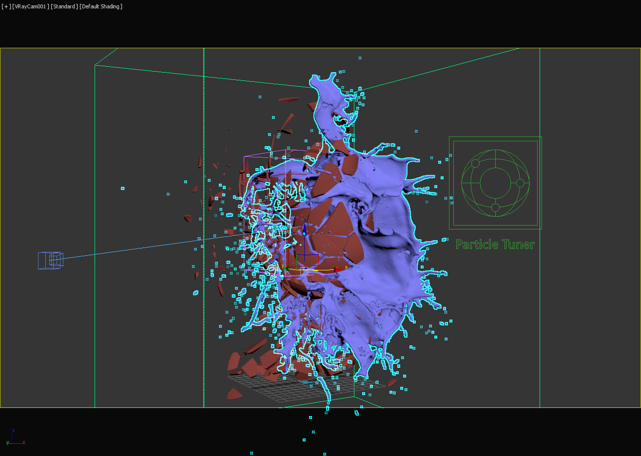
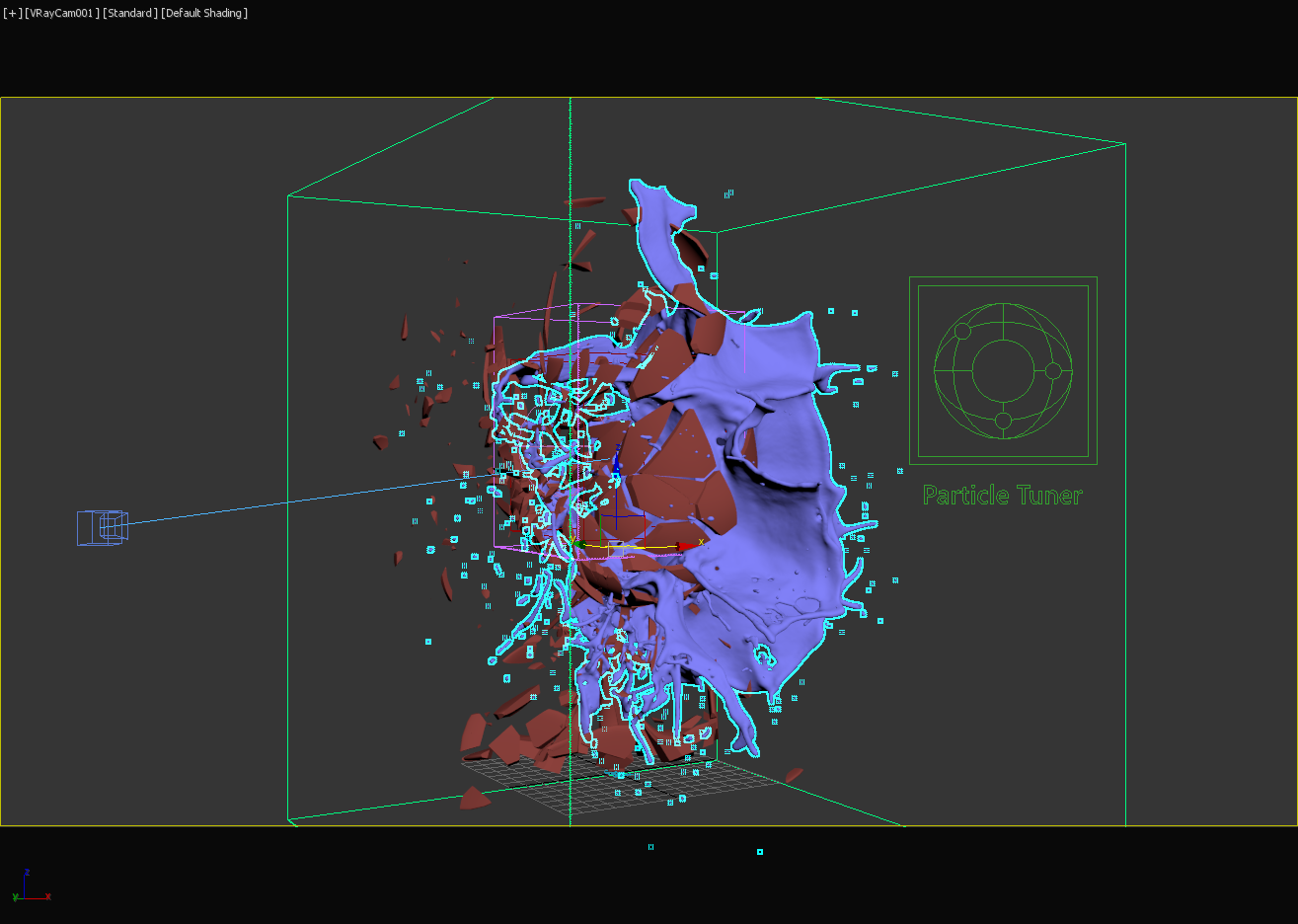
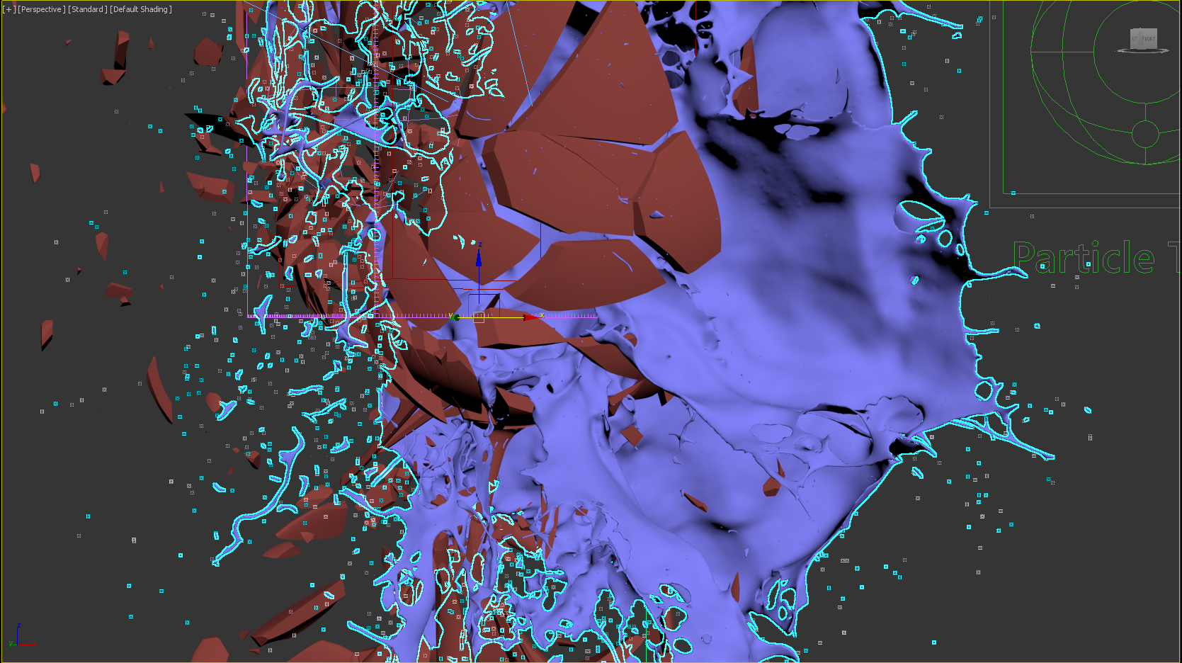
To preview the liquid as a mesh, simply enable the Show Mesh option in the Preview rollout.
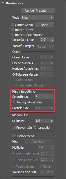
By default, Phoenix FD uses a grid-based method for creating the mesh rather than a particle-based one. As a result, the mesh may appear jagged in places. These artifacts can be reduced by adjusting the Smoothness parameter in the Rendering rollout.
| Section | ||||||||||||||||||||
|---|---|---|---|---|---|---|---|---|---|---|---|---|---|---|---|---|---|---|---|---|
|
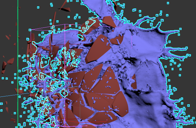
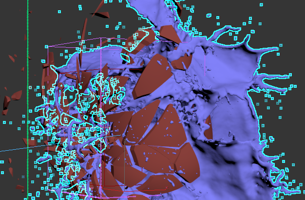
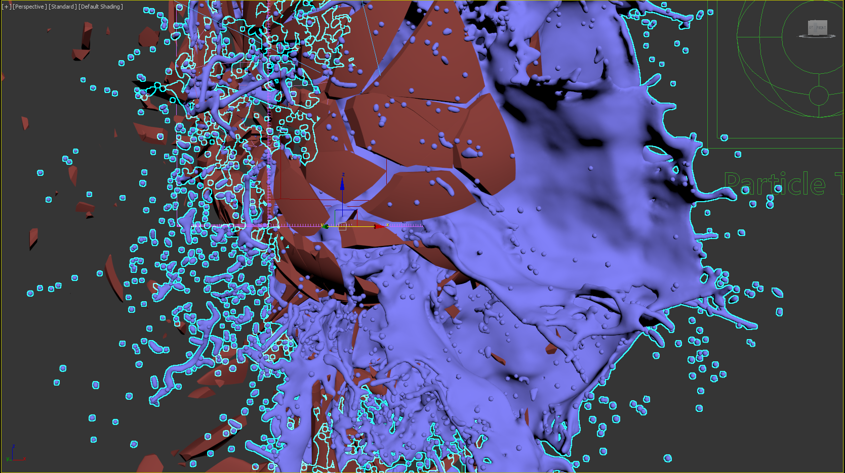
Phoenix also offers a particle-based method for creating the liquid mesh that can be enabled through the Use Liquid Particles option. The resulting mesh will become thinner depending on the specified Particle Size. We will leave Use Liquid Particles disabled for our scene.
Use Liquid Particles enabled
Create the Materials
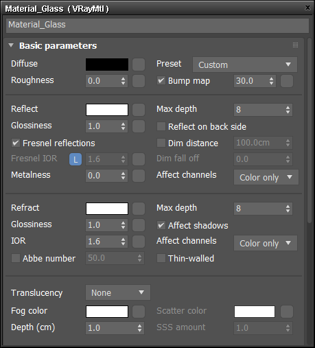
For the materials in the scene, we will start with a standard VRayMtl.
To make a realistic glass material, set the Reflect and Refract colors to white (255, 255, 255). Set the RGlossiness to 0.95, the Fresnel IOR to 1.6, and the Refraction Max depth to 20. In addition, enable Abbe number to add a scattering effect to the glass.
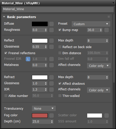
The wine material is a bit more complex. The red wine itself has a special color while also being transparent but not completely translucent. This is where the Fog color comes into play. Have a look at some photos of red wine and sample colors until you get a nice result. Here, we'll be using a Fog color of (166, 23, 20). The Fog multiplier can be used to fine-tune the strength of the fog. Here, we have the multiplier set to 0.005. In addition, the Fog bias allows you to control the color transition. A negative value will make the liquid appear thicker, so set this to -1.0.
For the other red wine material parameters, set the Reflect and Refract colors to white (255, 255, 255). Set RGlossiness to 0.95. Set the Reflect Fresnel IOR to 1.6 and the Refract IOR to 1.3. Note that deliberately setting different values for the Reflect IOR and Refract IOR will produce a more artistic look. Finally, set the Refract Max depth to 20, enable the Abbe number, and set the BRDF type to Phong.
| Section | |||||||||||||||||||||||||
|---|---|---|---|---|---|---|---|---|---|---|---|---|---|---|---|---|---|---|---|---|---|---|---|---|---|
|
Set Up the Lighting and Camera
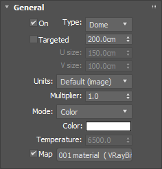
A simple V-Ray Dome Light | VRayLight with a V-Ray Bitmap Texture | VRayHDRI is used to light the scene.
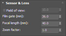
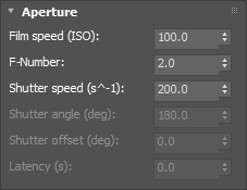
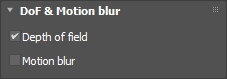
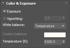
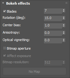
For the camera, we will be using a VRayPhysicalCamera. Since the framing will be a close-up, enable the camera Depth of Field and adjust the f-number. Here, we have it set to 1.2. In the Bokeh effects section, set the blades to 7, the rotation (deg) to 15.0, and the center bias to 1.0. This will add some imperfect details to the lens. In the Sampling section, enable the motion blur option as well.
Forces
...
| Section | ||||||||||||
|---|---|---|---|---|---|---|---|---|---|---|---|---|
|
...
| Section | ||||||||||
|---|---|---|---|---|---|---|---|---|---|---|
|
...
| Section | ||||||||||
|---|---|---|---|---|---|---|---|---|---|---|
|
...
| Section | ||||||||||
|---|---|---|---|---|---|---|---|---|---|---|
|
Container Properties
...
| Section | ||||||||||
|---|---|---|---|---|---|---|---|---|---|---|
|
...
In the image below, the blue geometry in the inside of the glass is used for the initial filled state of the liquid. For more information on creating this, see the Using Initial Liquid Fill with Containers tutorial. Right click to access its Chaos Phoenix Per-Node Properties and make sure Initial Liquid Fill is enabled.
| Section | ||||||||||||||||||||
|---|---|---|---|---|---|---|---|---|---|---|---|---|---|---|---|---|---|---|---|---|
|
...
| Section | ||||||||||
|---|---|---|---|---|---|---|---|---|---|---|
|
...
| Section | ||||||||||
|---|---|---|---|---|---|---|---|---|---|---|
|

| Note |
|---|
Increasing the resolution of the grid can sometimes alter the shape and behavior of the simulation. Remember that higher resolution does not necessarily mean more realistic simulations. It depends on the project. Sometimes the resolution is too high, and there are too many details, or the look is not what the director is asking for. You have to find a good balance. |
...
| Section | ||||||||||
|---|---|---|---|---|---|---|---|---|---|---|
|
...
| Section | ||||||||||
|---|---|---|---|---|---|---|---|---|---|---|
|
...
| Section | |||||||||||||||||||||||||||
|---|---|---|---|---|---|---|---|---|---|---|---|---|---|---|---|---|---|---|---|---|---|---|---|---|---|---|---|
|
...
| Section | |||||||||||||||||||||||||||
|---|---|---|---|---|---|---|---|---|---|---|---|---|---|---|---|---|---|---|---|---|---|---|---|---|---|---|---|
|
...
| Section | ||||||||||
|---|---|---|---|---|---|---|---|---|---|---|
|
...
| Section | ||||||||||
|---|---|---|---|---|---|---|---|---|---|---|
|
...
| Section | ||||||||||||||||||||||
|---|---|---|---|---|---|---|---|---|---|---|---|---|---|---|---|---|---|---|---|---|---|---|
|
...
| Section | ||||||||||||||||||||||
|---|---|---|---|---|---|---|---|---|---|---|---|---|---|---|---|---|---|---|---|---|---|---|
|
...
| Section | ||||||||||
|---|---|---|---|---|---|---|---|---|---|---|
|
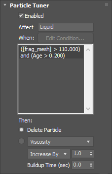
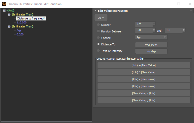
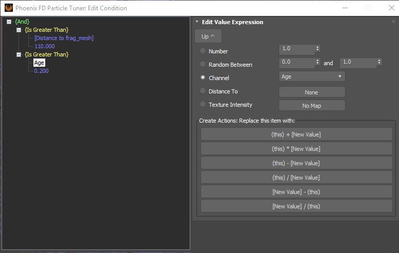
Particle Tuner
...
| Section | ||||||||||||
|---|---|---|---|---|---|---|---|---|---|---|---|---|
|
| Section | ||||||||||
|---|---|---|---|---|---|---|---|---|---|---|
|
| UI Text Box | ||
|---|---|---|
| ||
When using the Age channel as a condition in the Particle Tuner - make sure that the Age checkbox for the affected particle group is enabled in the Output rollout of the simulator. |
| UI Text Box | ||
|---|---|---|
| ||
It is very important to pick the correct mesh for the distance expression. In this case "frag_mesh" mesh should be selected, because this is the existing one in the scene after the 2nd frame of the animation. |
Materials
...
Glass Material
...
| Section | ||||||||||
|---|---|---|---|---|---|---|---|---|---|---|
|
Wine Material
...
| Section | ||||||||||
|---|---|---|---|---|---|---|---|---|---|---|
|
Lighting and Camera
...
| Section | |||||||||||||||
|---|---|---|---|---|---|---|---|---|---|---|---|---|---|---|---|
|
...
| Section | |||||||||||||||
|---|---|---|---|---|---|---|---|---|---|---|---|---|---|---|---|
|
...
| Section | ||||||||||
|---|---|---|---|---|---|---|---|---|---|---|
|
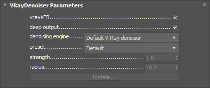
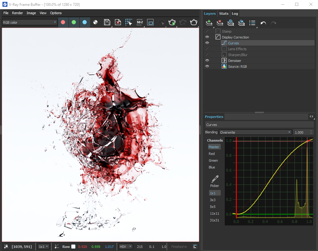
Render Settings
...
| Section | ||||||||||
|---|---|---|---|---|---|---|---|---|---|---|
|
...
| Section | ||||||||||
|---|---|---|---|---|---|---|---|---|---|---|
|
...
| Section | |||||
|---|---|---|---|---|---|
|
...
|
Final Results
...
| Section | ||||||||||
|---|---|---|---|---|---|---|---|---|---|---|
|
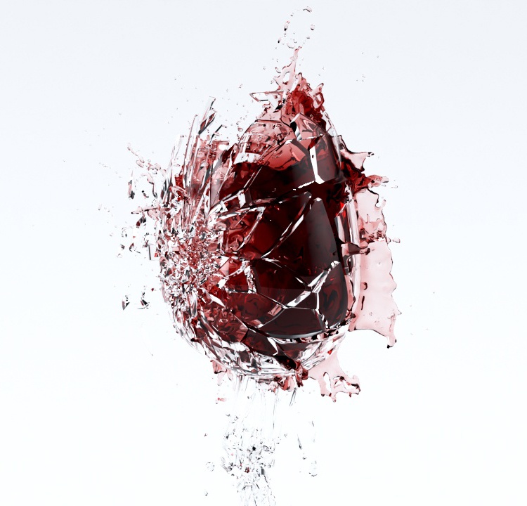
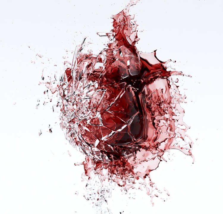
From here, the scene is set up for working on look development, setting up the final composition, and rendering the final image.
...