![]()
Page History
This page provides a step-by-step guide for creating a gasoline explosion simulation using Chaos Phoenix for 3ds Max.
Overview
...
| UI Text Box | ||
|---|---|---|
| ||
This is an Entry Level tutorial which requires no previous knowledge of Phoenix. A basic understanding of 3ds Max would be helpful but is not a prerequisite for being able to follow along. |
| Section | ||||||||||||||||||||||
|---|---|---|---|---|---|---|---|---|---|---|---|---|---|---|---|---|---|---|---|---|---|---|
|
| UI Text Box | ||
|---|---|---|
| ||
|
System Units Setup
...
| Section | ||||||||||
|---|---|---|---|---|---|---|---|---|---|---|
|
Scene Setup
...
In the following steps we will show how to create a gasoline explosion simulation with the Phoenix Gasoline Explosion Preset.
After that we will explain how to set the simulation manually step-by-step for greater flexibility and control.
Gasoline Explosion Preset
...
| Section | ||||||||||
|---|---|---|---|---|---|---|---|---|---|---|
|
...
| Section | ||||||||||
|---|---|---|---|---|---|---|---|---|---|---|
|
...
| Section | ||||||||||
|---|---|---|---|---|---|---|---|---|---|---|
|
...
| Section | ||||||||||
|---|---|---|---|---|---|---|---|---|---|---|
|
...
| Section | ||||||||||
|---|---|---|---|---|---|---|---|---|---|---|
|
...
| Section | ||||||||||
|---|---|---|---|---|---|---|---|---|---|---|
|
Manual Explosion Setup
...
| Section | ||||||||||
|---|---|---|---|---|---|---|---|---|---|---|
|
| Section | |||||||||||||||
|---|---|---|---|---|---|---|---|---|---|---|---|---|---|---|---|
|
| Section | |||||||||||||||
|---|---|---|---|---|---|---|---|---|---|---|---|---|---|---|---|
|
| Section | ||||||||||||||||||||
|---|---|---|---|---|---|---|---|---|---|---|---|---|---|---|---|---|---|---|---|---|
|
| Section | ||||||||||
|---|---|---|---|---|---|---|---|---|---|---|
|
| Section | ||||||||||
|---|---|---|---|---|---|---|---|---|---|---|
|
| Section | ||||||||||
|---|---|---|---|---|---|---|---|---|---|---|
|
| Section | ||||||||||
|---|---|---|---|---|---|---|---|---|---|---|
|
| Section | ||||
|---|---|---|---|---|
|
Page Contents
| Table of Contents | ||
|---|---|---|
|
Introduction
This tutorial covers the basic workflow for creating a gasoline explosion simulation in Phoenix FD for 3ds Max. By the end of it, you will be able to create your own explosion simulation and know the basics of editing some of the main settings of the sim.
To follow this tutorial, you will need to have the Phoenix FD for 3ds Max plugin installed. This tutorial is a companion to go along with the QuickStart video posted on our YouTube channel and available here:
| Align | ||
|---|---|---|
| ||
|
Tutorial Assets
To download the files used in the last part of this tutorial, please click the button below.
| UI Button | ||||||||
|---|---|---|---|---|---|---|---|---|
|
Tutorial Steps
This tutorial shows how to create a gasoline explosion simulation with both the toolbar preset and manual steps for greater flexibility and control.
Units Setup
We will begin by first adjusting the scene units.
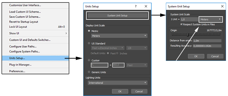
To prepare your scene for rendering an accurate large-scale explosion simulation, make sure you are using appropriate scene units. For this example, we will be using meters. Scene units can be accessed through Customize > Units Setup.
...
| Column | ||
|---|---|---|
| ||
|
| Column | ||
|---|---|---|
| ||
|
...
| width | 40% |
|---|
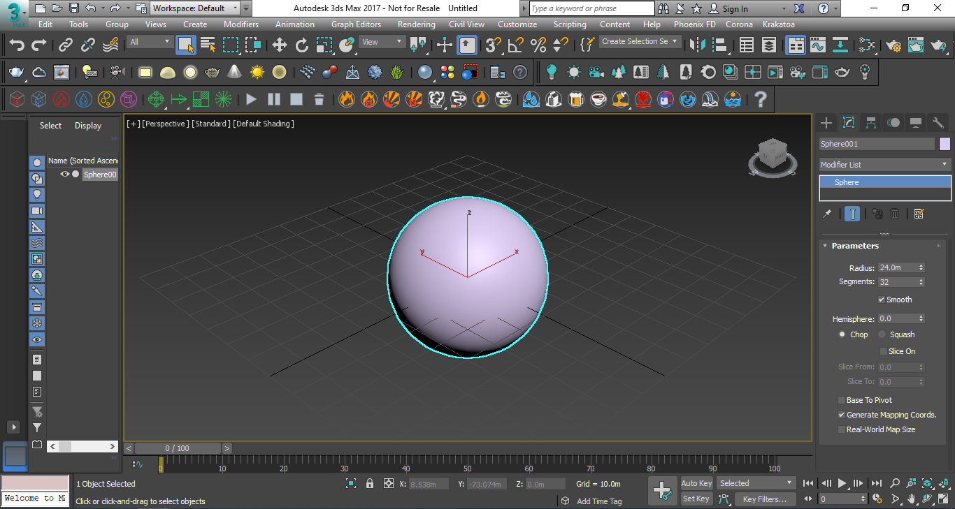
System Units set to 100.0 cm
| Column | ||
|---|---|---|
| ||
|
Create a Sphere with a Radius of 24.0 meters. This sphere will be the source of the explosion.
With the sphere selected, click and hold on the Explosion preset button from the Phoenix FD Toolbar to expand the drop-down menu. Select the second icon, which is the Gasoline Explosion preset.
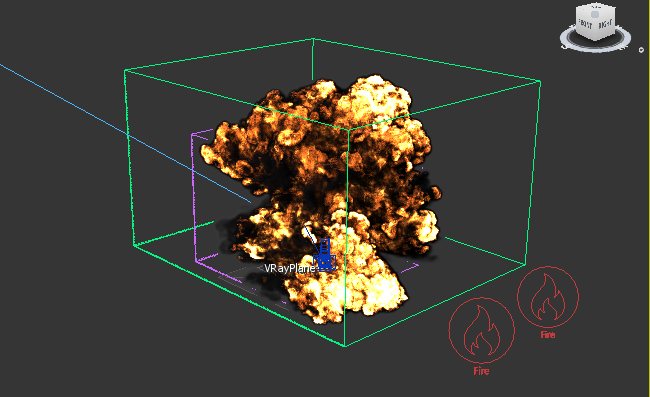
Now click the Start Simulation button in the toolbar.
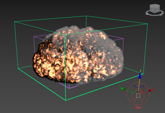
Click Stop Simulation to halt the simulation as it starts to expand beyond the container.
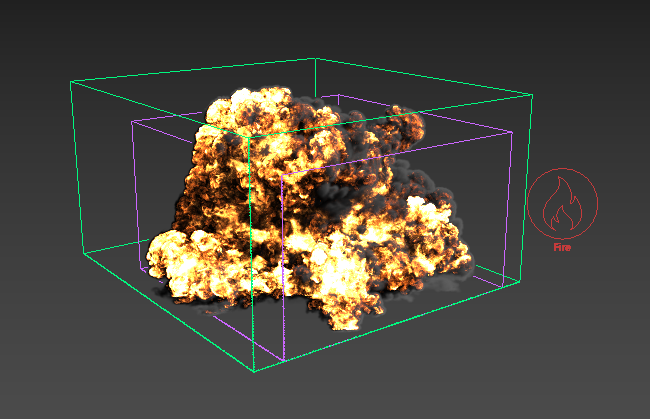
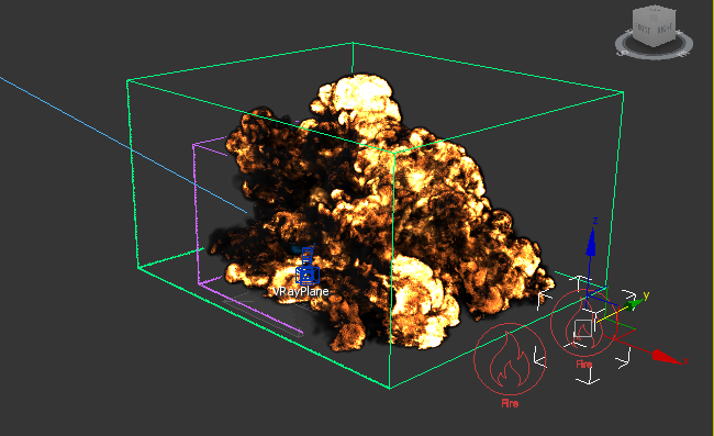
The simulation is complete.
Manual Explosion Setup
Now we did that easily by using the gasoline explosion preset, so let’s take a look at setting this up manually to have more control.
If you are continuing from the preset steps above, select the explosion simulator and source objects and delete them from your scene. Make sure to go to the Phoenix Toolbar and delete the previous simulation cache.
If the sphere has been deleted, create a new Sphere with a Radius of 24.0 meters.
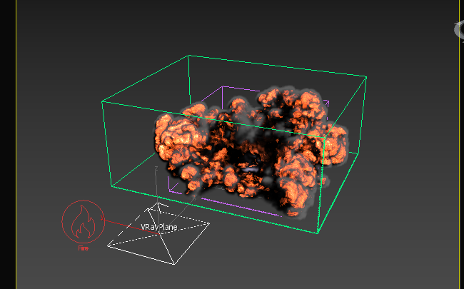
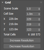
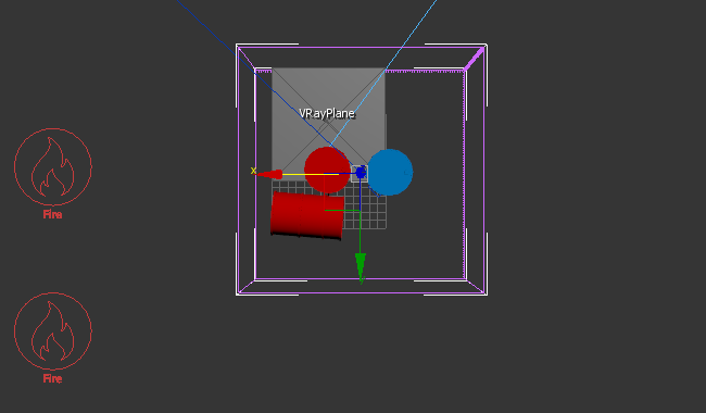
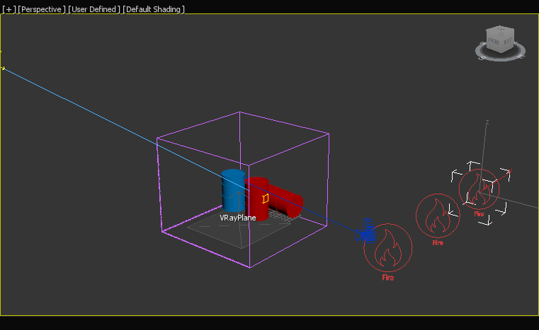
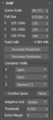
Click on the Create a Fire Simulator button in the toolbar, and click and drag in the viewport to create a volume to encompass the sphere and leave room for the explosion to spread. The volume should be about 229 x 219 x 123m.
...
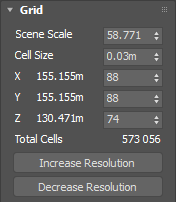
If necessary, adjust the size of the grid volume using the X size, Y size, and Z size parameters in the Grid rollout. Don't scale the grid with 3ds Max scaling tools as this will disrupt the relationship between the Cell size and X/Y/Z size parameters.
Move the sphere near the bottom of the simulator's volume space. Make sure the sphere is still inside the volume.
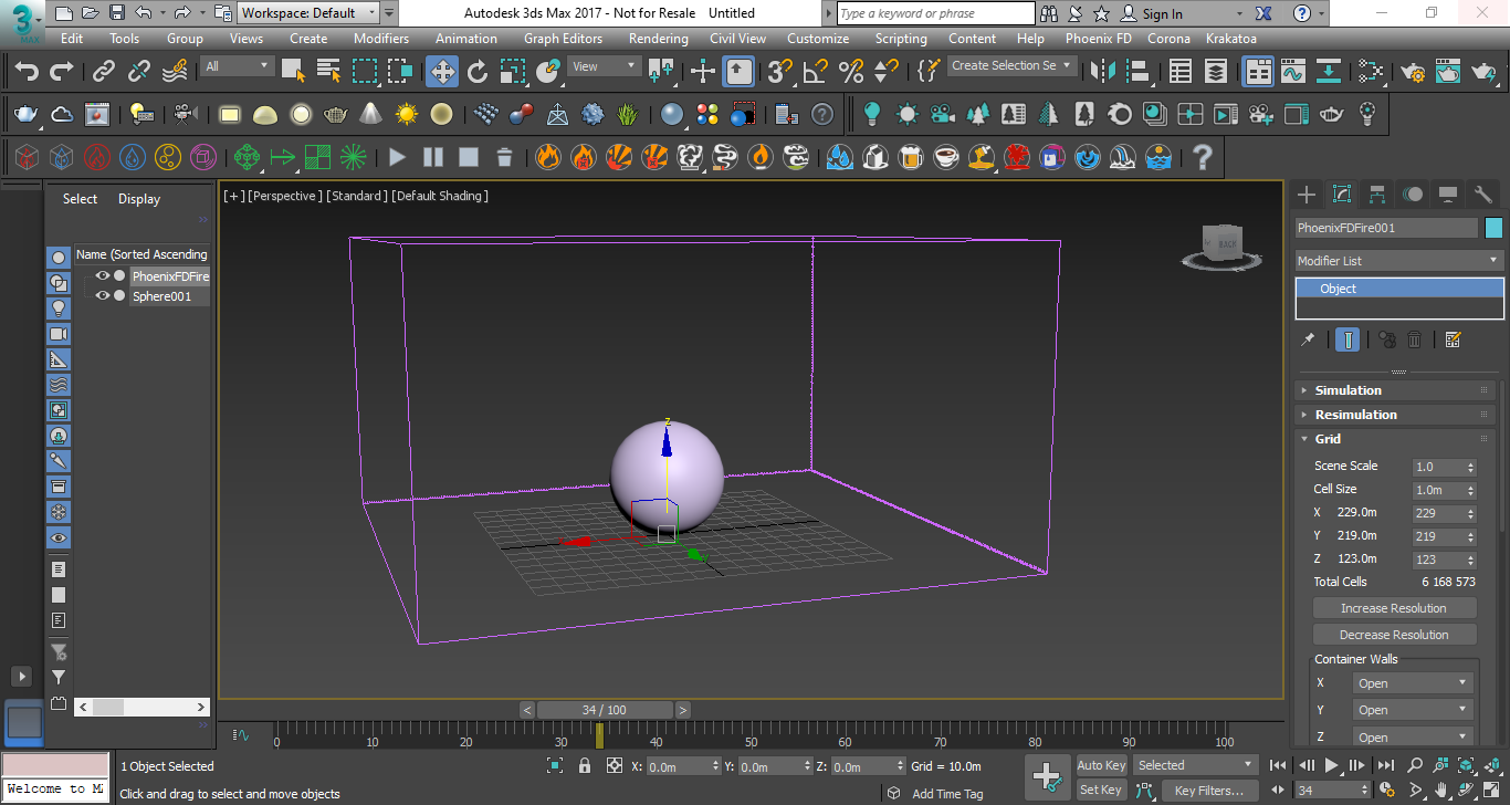
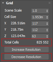
Look in the Grid section of the Simulation properties. Currently, there are about 6 million total cells. To save on simulation time during the iteration process, click Decrease resolution several times until the total cells are around 825,000. For more information regarding simulation resolution, please refer to the Basic Liquids QuickStart page page.
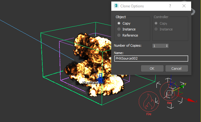
Click the Create a Fire Source button on the toolbar and place the source anywhere in your scene.
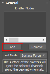
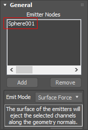
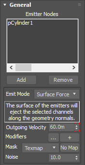
In the Command Panel for the Liquid Source object, click the Add button and select the sphere. This will add the sphere to the Emitter Nodes list, enabling the sphere to be the emitter of the liquid.
| Section | ||||||||||||||||||||
|---|---|---|---|---|---|---|---|---|---|---|---|---|---|---|---|---|---|---|---|---|
|
...
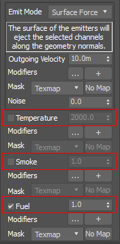
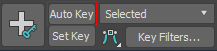
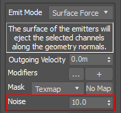
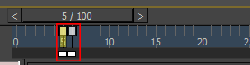
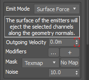
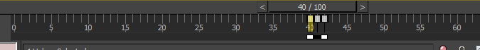
Since we are creating an explosion that will use a large amount of fuel very quickly, we will need to increase the Outgoing Velocity. The higher this number, the more fluid will be generated per second. In order to create the short but powerful burst of fluid, we will animate the Outgoing Velocity number. Make sure you're at Frame 0, turn on Auto Key, and change the Outgoing Velocity value to 2000.
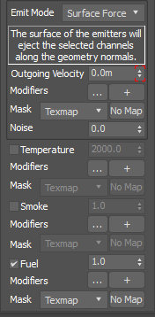
Move to Frame 1 and change the Outgoing Velocity to 0.0, then turn off Auto Key.
...
|
...
|
...
|
...
|
...
|
...
|
...
|
| Section | |||||
|---|---|---|---|---|---|
|
...
|
...
|
...
|
...
|
...
|
...
|
...
|
...
|
| Section | |||||
|---|---|---|---|---|---|
|
...
|
...
...
| Column | ||
|---|---|---|
| ||
|
...
| width | 45% |
|---|
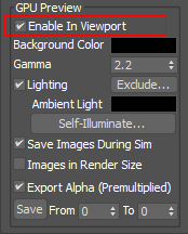
GPU Preview disabled
...
|
...
|
...
|
...
...
| Section | |||
|---|---|---|---|
|
...
|
...
|
...
|
...
|
...
|
...
|
...
|
...
|
...
|
...
|
| Section | |||||
|---|---|---|---|---|---|
|
...
|
...
|
...
|
...
|
...
|
| Section | |||||
|---|---|---|---|---|---|
|
...
|
...
|
| Section | |||||
|---|---|---|---|---|---|
|
...
|
...
|
...
|
...
|
...
|
...
|
...
|
...
| Section | |||||
|---|---|---|---|---|---|
|
...
|
...
|
...
|
.
...
| Section |
|---|
...
|
...
|
...
|
...
|
...
|
...
|
...
|
...
|
...
|
...
|
...
|
...
|
...
|
...
| Section | |||||
|---|---|---|---|---|---|
|
...
|
...
|
.
...
| Section |
|---|
...
|
...
|
...
|
...
|
...
|
...
|
...
|
...
|
...
|
...
The
| Section | |||||
|---|---|---|---|---|---|
|
...
|
...
|
...
|
...
|
...
|
...
|
...
| Section | |||||
|---|---|---|---|---|---|
|
...
|
...
|
...
|
...
| Section | |||||
|---|---|---|---|---|---|
|
...
|
...
|
...
|
...
|
...
|
...
|
...
|
...
|
...
|
...
| Section | |||||
|---|---|---|---|---|---|
|
...
|
...
|
...
|
...
|
...
|
...
|
...
...
| Section | |||||
|---|---|---|---|---|---|
|
...
|
...
|
...
|
...
|
...
|
...
|
...
|
...
|
...
|
...
|
...
|
...
|
...
|
...
| Section | |||||
|---|---|---|---|---|---|
|
...
|
...
|
...
|
...
|
...
|
...
|
...
|
...
| Section | |||||
|---|---|---|---|---|---|
|
...
|
...
| Section | |||||||||||||||
|---|---|---|---|---|---|---|---|---|---|---|---|---|---|---|---|
|
...
| Section | |||||
|---|---|---|---|---|---|
|
...
|
...
|
...
|
...
|
...
|
...
| Section | |||||
|---|---|---|---|---|---|
|
...
|
...
|
...
|
...
|
...
|
...
|
...
|
...
| ||
|
...
| 5% | ||||||||||
| Section | ||||||||||
|---|---|---|---|---|---|---|---|---|---|---|
|
...
| Section | |||||
|---|---|---|---|---|---|
|
...
|
...
|
...
|
...
|
...
|
...
|
...
|
...
|
...
|
...
|
...
|
...
| Section | |||||
|---|---|---|---|---|---|
|
...
|
...
|
...
|
...
|
...
|
|
Rendering
...
| Section | ||||||
|---|---|---|---|---|---|---|
| ||||||
|
...
...
...
| Section | |||||||||||
|---|---|---|---|---|---|---|---|---|---|---|---|
|
...
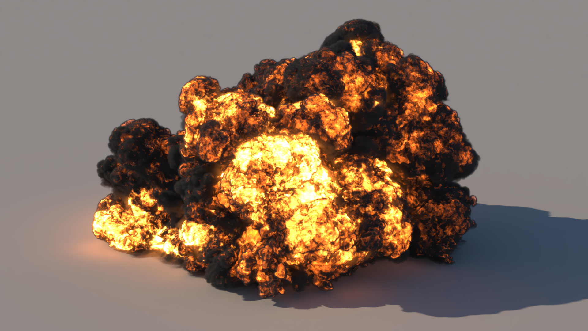
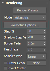
Rendering
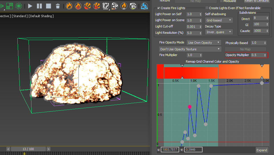
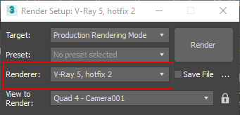
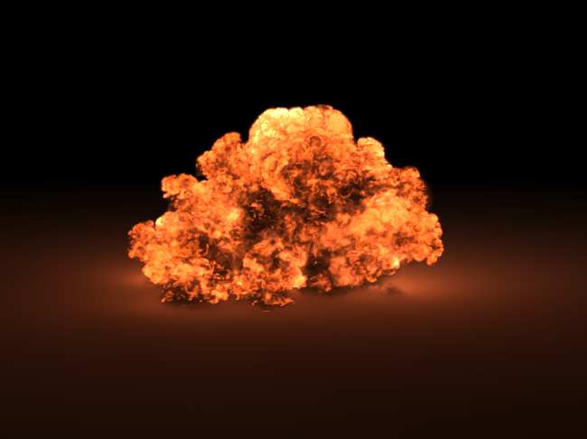
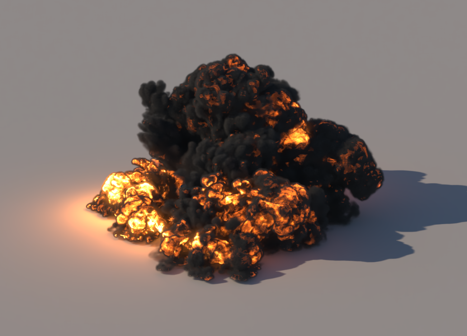
Make sure V-Ray is set to the current renderer in Render Setup. Render the result.
...
| Section | |||||
|---|---|---|---|---|---|
|
...
|
...
|
...
|
...
| |||||
|
...
| Section | |||||||||||
|---|---|---|---|---|---|---|---|---|---|---|---|
|
...
| Section | |||||
|---|---|---|---|---|---|
|
|
...
|
...
|
...
|
...
|
...
|
...
|
...
| |||||
|
...
| Section | |||||||||||
|---|---|---|---|---|---|---|---|---|---|---|---|
|
...
| Section | ||||||
|---|---|---|---|---|---|---|
|
|
...
|
...
|
...
|
...
|
...
|
...
|
...
| Section |
|---|
...
|
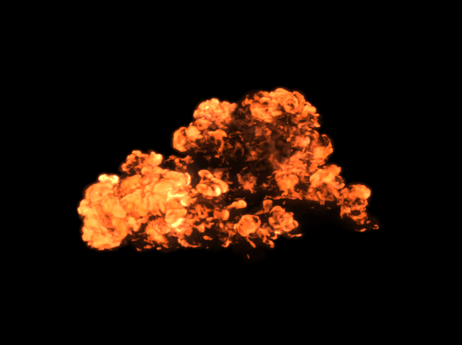
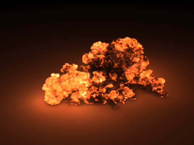
Final render.
Applying the Sim Setup to a Real-World Example
...
|
Example Scene
...
| Section | |||||
|---|---|---|---|---|---|
|
...
|
...
| Section | ||||
|---|---|---|---|---|
|
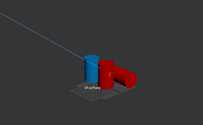
To do this part of the tutorial, download the tutorial file as instructed at the start of this page.
...
|
...
|
...
|
...
|
...
| Section | |||||
|---|---|---|---|---|---|
|
...
|
...
|
...
|
...
|
...
|
...
...
| Section | |||||
|---|---|---|---|---|---|
|
...
|
...
|
...
|
...
| Section | |||||
|---|---|---|---|---|---|
|
...
|
...
|
...
|
...
|
...
| Section | |||||
|---|---|---|---|---|---|
|
...
|
...
...
| Section | |||||
|---|---|---|---|---|---|
|
...
|
...
|
...
|
...
|
...
| Section | |||||
|---|---|---|---|---|---|
|
...
|
...
|
...
|
...
|
...
|
...
|
...
|
...
|
...
| Section | ||||||||
|---|---|---|---|---|---|---|---|---|
|
...
|
...
|
...
| Section | |||||
|---|---|---|---|---|---|
|
...
|
...
|
...
|
...
| Section | |
|---|---|
|
...
|
...
|
...
|
...
|
...
|
...
| Section | ||||||||||
|---|---|---|---|---|---|---|---|---|---|---|
|
...
...
| Section | |||||
|---|---|---|---|---|---|
|
...
|
...
...
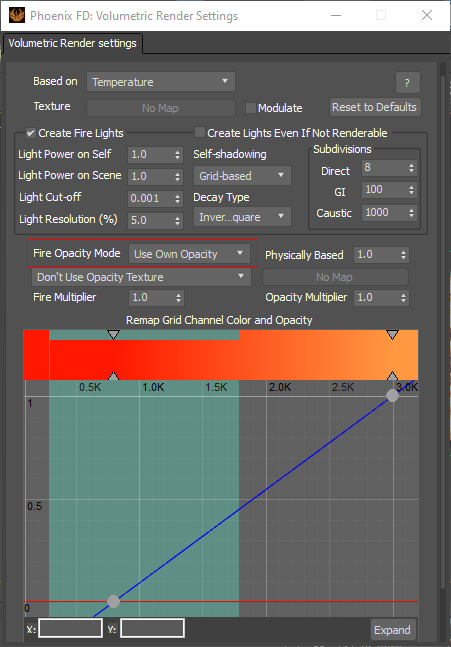
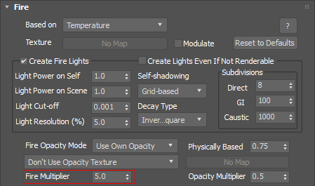
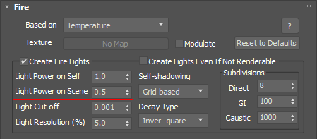
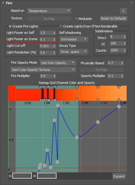
Do a test render to see the results. If the fire is too bright, go into the Volumetric Options and decrease the Fire Multiplier value.
| Section | ||||||||||
|---|---|---|---|---|---|---|---|---|---|---|
|
...
| Section | ||||
|---|---|---|---|---|
|
...
|
...
|
...
|
...
|
...
|
...
|
...
|
...
|
...
|
...
Restart the
| Section | |||||
|---|---|---|---|---|---|
|
...
|
...
|
...
|