![]()
Page History
This page provides a step-by-step guide for creating a simple liquid simulation using Chaos Phoenix for 3ds Max.
Overview
...
| UI Text Box | ||
|---|---|---|
| ||
This is an Entry Level tutorial which requires no previous knowledge of Phoenix. A basic understanding of 3ds Max would be helpful but is not a prerequisite for being able to follow along. |
| Section | |||||
|---|---|---|---|---|---|
|
Page Contents
| Table of Contents | ||
|---|---|---|
|
Introduction
...
|
...
|
...
|
...
|
...
|
...
|
| Align | ||||||||
|---|---|---|---|---|---|---|---|---|
| align | center
|
Tutorial Assets
To download the files used in this tutorial, please click the button below.
| UI Button | ||||||||
|---|---|---|---|---|---|---|---|---|
|
Tutorial Steps
This tutorial shows how to create a basic liquids simulation with both the toolbar preset and manually step-by-step for greater flexibility and control.
Tap Water Preset
...
| UI Text Box | ||
|---|---|---|
| ||
The video is created using Phoenix 3.0, but the text version of the tutorial is updated and uses Phoenix 4.30 Official. In any case of doubt you may refer to the text. |
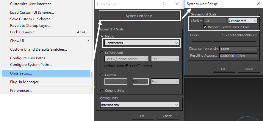
System Units Setup
...
| Section | ||||||||||
|---|---|---|---|---|---|---|---|---|---|---|
|
| UI Text Box | ||
|---|---|---|
| ||
The units do not have to be set to centimeters to get the simulation to work. What's important is that the emitter (in this case, the sphere) is set to the proper real-world scale so that the simulation is correct for that situation. This is how Phoenix is able to know if it's simulating water in a glass or a boat on ocean waves. |
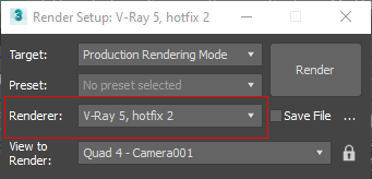
Lightning and Rendering
...
| Section | |||||
|---|---|---|---|---|---|
|
...
|
window.
...
| Section | |||||||||||
|---|---|---|---|---|---|---|---|---|---|---|---|
|
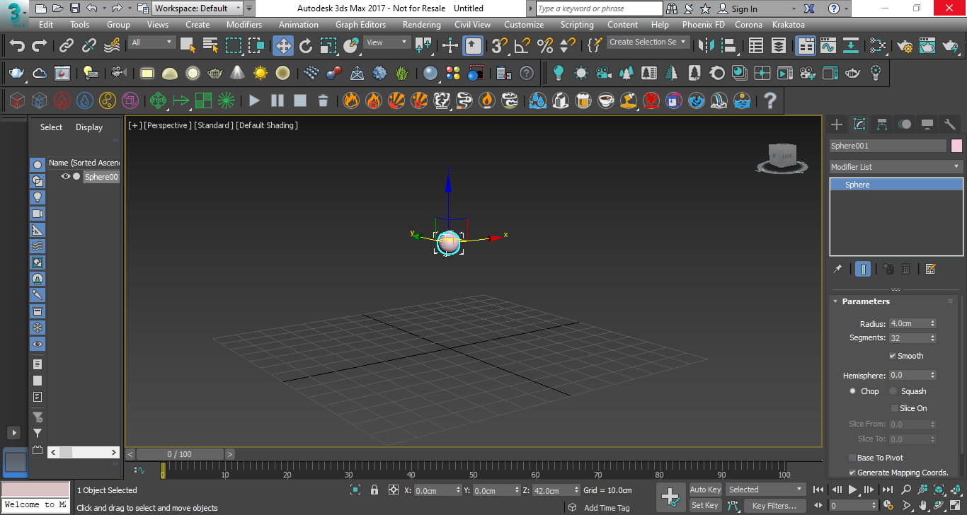
Scene Setup
...
In the following steps we will show how to create a basic liquid simulation with the Phoenix Tap Water Preset.
After that we will explain how to set the simulation manually step-by-step for greater flexibility and control.
Tap Water Preset
...
| Section | ||||||
|---|---|---|---|---|---|---|
| Column | ||||||
| ||||||
|
...
|
...
|
...
|
...
| Section | |||||
|---|---|---|---|---|---|
|
...
|
...
|
...
|
...
| Section | |||||
|---|---|---|---|---|---|
|
...
|
...
|
...
|
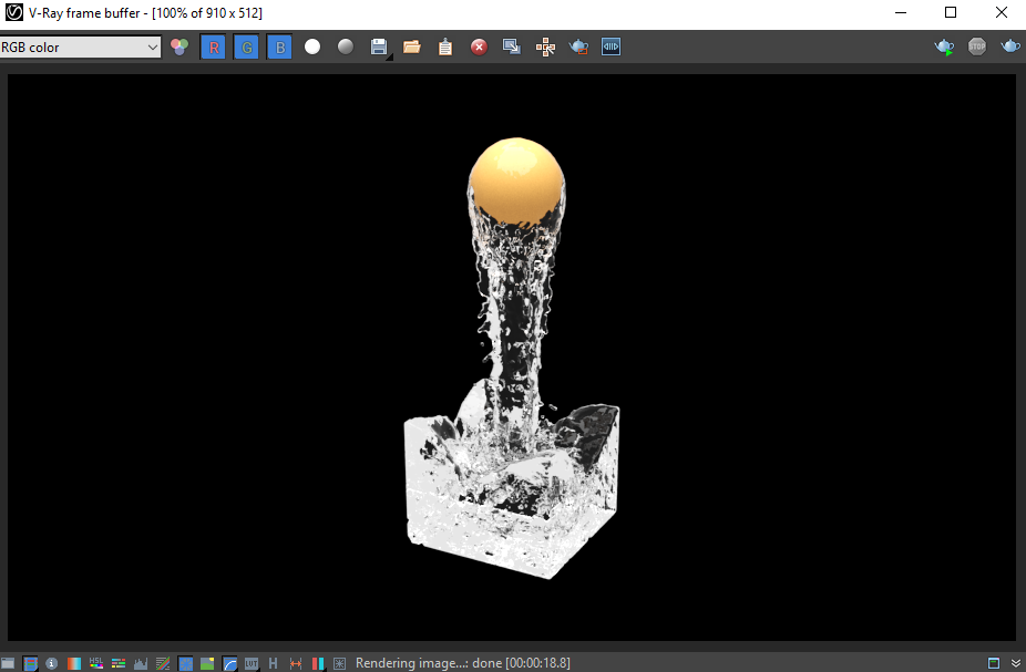
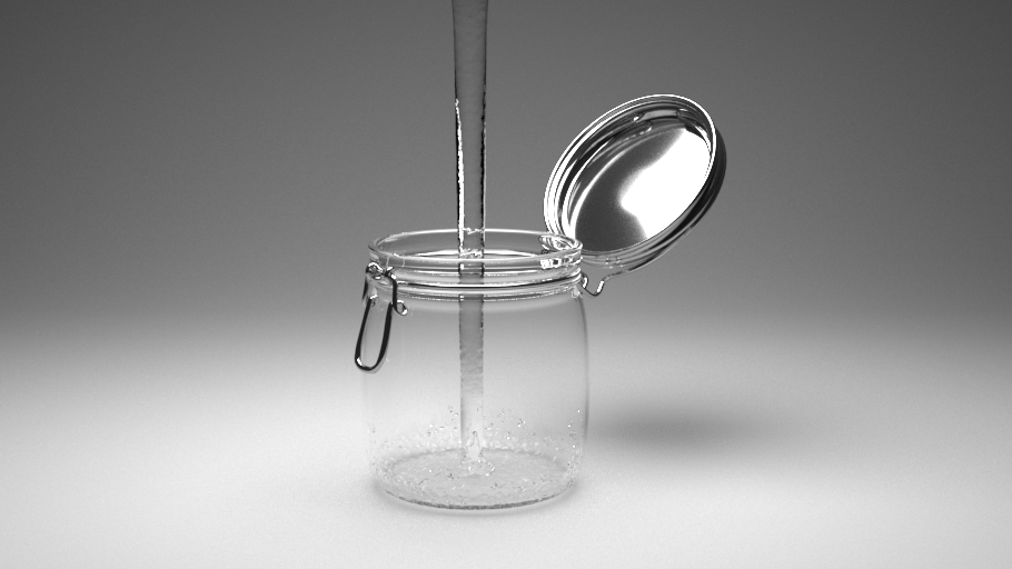
![]()
Click Stop Simulation to halt the simulation as it starts to fill the container.
![]()
|
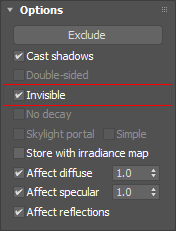
Add a Dome light to your scene and set it to be Invisible to make it easier to focus on the simulation.
...
| Section | |||||||||||
|---|---|---|---|---|---|---|---|---|---|---|---|
|
...
| Section | |||||||||
|---|---|---|---|---|---|---|---|---|---|
|
...
|
...
|
...
|
...
Manual Water Setup
...
| Section | |||||
|---|---|---|---|---|---|
|
...
|
...
|
...
|
...
|
...
|
...
|
...
|
...
|
...
|
...
|
...
...
|
...
|
...
|
| Section | |||||
|---|---|---|---|---|---|
|
...
|
...
|
...
|
...
|
...
| Section | |
|---|---|
|
...
|
...
|
...
|
...
|
...
|
...
|
...
| width | 40% |
|---|
| Section |
|---|
...
|
...
...
|
...
|
...
|
...
|
...
|
...
|
...
|
...
|
...
|
...
|
...
|
...
|

| Section | |||||
|---|---|---|---|---|---|
|
...
|
...
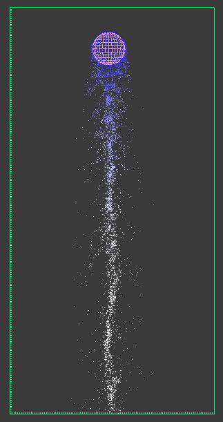
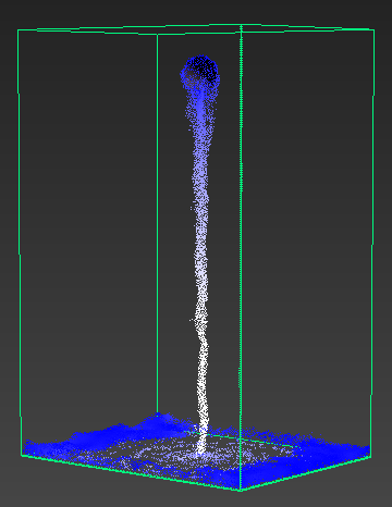
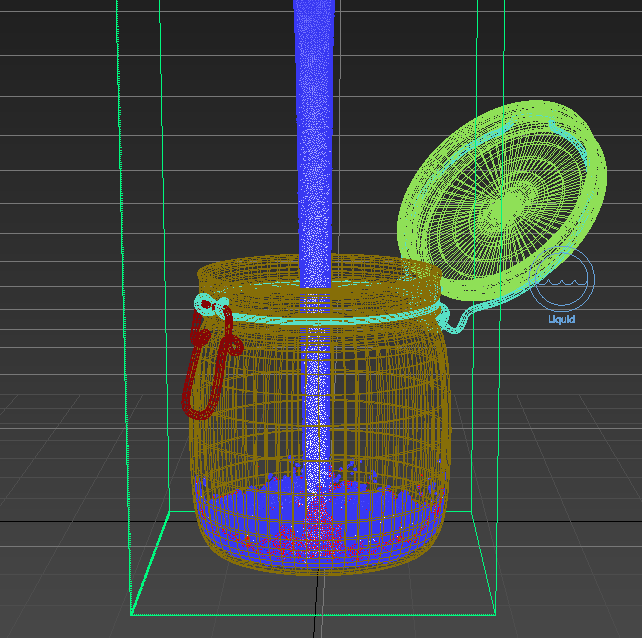
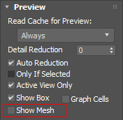
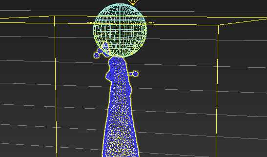
The simulation is currently all white. We can cause the particles to change color depending on their speed of travel. Select the Simulator and expand the Preview rollout. We will offset the White speed parameter by making it higher, introducing blue into the simulation where the particles are not traveling as fast as this value. Set White speed to a higher value such as 800 or 1200. The particles start off as blue (the default color next to the Show option) and become white after a few frames.
| Section | |||||
|---|---|---|---|---|---|
|
...
|
...
|
...
|
...
|
...
|
...
...
|
...
...
| width | 40% |
|---|
|
...
...
| Section |
|---|
...
|
...
...
|
...
|
...
|
...
|
...
|
...
|
...
|
...
|
...
|
...
|
| Section | |||||
|---|---|---|---|---|---|
|
...
|
...
|
...
|
...
|
...
|
...
|
...
|
...
|
...
|
...
|
...
|
...
|
...
|
...
|
...
|
...
|
| Section | |||||
|---|---|---|---|---|---|
|
...
|
...
|
...
|
...
|
...
|
| Section | ||||
|---|---|---|---|---|
|
|
...
|
![]()
|
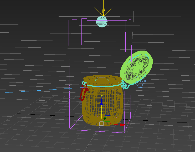
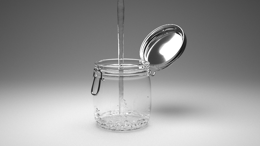
Applying the Sim Setup to a Real-world Example
Example Scene
...
| Section | |||||
|---|---|---|---|---|---|
|
...
|
...
|
...
|
...
|
...
...
| Section | ||||||||||
|---|---|---|---|---|---|---|---|---|---|---|
|
...
| Section | |
|---|---|
|
...
|
...
|
...
|
...
|
...
|
...
|
...
|
...
|
...
|
...
|
...
|
...
|
...
|
...
| Section | |||||
|---|---|---|---|---|---|
|
...
|
...
|
...
|
...
| Section | |||||
|---|---|---|---|---|---|
|
...
|
...
|
...
|

...
| Section | |||||
|---|---|---|---|---|---|
|
...
|
...
| |||||
|
...
| Section | ||||||||||||
|---|---|---|---|---|---|---|---|---|---|---|---|---|
|
...
| Section | |||||
|---|---|---|---|---|---|
|
|
...
|
...
|
...
| Section | |||||
|---|---|---|---|---|---|
|
...
|
...
|
...
|
...
|
...
|
...
|
...
|
...
|
...
|
...
|
...
| Section | |||||
|---|---|---|---|---|---|
|
...
|
...
|
...
|
...
|
...
|
...
|
...
|

...
Set the
| Section | |||||
|---|---|---|---|---|---|
|
...
|
...
|
...
|
...
|
...
|
...
| Section | |||||
|---|---|---|---|---|---|
|
...
|
...
|
...
|
...
|
...
|
...
|
...
|
...
|
...
|
...
|
...
|
...
| Section |
|---|
...
|
...
|
...
|
...
|
...
| Section | |||||
|---|---|---|---|---|---|
|
...
|
...
|
...
|
...
|
...
|
...
|
...
|
...
| Section | |||||
|---|---|---|---|---|---|
|
...
|
...
|
...
| Section | |||||
|---|---|---|---|---|---|
|
...
|
...
|
...
| Section | |||||
|---|---|---|---|---|---|
|
...
|
...
|
...