![]()
Page History
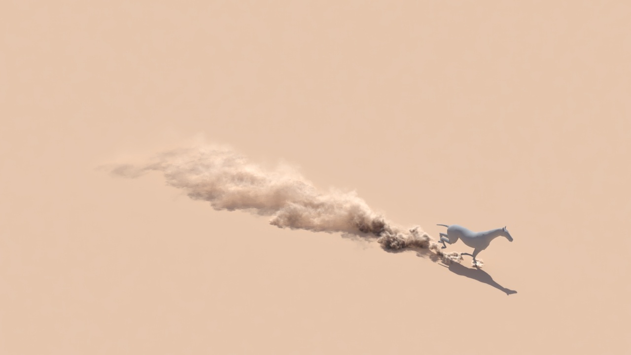
This page provides a tutorial on creating a Procedural Ground Dust simulation with Voxel Tuner in 3ds Max.
Page Contents
| Table of Contents | ||||
|---|---|---|---|---|
|
Overview
Overview
...
| UI Text Box | ||
|---|---|---|
| ||
This is an Intermediate Level tutorial. Even though no previous knowledge of Phoenix is required to follow along, re-purposing the setup shown here to another shot may require a deeper understanding of the host platform's tools, and some modifications of the simulation settings. |
| Section | ||||||||||||||||||||||||||||||||||||||||||||
|---|---|---|---|---|---|---|---|---|---|---|---|---|---|---|---|---|---|---|---|---|---|---|---|---|---|---|---|---|---|---|---|---|---|---|---|---|---|---|---|---|---|---|---|---|
|
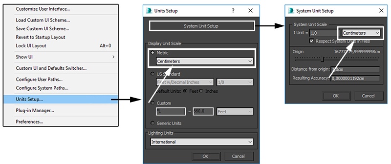
Units Setup
|
Units Setup
...
...
| Section | ||||||||||
|---|---|---|---|---|---|---|---|---|---|---|
|
...
| Section | ||||||||||
|---|---|---|---|---|---|---|---|---|---|---|
|
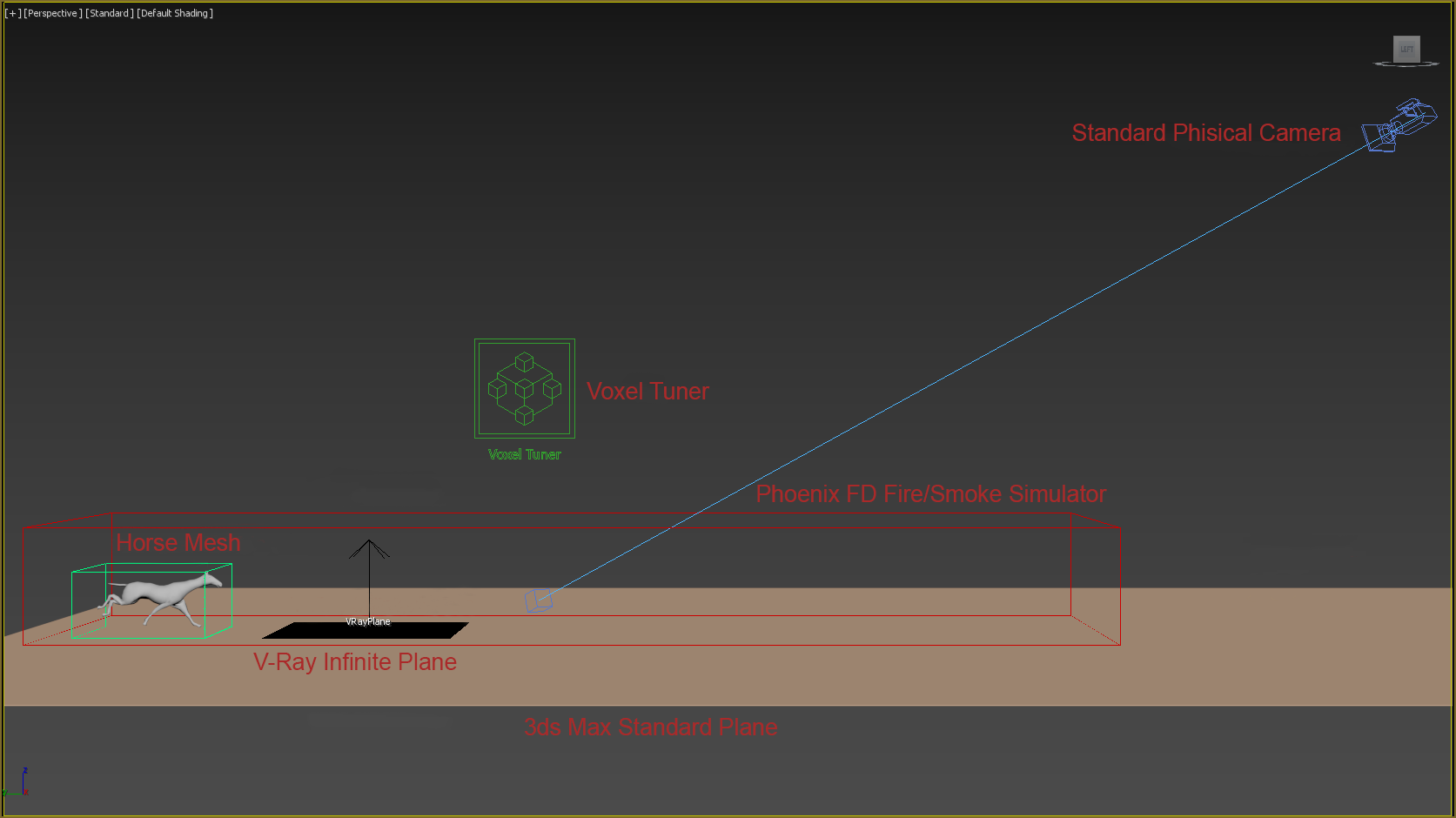
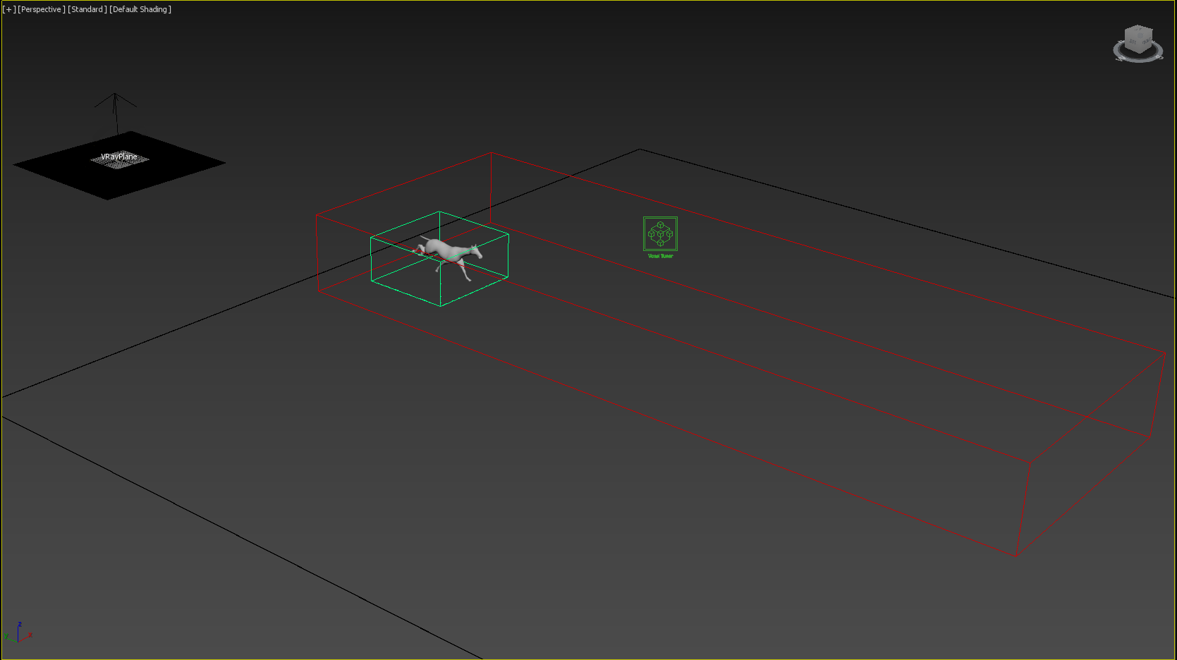
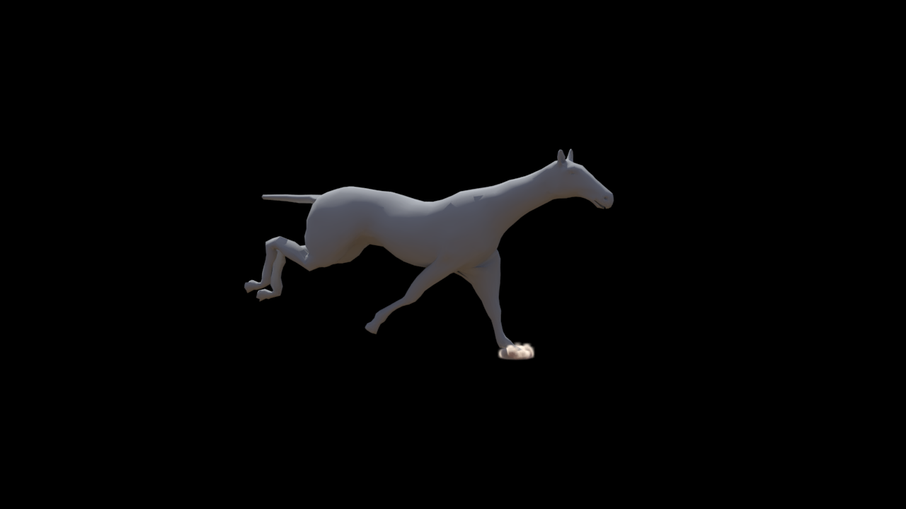
Scene Layout
...
...
| Section | ||||||||||
|---|---|---|---|---|---|---|---|---|---|---|
|
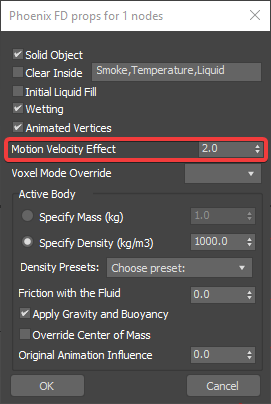
Scene Setup
...
| Section | ||||||||||
|---|---|---|---|---|---|---|---|---|---|---|
|
...
| Section | ||||||||||
|---|---|---|---|---|---|---|---|---|---|---|
|
| Section | |||||||||||||||
|---|---|---|---|---|---|---|---|---|---|---|---|---|---|---|---|
|
|
...
| Section | |||||
|---|---|---|---|---|---|
|
...
...
| Section | ||||||||||
|---|---|---|---|---|---|---|---|---|---|---|
|
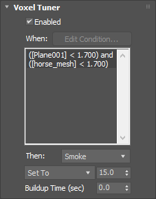
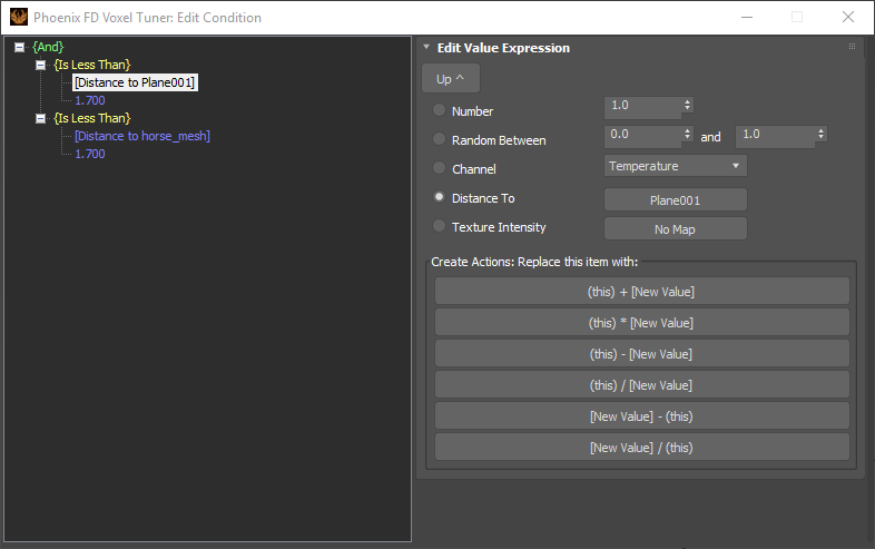
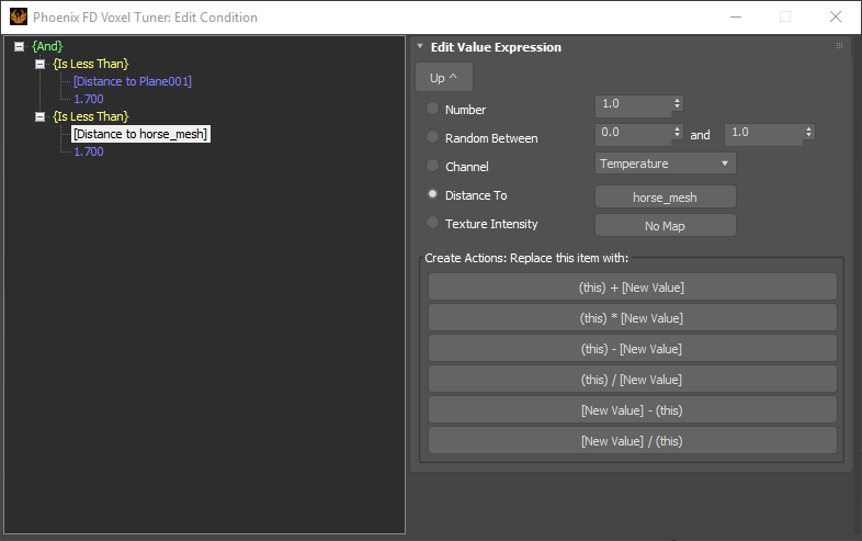
Voxel Tuner
...
| Section | ||||||||||
|---|---|---|---|---|---|---|---|---|---|---|
|
| Section | |||||||||||||
|---|---|---|---|---|---|---|---|---|---|---|---|---|---|
|
...
| Section | ||||||||||
|---|---|---|---|---|---|---|---|---|---|---|
|
Simulation
...
| Section | |||||||||
|---|---|---|---|---|---|---|---|---|---|
|
| Section | ||||||||||
|---|---|---|---|---|---|---|---|---|---|---|
|
| Section | ||||||||||
|---|---|---|---|---|---|---|---|---|---|---|
|
Simulation
| Section | ||||||||||
|---|---|---|---|---|---|---|---|---|---|---|
|
| ||||||||||
| Section | ||||||||||
|---|---|---|---|---|---|---|---|---|---|---|
|
...
| Section | ||||||||||
|---|---|---|---|---|---|---|---|---|---|---|
|
...
| Section | ||||||||||
|---|---|---|---|---|---|---|---|---|---|---|
|
...
| Section | ||||||||||
|---|---|---|---|---|---|---|---|---|---|---|
|

...
| Section | ||||||||||
|---|---|---|---|---|---|---|---|---|---|---|
|
...
| Section | ||||||||||
|---|---|---|---|---|---|---|---|---|---|---|
|
...
| Section | ||||||||||
|---|---|---|---|---|---|---|---|---|---|---|
|
...
| Section | ||||||||||
|---|---|---|---|---|---|---|---|---|---|---|
|
...
| Section | ||||||||||
|---|---|---|---|---|---|---|---|---|---|---|
|
...
| Section | ||||||||||
|---|---|---|---|---|---|---|---|---|---|---|
|
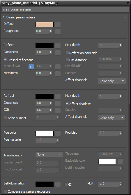
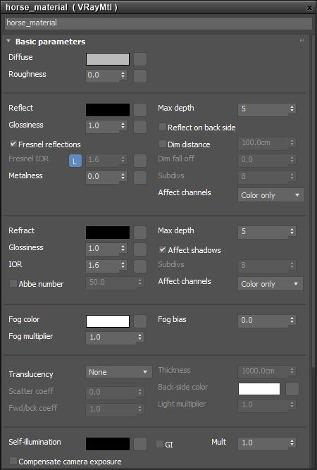
Materials
...
| Section | ||||||||||
|---|---|---|---|---|---|---|---|---|---|---|
|
...
| Section | ||||||||||
|---|---|---|---|---|---|---|---|---|---|---|
|
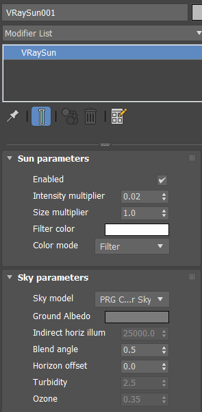
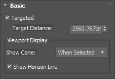
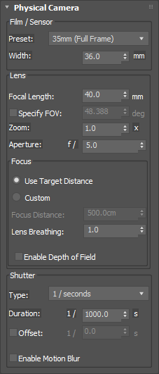
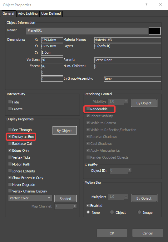
Lighting and Camera
...
| Section | ||||||||||
|---|---|---|---|---|---|---|---|---|---|---|
|
...
| Section | ||||||||||
|---|---|---|---|---|---|---|---|---|---|---|
|
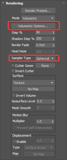
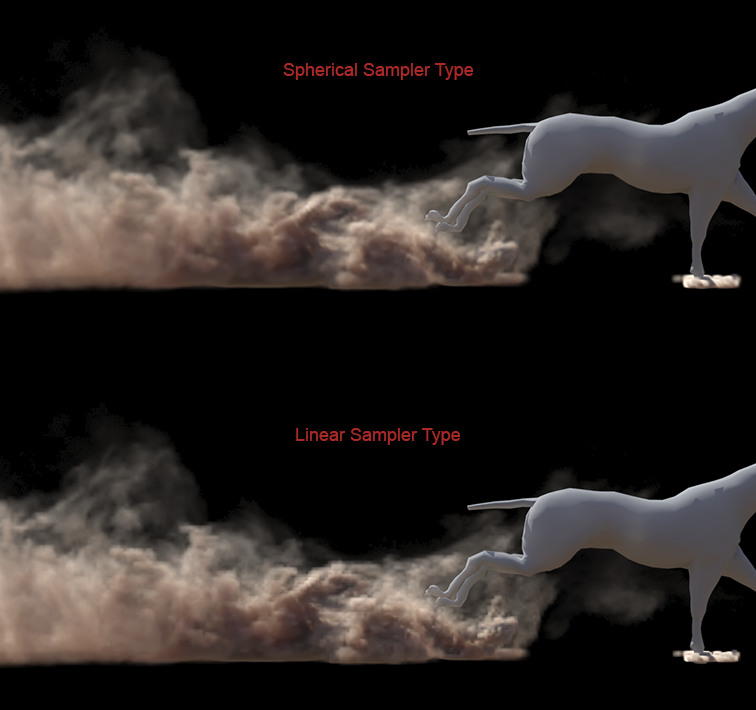
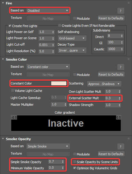
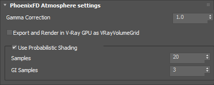
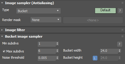
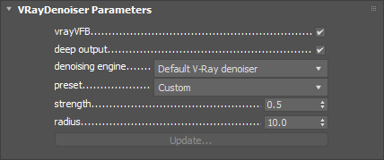
Render Settings
...
| Section | ||||||||||
|---|---|---|---|---|---|---|---|---|---|---|
|
...
| Section | ||||||||||
|---|---|---|---|---|---|---|---|---|---|---|
|
...
| Section | ||||||||||
|---|---|---|---|---|---|---|---|---|---|---|
|
...
| Section | |||||||||||
|---|---|---|---|---|---|---|---|---|---|---|---|
|
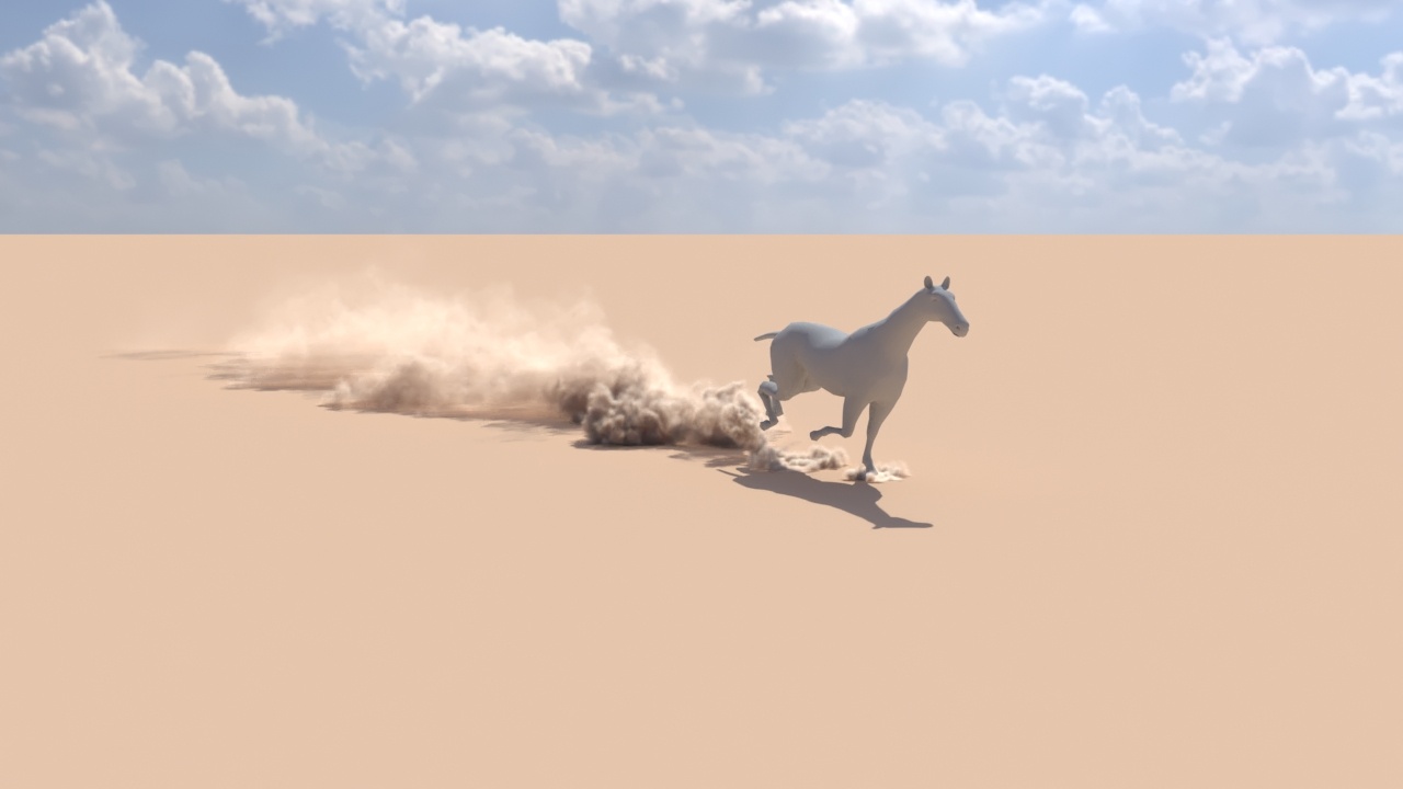
Final Results
...
| Section | |||||||||||
|---|---|---|---|---|---|---|---|---|---|---|---|
|
|
...