![]()
Page History
...
| UI Text Box | ||
|---|---|---|
| ||
UI Path: ||Select Liquid Simulator object|| > Modify panel > Grid rollout |
Parameters
...
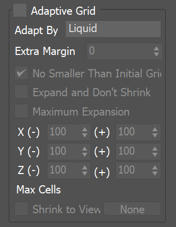
General
...
| Section | |||||||||||||||||||||||
|---|---|---|---|---|---|---|---|---|---|---|---|---|---|---|---|---|---|---|---|---|---|---|---|
|
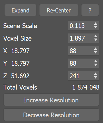
Example: Scene Scale
...
| UI Text Box | ||
|---|---|---|
| ||
The following video provides examples to show the differences of Scene Scale with values of 0.1, 5.0 and 15.0. |
| Align | ||
|---|---|---|
| ||
|
Software used: Phoenix FD 4.30.01 Nightly (02 Oct 2020)
| UI Button | ||||||||
|---|---|---|---|---|---|---|---|---|
|
| Anchor | ||||
|---|---|---|---|---|
|
...
...
...
| UI Text Box | ||
|---|---|---|
| ||
The following video provides examples to show the differences when the Total cells from the Grid's Resolution is atat 570,000, 4,000,000and 16,000,000. |
| Align | ||
|---|---|---|
| ||
|
Software used: Phoenix FD 4.30.01 Nightly (02 Oct 2020)
| UI Button | ||||||||
|---|---|---|---|---|---|---|---|---|
|
| Anchor | ||||
|---|---|---|---|---|
|
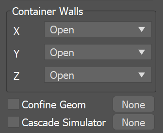
Container Walls
...
| Section | |||||||||||||||||||||||||||||||||
|---|---|---|---|---|---|---|---|---|---|---|---|---|---|---|---|---|---|---|---|---|---|---|---|---|---|---|---|---|---|---|---|---|---|
|
| Anchor | ||||
|---|---|---|---|---|
|
...
| Section | |||||||||||||||||||||||||||
|---|---|---|---|---|---|---|---|---|---|---|---|---|---|---|---|---|---|---|---|---|---|---|---|---|---|---|---|
|