![]()
Page History
...
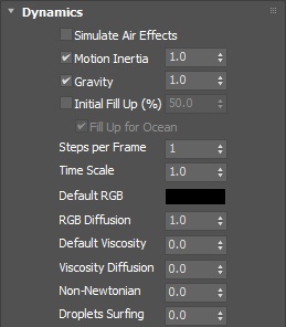
This rollout controls the fluid's motion parameters.
| UI Text Box | ||||
|---|---|---|---|---|
| ||||
UI Path: ||Select Liquid Simulator | LiquidSim object|| > Modify panel > Dynamics rollout |
...
Parameters
...
Simulate Air Effects | simair – When enabled, turns on the built-in air simulator for the areas in the simulation grid which are not full of liquid. The air velocity can be affected by the liquid movement, by Sources, or by fast moving obstacles inside the Simulator. In turn, the air velocity will affect and carry splash, mist, and foam particles. Note, however, that no matter how strong the air velocity is, it will not affect the liquid back. So for example you can use Simulate Air Effects when realistic mist is needed in waterfall setups, or stormy ocean scenes. The air simulation can dramatically increase the quality of splash and mist effects.
| UI Text Box | size | medium|
|---|---|---|
| ||
The air effects stop affecting particles once they exit the Simulator thus altering the particle speed and direction around the Simulator's walls. |
| Anchor | ||||
|---|---|---|---|---|
|
| UI Text Box | |||
|---|---|---|---|
| |||
When running liquid simulations with the Initial Fill Up option and Open Container Wall conditions, the surface of the generated liquid should remain smooth. If you encounter artifacts in the form of horizontal lines perpendicular to the direction of movement, with Motion Inertia enabled, please ensure that the Scene Scale is reasonable considering the type of effect being simulated. Other possible solutions in case tweaking the scale is not possible are to either increase the Steps Per Frame, or to reduce the Cell Size of the Simulator. Liquid artifacts usually appear when the liquid particles move a great distance between frames. Increasing the Scene Scale or the Steps Per Frame allows them to stabilize, which in turn keeps the surface smooth. |
...
Initial Fill Up | initfill, flevel – When enabled, the container is filled up with liquid when the simulation starts. This option determines the fill-up level, measured in % of the vertical Z size of the Grid. For liquid simulations using Confine Geometry, you can enable Clear Inside on the geometry and liquid will not be created at simulation startup in the voxels inside the geometry.Anchor InitialFillUp InitialFillUp
| UI Text Box | |||
|---|---|---|---|
| |||
The liquid created through the Initial Fill Up option will be initialized with the values set for the Default RGB and Default Viscosity parameters below. |
...
In order to eliminate air pockets between Solid geometry and the liquid mesh, this option will automatically set all Solid voxels below the Initial Fill Up level to contain Liquid amount of 1, even if they don't contain any Liquid particles. If you don't want this effect, enable Clear Inside from the Chaos Phoenix FD PropertiesPer-Node Properties of the Solid geometry. See the Fill Up For Ocean and Clear Inside example below.
| UI Text Box | |||
|---|---|---|---|
| |||
All Simulator walls must be set to Open from the Grid rollout for Fill Up For Ocean to take effect. |
| Anchor | ||||
|---|---|---|---|---|
|
| UI Text Box | size | medium|
|---|---|---|
| ||
One of the most important parameters of the Simulator, with significant impact on quality and performance. To understand how to use it, keep in mind that the simulation is a sequential process and happens step by step. It produces good results if each simulation step introduces small changes, but it's also a trade-off between performance and detail, as described below. For example let's take an object that is hitting the liquid surface with high speed. If at the first step the object is far away from the water and at the second step, the object is already deep under the water - the result won't look good. You have to introduce intermediate steps until the changes of each step get small enough. The Steps Per frame option creates these steps within each frame. A value of 1 means that there are no intermediate steps and each step is exported into the cache file. A value of 2 means that there is one intermediate step, i.e. each second step is exported to the cache file while the intermediate steps are just calculated, but not exported. Signs that the Steps Per Frame need to be increased are:
More often than not, those issues will be caused by the simulation moving too quickly (e.g. the emission from the source is very strong or the objects in the scene are moving very fast). In such cases you should use a higher SPF. Keep in mind that higher Steps Per Frame decreases the performance in a linear way, i.e. if you increase the SPF twice, your simulation will go twice as slow. However, the quality does not have a linear relation to the SPF. Each simulation step kills fine details, and thus for maximum detail it's best to use the lowest possible SPF that runs without any of the issues mentioned above. For additional information, please refer to Phoenix Explained. |
Time Scale | timescale – Specifies a time multiplier that can be used for slow motion effects. For more information, see the Time Scale example below.
| UI Text Box | size | medium|
|---|---|---|
| ||
In order to achieve the same simulation look when changing the Time Scale, the Steps Per Frame value must be changed accordingly. For example, when decreasing the Time Scale from 1.0 to 0.5, Steps Per Frame must be decreased from 4 to 2. All animated objects in the scene (moving objects and sources) must be adjusted as well. Time Scale different than 1 will affect the Buildup Time of Particle/Voxel Tuners and the Phoenix Mapper. In order to get predictable results you will have to adjust the buildup time using this formula: |
Default RGB | lq_default_rgb - The Simulator is filled with this RGB color at simulation start. The Default RGB is also used to color the fluid generated by Initial Fill Up, or by Initial Liquid Fill from the Phoenix FD Properties of Chaos Phoenix Per-Node Properties of a geometry - both of these options create liquid only at the start of the simulation. During simulation, more colors can be mixed into the sim by using a Phoenix FD Liquid Source with RGB enabled, or the color of existing fluid can be changed over time by using a Phoenix FD MapperPhoenix Mapper. If a Phoenix FD Liquid Source does not have RGB enabled, it also emits using the Default RGB value.
| UI Text Box | |||
|---|---|---|---|
| |||
The RGB Grid Channel has to be enabled in the Output Rollout for this parameter to take effect. |
...
Default Viscosity | lqvisc – Determines the default viscosity of the liquid. Viscosity means how thick the liquid is. Liquids such as honey, syrup, or even thick mud and lava need to be simulated with high viscosity. On the other hand, liquid such as water, beer, coffee or milk are very thin and show have zero or very low viscosity. The Default Viscosity value is used when no viscosity information for the emitted liquid is provided to the Simulator by the Source. For more information, see the Viscosity example below.Anchor Viscosity Viscosity
| UI Text Box | |||
|---|---|---|---|
| |||
|
Viscosity Diffusion | viscdiff - Phoenix FD supports Phoenix supports sourcing of fluids with different viscosity (thickness) values. This parameter specifies how quickly they blend together. A low value will preserve the distinct viscosities, while a high value will allow them to mix together and produce a fluid with a uniform thickness.
...
| Section | ||||||||||||||||||||||||
|---|---|---|---|---|---|---|---|---|---|---|---|---|---|---|---|---|---|---|---|---|---|---|---|---|
Example: Motion Inertia
Software used: Phoenix FD 4.30.01 Nightly (02 Oct 2020)
|
...
Example: Fill Up For Ocean and Clear Inside
...
| UI Text Box | ||||
|---|---|---|---|---|
| ||||
This example shows the Liquid voxels, with a submerged Solid ellipsoid. There are never FLIP particles inside it, but disabling Clear Inside will fill it with Liquid voxels so the liquid mesh can intersect it. |
...
| Section | ||||||||||||||||||||||||
|---|---|---|---|---|---|---|---|---|---|---|---|---|---|---|---|---|---|---|---|---|---|---|---|---|
Example: Steps Per Frame
Software used: Phoenix FD 4.30.01 Nightly (02 Oct 2020)
|
...
| Section | ||||||||||||||||||||||||
|---|---|---|---|---|---|---|---|---|---|---|---|---|---|---|---|---|---|---|---|---|---|---|---|---|
Example: Time Scale
Software used: Phoenix FD 4.30.01 Nightly (02 Oct 2020)
|
...
| Section | ||||||||||||||||||||||||
|---|---|---|---|---|---|---|---|---|---|---|---|---|---|---|---|---|---|---|---|---|---|---|---|---|
Example: Viscosity
Software used: Phoenix FD 4.30.01 Nightly (02 Oct 2020)
|
...
| Section | ||||||||||||||||||||||||
|---|---|---|---|---|---|---|---|---|---|---|---|---|---|---|---|---|---|---|---|---|---|---|---|---|
Example: Non-Newtonian
Software used: Phoenix FD 4.30.01 Nightly (02 Oct 2020)
|
...
| Section | ||||||||||||||||||||||||
|---|---|---|---|---|---|---|---|---|---|---|---|---|---|---|---|---|---|---|---|---|---|---|---|---|
Example: RGB Diffusion
Software used: Phoenix FD 4.30.01 Nightly (02 Oct 2020)
|
...
Droplet Radius | lqstdroprad – Controls the radius of the droplets formed by the Droplet Breakup parameter, in voxels. This means that increasing the resolution of the Simulator will reduce the overall size of the droplets in your simulation.
| UI Text Box | ||||
|---|---|---|---|---|
| ||||
Increasing the Droplet Radius can dramatically slow down the simulation. Please use it with caution. |
...
| Section | ||||||||||||||||||||||||
|---|---|---|---|---|---|---|---|---|---|---|---|---|---|---|---|---|---|---|---|---|---|---|---|---|
Example: Surface Tension
Software used: Phoenix FD 4.30.01 Nightly (02 Oct 2020)
|
...
| Section | ||||||||||||||||||||||||
|---|---|---|---|---|---|---|---|---|---|---|---|---|---|---|---|---|---|---|---|---|---|---|---|---|
Example: Droplet Breakup
Software used: Phoenix FD 4.30.01 Nightly (02 Oct 2020)
|
...
| Anchor | ||||
|---|---|---|---|---|
|
Wetting
...
| UI Text Box | ||||
|---|---|---|---|---|
| ||||
Simulation of wetting can be used in rendering for blending of wet and dry materials depending on which parts of a geometry have been in contact with the simulated liquid. Wetting can also change the behavior of simulated viscous liquid and make it stick to geometries. The wetting simulation produces a particle system called WetMap. It can be rendered using a Particle Texture map which blends between a wet and a dry surface material. |
...
Sticky Liquid | wetdyn – This option produces a connecting force between the WetMap particles at the geometry surface and nearby liquid particles, when the liquid particles have at least a little Viscosity. For more information, see the Sticky Liquid example below.
| UI Text Box | size | medium|
|---|---|---|
| ||
Geometry transforming or deforming at a high velocity may cause some or all of the Wetting particles stuck to it to disappear. To resolve this, dial up the Steps Per Frame parameter from the Dynamics tab of the Simulator. |
...
| Section | ||||||||||||||||||||||||
|---|---|---|---|---|---|---|---|---|---|---|---|---|---|---|---|---|---|---|---|---|---|---|---|---|
Example: Consumed Liquid
Software used: Phoenix FD 4.30.01 Nightly (02 Oct 2020)
|
...
| Section | ||||||||||||||||||||||||
|---|---|---|---|---|---|---|---|---|---|---|---|---|---|---|---|---|---|---|---|---|---|---|---|---|
Example: Sticky Liquid without Viscosity
Software used: Phoenix FD 4.30.01 Nightly (02 Oct 2020)
|
...
| Section | ||||||||||||||||||||||||
|---|---|---|---|---|---|---|---|---|---|---|---|---|---|---|---|---|---|---|---|---|---|---|---|---|
Example: Sticky Liquid and Viscosity
Software used: Phoenix FD 4.30.01 Nightly (02 Oct 2020)
|
...
| Section | ||||||||||||||||||||||||
|---|---|---|---|---|---|---|---|---|---|---|---|---|---|---|---|---|---|---|---|---|---|---|---|---|
Example: Sticky Liquid with different amount of fluid
Software used: Phoenix FD 4.30.01 Nightly (02 Oct 2020)
|
Active Bodies
...
| UI Text Box | ||||
|---|---|---|---|---|
| ||||
The Active Bodies simulation currently supports interaction between scene geometry and the Phoenix FD Liquid Simulator. When an object is selected as an Active Body, the simulation both influences and is influenced by the Active Body's movement. Mutual interaction between the Active Bodies themselves is not supported yet. Interaction between Active Bodies and the Phoenix FD Fire/Smoke Simulator is not supported. For in-depth information on Active Bodies, please check the Active Bodies Setup Guide. |
...
Active Body Solver | activeBodySolverNode – Specifies the Active Body Solver node holding the objects to be affected by the Phoenix FD SimulationPhoenix Simulation.
Texture UVW
...
| UI Text Box | ||||
|---|---|---|---|---|
| ||||
The main purpose of the Texture UVW feature is to provide dynamic UVW coordinates for texture mapping that follow the simulation. If such simulated texture coordinates are not present for mapping, textures assigned to your simulation will appear static, with the simulated content moving through the image. This undesired behavior is often referred to as 'texture swimming'. UVW coordinates are generated by simulating an additional Texture UVW Grid Channel which has to be enabled under the Output rollout for the settings below to have any effect. The custom UVW texture coordinates can be used for advanced render-time effects, such as recoloring of mixing fluids, modifying the opacity or fire intensity with a naturally moving texture, or natural movement of displacement over fire/smoke and liquid surfaces. Some examples uses are:
The Texture UVW channel values represent the UVW coordinates of each Cell in the Simulator, with a range of [ 0 - 1 ]. The channel is initialized when a simulation is started in one of two ways:
|
...
| Section | ||||||||||||||||||||||||
|---|---|---|---|---|---|---|---|---|---|---|---|---|---|---|---|---|---|---|---|---|---|---|---|---|
Example: Interpolation
Software used: Phoenix FD 4.30.01 Nightly (02 Oct 2020)
|
...
| Section | ||||||||||||||||||||||||
|---|---|---|---|---|---|---|---|---|---|---|---|---|---|---|---|---|---|---|---|---|---|---|---|---|
Example: Interpolation Step
Software used: Phoenix FD 4.30.01 Nightly (02 Oct 2020)
|