![]()
Page History
...
| Div | ||||||||||||||
|---|---|---|---|---|---|---|---|---|---|---|---|---|---|---|
| ||||||||||||||
The rendering process in Chaos Phoenix FD is separated from the simulation, but for ease of operation is performed by the same object that performs the simulation. However, this is only true for the grid's content, not for the particles contained in the cache file.
|
Phoenix FD has Phoenix has multiple rendering modes that can be divided into two types: volumetric and surfaces. The volumetric modes are used for fire and smoke. 3ds Max materials can't be used to shade volumetrics because they don't have surfaces. Instead their shading is described in the Volumetric Render Settings window. Unlike the volumetric modes, in surface modes the Simulator behaves just as any regular geometry - 3ds Max materials can be applied to the Simulator and there is no need for a dedicated shader.
Advanced control over the shading is provided with the Grid Texture which can be used to drive the properties of a material applied to the Phoenix mesh or isosurface. For Volumetric rendering, Phoenix FD provides Phoenix provides you with the ability to drive the color and opacity of Fire / Smoke simulations through any of the supported channels (such as Smoke, Speed, RGB, etc.), as long as they are present in the cache files.
Phoenix FD also Phoenix also provides you with the option to generate a mesh surface based on any of the supported channels. Thus, a Smoke simulation can be rendered as a polygon mesh with a custom material applied to it, which can be used for effects such as freezing flame or cartoon-style smoke.
| UI Text Box | size | medium|
|---|---|---|
| ||
UI Path: ||Select Fire Smoke Simulator | FireSmokeSim object|| > Modify panel > Rendering rollout |
...

Render Presets... – Opens a menu for loading and saving different presets. The following options are available:
| Fancy Bullets | ||
|---|---|---|
| ||
|
| Anchor | ||||
|---|---|---|---|---|
|
Mode | rendmode – Specifies the method for visualizing the grid content.
Volumetric – Visualizes the content as a standard 3ds Max atmospheric. This method is used mostly for fire and smoke.
| Anchor | ||||
|---|---|---|---|---|
|
| UI Text Box | size | medium|
|---|---|---|
| ||
Approximate and Approximate+Shadows options for the Scattering parameter in the Smoke color window are not supported in Volumetric Geometry mode. For a complete list of the supported Render Elements in both Volumetric and Volumetric Geometry mode, please check the V-Ray Render Elements Support page. |
Volumetric Heat Haze – This method requires V-Ray. It produces the same result as the Volumetric Geometry option, and also adds a heat haze effect when used with the Heat Haze parameter. Note that you might need to increase the Max depth of a VRayMtl with refraction in case it intersects with the Heat Haze shader.
| Anchor | ||||
|---|---|---|---|---|
|
Mesh – The content is converted into a standard 3ds Max mesh using the Surface section options. This mode is mostly used for liquids, but can also be applied to thick smoke using a scatter material or to plumes of smoke to create effects such as large underwater bubbles.
Ocean Mesh – The grid content is extended to a flat area, fitting the camera's view. In most cases, this mode is used with a displacement texture such as the Phoenix FD Ocean Texture.
Cap Mesh – Only the upper liquid surface is rendered. This mode can be used for swimming pools and other placid liquid surfaces.
| UI Text Box | |||
|---|---|---|---|
| |||
The ocean surface can be generated only when the liquid touches the sides and the bottom of the grid, which act as a container for the liquid. The detail of the mesh extension around the simulator depends on the camera resolution - for each pixel of the viewport or the rendered image, one or several polygons are generated, depending on the Ocean Subdivisions option. |
| Div | ||||
|---|---|---|---|---|
| ||||
Volumetric Options... – Opens the Volumetric Render settings window which contains the following rollouts:
|
Parameters
...
...

| Anchor | ||||
|---|---|---|---|---|
|
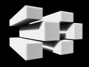
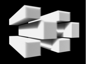
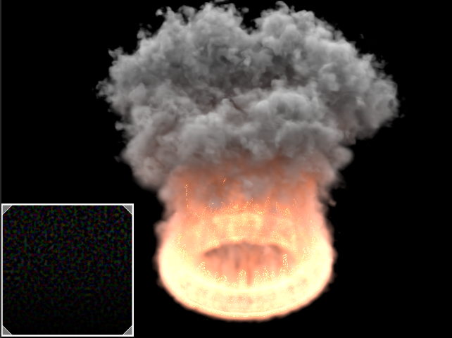
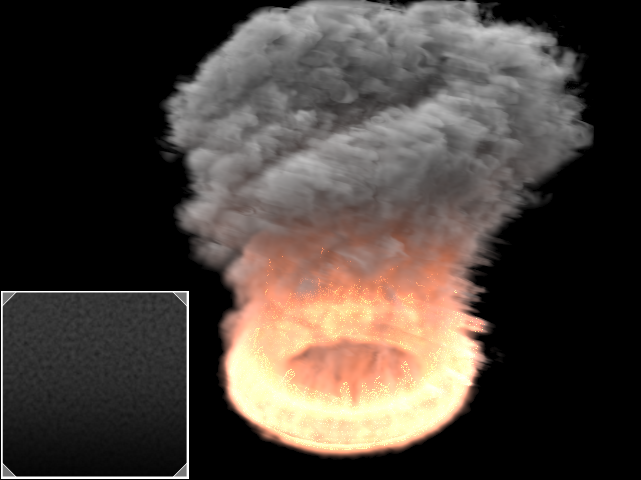
Step % | rendstep – Specifies the ray marching step of the camera rays as a percentage of the cell size. As the renderer traces rays through the Simulator, this value controls how often to read information from the grid. If this value is more than 100, some cells will start getting skipped and artifacts may appear. Usually you don't need to lower this below 90%, unless you use render curves or texture maps for the Fire or Smoke opacity or color - in these cases you might need to lower the step in order to capture the details which are smaller than a voxel, otherwise these details will either be skipped or will render very noisy. However, decreasing the step will make the render slower. This parameter is used when Mode is set to Volumetric, Volumetric Geometry, Volumetric Heat Haze or Isosurface. See the Step % example below.
...
Invert Cutter | invgizmo – When enabled, rendering will occur only outside of the render cutter. This is not the same as a cutter with inverted geometry because any rays that do not intersect the cutter will be shaded as well.
| UI Text Box | size | medium|
|---|---|---|
| ||
If using a Cutter Geom for a liquid pouring into a glass or otherwise contained into another refractive object, you may need to set the Mode to Isosurface. By default, the mode is set to Mesh which may produce artifacts in the rendered image. |
| Anchor | ||||
|---|---|---|---|---|
|
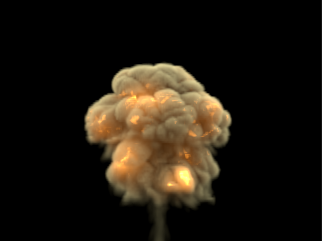
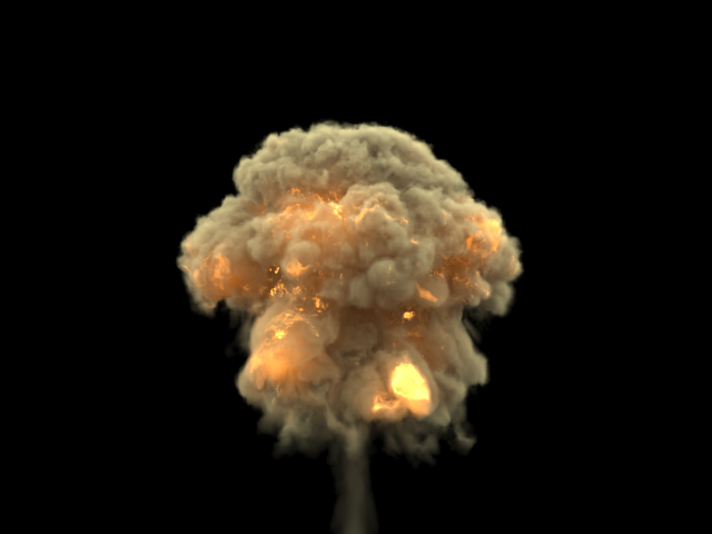
Example: Step %
...
| UI Text Box | size | medium|
|---|---|---|
| ||
This example shows how the Step % value can be used to improve the quality of the ray-marching. |
| Section | ||||||||||||||||||||
|---|---|---|---|---|---|---|---|---|---|---|---|---|---|---|---|---|---|---|---|---|
| ||||||||||||||||||||
|
| Anchor | ||||
|---|---|---|---|---|
|
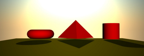
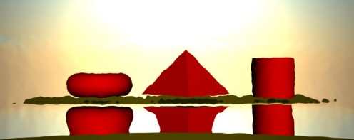
Example: Heat Haze
...
...
| UI Text Box | size | medium|
|---|---|---|
| ||
Heathaze Heat Haze adds refraction at each ray-marching step through the volume. This only affects the camera's view. Heat haze Haze will not affect shadows cast through a volume. |
| Section | ||||||||||||||||||||
|---|---|---|---|---|---|---|---|---|---|---|---|---|---|---|---|---|---|---|---|---|
| ||||||||||||||||||||
|
| Anchor | ||||
|---|---|---|---|---|
|
Surface
...
| UI Text Box | size | medium|
|---|---|---|
| ||
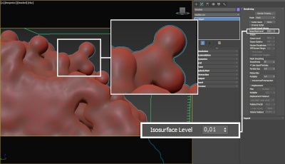
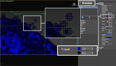
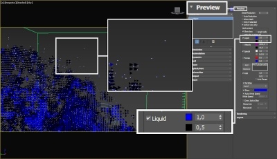
This section controls the conversion of the grid content into geometry. If Mode is set to Mesh, Ocean Mesh, Cap Mesh or Isosurface, the Surface channel needs to be set and an appropriate Isosurface Level must be chosen from this section. The controls in this section also denote the surface used in Gradient and Surface-driven displacement. This way it can affect all render modes, not just the surface modes. The technique for generating the surface is based on the isosurface concept. The resulting surfaces are mostly used to render liquids, but can be used for smoke and fire as well to create effects like underwater bubbles, freezing fire, etc. |
...
| Anchor | ||||
|---|---|---|---|---|
|
| UI Text Box | size | medium|||||||||||||||||||||||||||||||||
|---|---|---|---|---|---|---|---|---|---|---|---|---|---|---|---|---|---|---|---|---|---|---|---|---|---|---|---|---|---|---|---|---|---|---|
| ||||||||||||||||||||||||||||||||||
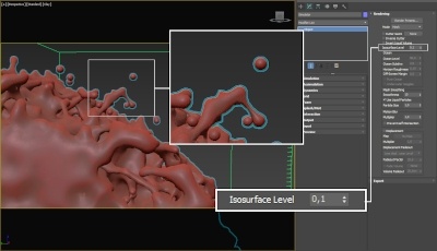
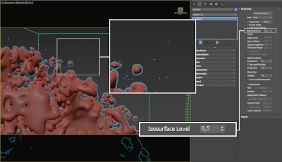
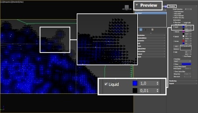
The proper value for the Isosurface Level parameter depends on the numerical range of the surface channel. For example, Phoenix FD liquids are kept in the range of 0 to 1. A value of 0 means there is no liquid in a certain voxel, and a value of 1 means the cell is 100% full of liquid. Values in between indicate a certain mixture of air and liquid. For such cache files, an Isosurface Level value of 0.5 is best for visualizing the surface between the air and liquid. Imported caches from Houdini, on the other hand, use positive and negative values to indicate whether a voxel is inside or outside the liquid volume, so a correct "halfway" Isosurface Level value would be 0.0. For Phoenix FD smoke, the proper value is about 0.01, and for Phoenix FD temperature, which is in Kelvins, the value is several hundred. Please check the Grid Channel Ranges page for information about other grid channels.
|
Motion Blur
...
| UI Text Box | size | medium|
|---|---|---|
| ||
To render your Volumetric Simulation with Motion Blur, you need to enable Velocity channel export from the Output tab of your simulator. |
...
Prevent self intersection | mbself – The motion blur of the mesh is obtained by shifting each vertex toward the velocity by the shutter time. In certain cases the shifted vertex may penetrate the opposite side of the geometry, causing problems in the rendering. When enabled, this option prevents such situations. The self-intersection analysis is expensive, so enable this parameter only when the issue is noticeable.
| UI Text Box | size | medium|
|---|---|---|
| ||
Phoenix FD meshes are motion blurred in a different way than regular transforming and deforming geometries. When rendering regular meshes with motion blur, the entire mesh is moved along its transformation path back and forward in time, and so each individual vertex of the mesh follows this path. However, for each rendered frame, a new Phoenix mesh must be built from the voxel grid, and so it usually has a different number of vertices than the previous and the next frame. Because of this, individual vertices can not be traced back or forward in time between frames. Instead, motion blur of fluid meshes uses the velocity of vertices which is recorded by the simulation, and moves each vertex back and forward in time along the vertex velocity. This is why the generated liquid mesh does not support frame sub-sampling for motion blur. This may cause a mis-match mismatch between the liquid and transforming/deforming objects in your scene that interact with it. The fluid mesh is generated from data at the exact rendered frame and fluid data for the preceding or following frames is not used, unlike regular deforming meshes. As a consequence, the liquid and the objects in your scene would synchronize best if those objects do not use additional geometry samples for motion blur. |
Displacement
...
| UI Text Box | size | medium|
|---|---|---|
| ||
Displacement is a technique intended to add detail to the simulation during the rendering. The idea of the Phoenix displacement is similar to the usual geometry displacement: a texture is sampled, and the corresponding point of the fluid volume or surface is shifted in a direction at a distance determined by the texture. You can plug any V-Ray, 3ds Max or Phoenix texture maps. |
...
Enable | displacement, displmul – Enables the displacement effect, and enables the use of a multiplier value to increase or decrease the overall displacement effect.
| UI Text Box | size | medium|
|---|---|---|
| ||
The Type parameter is ignored when Mode is set to Mesh, Ocean Mesh or Cap Mesh. In these modes Phoenix automatically recognizes whether the texture map is monochrome or colored and uses respectively Surface-driven or Vector displacement. The difference between Surface driven and Vector displacement is that vector displacement can produce more complicated surfaces. For example, a wave texture in Vector mode produces waves that have a convex back side and a concave front side, in contrast with the symmetrical forms produced by Surface driven displacement. |
...
Example: Advection Displacement
...
...
| Section | ||||||||||||||||||||
|---|---|---|---|---|---|---|---|---|---|---|---|---|---|---|---|---|---|---|---|---|
|
| Anchor | ||||
|---|---|---|---|---|
|
Example: Advection Displacement with a Monochrome Map
...
...
| UI Text Box | size | medium|
|---|---|---|
| ||
This example illustrates how displacement is affected when a monochrome map is passed when a vector map is needed. |
| Section | ||||||||||||||||||||
|---|---|---|---|---|---|---|---|---|---|---|---|---|---|---|---|---|---|---|---|---|
|
...
|