![]()
Page History
...
| Div | ||||
|---|---|---|---|---|
| ||||
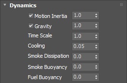
This rollout controls the FireSmoke dynamics parameters. It can be accessed in the Modify panel when a FireSmokeSim object is selected. |
| UI Text Box | ||||
|---|---|---|---|---|
| ||||
UI Path: ||Select Fire Smoke Simulator | FireSmokeSim|| > Modify panel > Dynamics rollout |
Parameters
...
General
...
...
| Anchor | ||||
|---|---|---|---|---|
|
...
| Div | |||||||
|---|---|---|---|---|---|---|---|
| |||||||
Cooling | cooling – This parameter controls the cooling of the fluid due to radiation. It gradually decreases the temperature until it reaches 300.
|
...
| Anchor | ||||
|---|---|---|---|---|
|
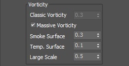
Vorticity
...
...
| Div | ||||
|---|---|---|---|---|
| ||||
Classic Vorticity | vorticity – Adds small-scale detail that is dissipated naturally by the grid-based simulation. Prevents the simulation from becoming smooth and laminar. Unlike Turbulence, which does not care about the fluid's motion at all, the Classic Vorticity algorithms works depending on the velocity of the simulation and changes the velocity field in order to reinforce vortices and add more detail to the simulation.For more information, see the Vorticity example below. |
...
| Section | ||||||||||||||||||||||||||||||||||
|---|---|---|---|---|---|---|---|---|---|---|---|---|---|---|---|---|---|---|---|---|---|---|---|---|---|---|---|---|---|---|---|---|---|---|
Example: Vorticity
|


Randomize
...
| Div | ||||
|---|---|---|---|---|
| ||||
These options add random fluctuations in the fluid's velocity for each grid voxel. It works in combination with the Vorticity parameters. |
...
| Div | ||||
|---|---|---|---|---|
| ||||
The conservation process gives the fluid its characteristic swirling motion. It transforms straight-line movement of the fluid into swirling vortices. The higher the strength of the conservation, the farther the motion forces will be propagated throughout the container, so a movement in one point will cause the fluid to start moving at a distance too. The conservation directs smoke and fire into realistic shapes and helps liquids to support their own weight when at rest, and to fill up a volume they are poured into. |
| UI Text Box | size | medium|
|---|---|---|
| ||
Internally, the conservation updates the directions and magnitudes of the velocities of each cell in the grid, preparing them for the Advection step when the content will be moved between cells. Basically it tries to equalize the velocities coming in and going out from each cell, and does this in many passes, getting closer to the perfect equilibrium. The number of passes is the conservation strength (quality). In nature, conservation has an infinite strength and is always perfect. In Phoenix FD, the better the quality of the conservation is, the farther the movement from one point will be propagated, making the simulation more realistic, but at the expense of longer simulation time for each frame. There are a number of conservation methods in Phoenix FD that you can choose between, depending on the type of your simulation. Each of them comes with pros and cons for the given situation. |
...
| Section | ||||||||||||||||||||||||||||||||||
|---|---|---|---|---|---|---|---|---|---|---|---|---|---|---|---|---|---|---|---|---|---|---|---|---|---|---|---|---|---|---|---|---|---|---|
Example: Conservation Method Types
|
| Anchor | ||||
|---|---|---|---|---|
|
| Section | ||||||||||||||||||||||||||||||||||||
|---|---|---|---|---|---|---|---|---|---|---|---|---|---|---|---|---|---|---|---|---|---|---|---|---|---|---|---|---|---|---|---|---|---|---|---|---|
Example: Conservation Quality
|


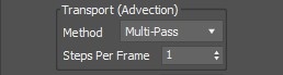
Anchor Advection Advection
...
The advection process moves the fluid along its velocity inside the grid. A problem of all grid-based simulators is that moving the content of one cell to a new place in the grid will blur the result when the destination lies between cells (and it usually does), thus losing the fine details with each new frame. Phoenix FD has a number of advection methods that battle this problem in different ways, each one with its own pros and cons depending on the situation.
| UI Text Box | ||||
|---|---|---|---|---|
| ||||
Phoenix FD may perform advection more than once per frame, or once in a number of frames, depending on the Steps per frame (SPF) parameter. To get the best detail for smoke and fire, it is best to keep the SPF low. On the other hand a higher SPF works better to keep liquids steady and smooth, and is better for quickly moving fluids in general. |
...
| Anchor | ||||
|---|---|---|---|---|
|
...
Steps per frame (SPF) | spf – Determines how many calculations of the simulated grid are performed between two consecutive frames of the timeline. For more information, see the Steps per Frame example below.
| UI Text Box | size | medium|
|---|---|---|
| ||
One of the most important parameters of the simulator, with significant impact on quality and performance. To understand how to use it, keep in mind that the simulation is a sequential process and happens step by step. It produces good results if each simulation step introduces small changes, but it's also a trade-off between performance and detail, as described below. For example, if you have an object that is hitting the liquid surface with high speed, the result will be not good if at the first step the object is far away from the water, and at the second step, the object is already deep under the water. You have to introduce intermediate steps until the changes of each step get small enough. This parameter creates these steps within each frame. A value of 1 means that there are no intermediate steps and each step is exported into the cache file. A value of 2 means that there is one intermediate step, i.e. each second step is exported to the cache file while the intermediate steps are just calculated, but not exported. Signs that this parameter needs to be increased are:
More often than not, those issues will be caused by the simulation moving too quickly (e.g. the emission from the source is very strong or the objects in the scene are moving very fast). In such cases you should use a higher SPF. Keep in mind that higher Steps Per Frame decreases the performance in a linear way, i.e. if you increase the SPF twice, your simulation will go twice as slow. However, the quality does not have a linear relation to the SPF. Each simulation step kills fine details, and thus for maximum detail it's best to use the lowest possible SPF that runs without any of the issues mentioned above. For additional information, please refer to Phoenix Explained. |
...
| Anchor | ||||
|---|---|---|---|---|
|
| Section | |||||||||||||||||||||||||||||
|---|---|---|---|---|---|---|---|---|---|---|---|---|---|---|---|---|---|---|---|---|---|---|---|---|---|---|---|---|---|
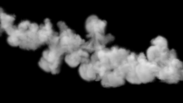
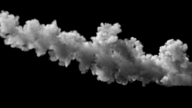
Example: Advection Method Types
|
| Anchor | ||||
|---|---|---|---|---|
|
| Section | ||||||||||||||||||||||||||||||||||
|---|---|---|---|---|---|---|---|---|---|---|---|---|---|---|---|---|---|---|---|---|---|---|---|---|---|---|---|---|---|---|---|---|---|---|
Example: Steps Per Frame (SPF)
|
Active Bodies
| UI Text Box | size | medium|
|---|---|---|
| ||
Interaction between Active Bodies and the Phoenix FD Fire/Smoke Simulator is not supported yet. |

Active Bodies | use_activeBodySolverNode – Enables the simulation of Active Bodies.
Active Body Solver | activeBodySolverNode – Specifies the Active Body Solver node holding the objects to be affected by the Phoenix FD SimulationPhoenix Simulation.
| Anchor | ||||
|---|---|---|---|---|
|
Texture UVW
| UI Text Box | size | medium|
|---|---|---|
| ||
The main purpose of the Texture UVW feature is to provide dynamic UVW coordinates for texture mapping that follow the simulation. If such simulated texture coordinates are not present for mapping, textures assigned to your simulation will appear static, with the simulated content moving through the image. This undesired behavior is often referred to as 'texture swimming'. UVW coordinates are generated by simulating an additional Texture UVW Grid Channel which has to be enabled under the Output roll-out for the settings below to have any effect. The custom UVW texture coordinates can be used for advanced render-time effects, such as recoloring of mixing fluids, modifying the opacity or fire intensity with a naturally moving texture, or natural movement of displacement over fire/smoke and liquid surfaces. Some examples uses are:
The Texture UVW channel values represent the UVW coordinates of each Cell in the Simulator, with a range of [ 0 - 1 ]. The channel is initialized when a simulation is started in one of two ways:
|
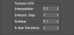
Interpolation | texuvw_interpol_influence – Blends between the UVW coordinates of the liquid particle at time of birth and its UVW coordinates at the current position in the Simulator. When set to 0, no interpolation will be performed - as a consequence, textures assigned to the fluid mesh will be stretched as the simulation progresses. This is best used for simulations of melting objects. When set to 1, the UVW coordinates of the fluid mesh will be updated with a frequency based on the Interpol.Step parameter - this will essentially re-project the UVWs to avoid stretching but cause the textures assigned to the fluid to 'pop' as the re-projection is applied. If you intend to apply e.g. a displacement map to a flowing river, set this parameter to a value between 0.1 and 0.3 - this will suppress both the effects of stretching and popping. See the Interpolation example below.
Interpol. Step | texuvw_interpol_step – Specifies the update frequency for the UVW coordinates. When set to 1, the UVWs are updated on every frame, taking into account the Interpolation parameter. See the Interpolation Step example below.
Antitear | texuvw_antitear_influence – Use this option when the assigned texture appears twisted, torn apart or otherwise distorted. This may happen when the simulation is moving very fast, therefore increase both the Antitear and A-tear Iterations to let Phoenix FD attempt Phoenix attempt to resolve the distortion.
A-tear Iterations | texuvw_antitear_iterations – The number of Antitear iterations performed for every Step of the simulation. Increasing this parameter will help resolve UVW distortion issues by allowing Phoenix FD to run the Antitear operation multiple times. Note that this may slightly increase the time it takes for the simulation to complete.
| Anchor | ||||
|---|---|---|---|---|
|
| Section | |||||||||||||||||||
|---|---|---|---|---|---|---|---|---|---|---|---|---|---|---|---|---|---|---|---|
Example: Interpolation
|
| Anchor | ||||
|---|---|---|---|---|
|
| Section | |||||||||||||||||||
|---|---|---|---|---|---|---|---|---|---|---|---|---|---|---|---|---|---|---|---|
Example: Interpolation Step
|
|