![]()
Page History
Overview
The rendering process in Phoenix FD is separated from the simulation, but for ease of operation is performed by the same object that performs the simulation. However, this is only true for the grid's content, not for the particles contained in the cache file. If you want to render the secondary effect particles (foam, splashes, or drag particles), create a Particle Shader object and add the Simulator to it, so the Particle Shader can use the cache data loaded by the Simulator.
| UI Text Box | ||||
|---|---|---|---|---|
| ||||
If you want to render the particle content of the Simulator (e.g. foam, splashes, or drag particles), create a Particle Shader object and add the simulator to it. You may also check the Volumetric Rendering In-Depth guide for tips on speeding up the rendering of volumetric effects with V-Ray. |
The surface rendering modes of the Phoenix Simulator make it behave just like any regular geometry - 3ds Max materials can be applied to the Simulator.
The liquid surface of a PhoenixFD simulation is generated from the Liquid Particles. The particles are converted into a mesh and shaded by the material assigned to the simulator object. This section contains the controls for this meshing process.
Advanced control over the shading is provided with the Phoenix Grid Texture which can be used to drive the properties of a material applied to a liquid surface.
| UI Text Box | ||||
|---|---|---|---|---|
| ||||
UI Path: ||Select Liquid Simulator | LiquidSim object|| > Modify panel > Rendering rollout |
Actions
Render Presets... – Opens a menu for loading and saving different presets. The following options are available:
| Fancy Bullets | ||
|---|---|---|
| ||
|
Parameters
| Anchor | ||||
|---|---|---|---|---|
|
Mode | rendMode – Specifies the method for visualizing the grid content.
Volumetric – Visualizes the content as a standard 3ds Max atmospheric. This method is used mostly for fire and smoke.
Volumetric Geometry – This method requires V-Ray. Used to export deep images and render elements such as normals, velocity, multi matte, etc. It produces the same result as the Volumetric option by using procedural geometry made up from multiple transparent layers.
| UI Text Box | ||||
|---|---|---|---|---|
| ||||
Approximate and Approximate+Shadows options for the Scattering parameter in the Smoke color window are not supported in Volumetric Geometry mode. For a complete list of the supported Render Elements in both Volumetric and Volumetric Geometry mode, please check the V-Ray Render Elements Support page. |
Volumetric Heat Haze – This method requires V-Ray. It produces the same result as the Volumetric Geometry option, and also adds a heat haze effect when used with the Heat Haze parameter. Note that you might need to increase the Max depth of a VRayMtl with refraction in case it intersects with the Heat Haze shader.
| Anchor | ||||
|---|---|---|---|---|
|
Mesh – The content is converted into a standard 3ds Max mesh using the options in the Mesh Smoothing section. This mode is mostly used for liquids but can be applied to thick smoke using a scatter material or to plumes of smoke to create effects such as large underwater bubbles.
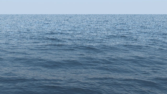
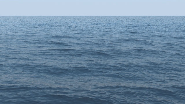
Ocean Mesh – The grid content is extended to a flat area, fitting the camera's view. In most cases, this mode is used with a displacement texture such as the Phoenix FD Ocean Texture.
Cap Mesh – Only the upper liquid surface is rendered. This mode can be used for swimming pools and other placid liquid surfaces.
| Anchor | ||||
|---|---|---|---|---|
|
| UI Text Box | ||||
|---|---|---|---|---|
| ||||
The ocean surface can be generated only when the liquid touches the sides and the bottom of the grid, which act as a container for the liquid. The detail of the mesh extension around the simulator depends on the camera resolution - for each pixel of the viewport or the rendered image, one or several polygons are generated, depending on the Ocean Subdivisions option. |
| Anchor | ||||
|---|---|---|---|---|
|
Invert Cutter | invgizmo – When enabled, rendering will occur only outside of the render cutter. This is not the same as a cutter with inverted geometry because any rays that do not intersect the cutter will be shaded as well.
| UI Text Box | ||||
|---|---|---|---|---|
| ||||
If using a Render Cutter for a liquid pouring into a glass or otherwise contained into another refractive object, you may need to set the Mode to Isosurface. By default, the mode is set to Mesh which may produce artifacts in the rendered image. |
Invert Liquid Volume | solidbelow – By default, grid values above 0.5 are assumed to be liquid, and values below 0.5 are assumed empty. When enabled, the convention switches to the opposite such that values above 0.5 are assumed empty, and values below 0.5 are assumed to be liquid.
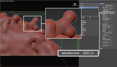
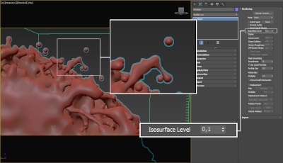
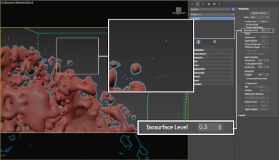
Isosurface Level | surflevel - Allows you to specify a threshold value for the generation of the liquid surface. Grid cells below this value will be ignored. By default, the Isosurface Level is set to 0.5 and should only be modified if there is flickering in the generated geometry. Isosurface Level is used only in Isosurface, Mesh, Ocean Mesh and Cap Mesh Modes.
| UI Text Box | ||||||||||||||||||||||||||||||||||
|---|---|---|---|---|---|---|---|---|---|---|---|---|---|---|---|---|---|---|---|---|---|---|---|---|---|---|---|---|---|---|---|---|---|---|
| ||||||||||||||||||||||||||||||||||
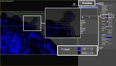
The proper value for the Isosurface Level parameter depends on the numerical range of the surface channel. For example, Phoenix FD liquids are kept in the range of 0 to 1. A value of 0 means there is no liquid in a certain voxel, and a value of 1 means the cell is 100% full of liquid. Values in between indicate a certain mixture of air and liquid. For such cache files, an Isosurface Level value of 0.5 is best for visualizing the surface between the air and liquid. Imported caches from Houdini, on the other hand, use positive and negative values to indicate whether a voxel is inside or outside the liquid volume, so a correct "halfway" Isosurface Level value would be 0.0.
|
Ocean
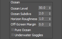
Ocean Level | oceanlevel – Used with the Ocean Mesh and Cap Mesh rendering modes. Specifies the water level as a percentage of the total grid height.
| UI Text Box | ||||
|---|---|---|---|---|
| ||||
|
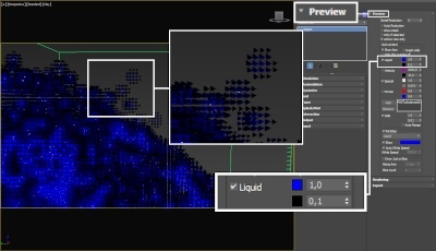
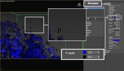
Ocean Subdivs | meshsubdiv – Used with the Ocean Mesh and Cap Mesh rendering modes. When generating the far areas of the surface, this determines how many vertices will be generated for each pixel of the image. Like with V-Ray subdivisions, the square of the parameter value is used. For example, if you increase the subdivisions twice, the vertices count will grow four times. For more information, see the Ocean Subdiv. example below.
| UI Text Box | ||||
|---|---|---|---|---|
| ||||
Increasing the Ocean Subdivs may dramatically increase the amount of consumed RAM. |
Horizon Roughness | oceanhorizrough – Controls the roughness of the distant ocean surface near the horizon. Adds more detail to the waves, which is especially helpful when using a highly reflective material for the ocean surface. Increasing this value can potentially produce visible noise when rendering an animation. To counter this effect, increase the Ocean Subdivs parameter.
Off-Screen Margin (%) | oceanextramargin – The ocean is generated only in the camera view, which can lead to problems when using camera motion blur, using reflections, using refractions with Underwater Goggles enabled, or when the ocean casts shadows on objects underwater. This option allows you to extend the ocean further from the borders of the camera view in order to solve such issues. The value is a percentage of the image size.
Pure Ocean | pureocean – Creates a flat ocean surface up to the Ocean Level height. It does not need loaded caches and if there are any, it ignores their content, so no simulation details will show. Thus changing frames and generating the ocean surface is very quick. This allows you to preview the behavior of the Phoenix FD Ocean Texture when Displacement is enabled or if you want to set up your texture for the Wave force. The option is available for both preview and rendering in Ocean Mesh or Cap Mesh modes. During preview, it requires the Show Mesh option to be enabled in the Preview roll-out.
Underwater Goggles | uwglasses – This option is designed to be used when the camera is placed under the water in Ocean Mesh or Cap Mesh mode. When enabled, a few polygons are added in front of the camera, and the grid content is kept outside of the resulting mesh. The result is similar to real underwater goggles in that the field of view shrinks.
| Anchor | ||||
|---|---|---|---|---|
|
Example: Ocean Subdivs
| Section | ||||||||||||||||||||
|---|---|---|---|---|---|---|---|---|---|---|---|---|---|---|---|---|---|---|---|---|
|
| Anchor | ||||
|---|---|---|---|---|
|
Mesh smooth
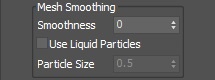
Smoothness | smoothmesh – Specifies the number of smoothing passes. The higher the value, the smoother the result, but the mesh will require more time to calculate. Used when Mode is set to Mesh, Ocean Mesh, or Cap Mesh to reduce the roughness of the mesh.
Use Liquid Particles | useprt – Enables particle-based smoothing of the mesh. It requires Liquid particles to be simulated and exported to the cache files. This method overcomes the limitations of the basic smoothing without particles, which can flicker in animation and cause small formations in the mesh to shrink.
Particle size | prtsz – Used to make the liquid thicker or thinner. Works only when Use Liquid Particles is enabled. This parameter specifies the distance from the mesh surface to the particle centers.
Motion blur
| UI Text Box | ||||
|---|---|---|---|---|
| ||||
To render your simulation with Motion Blur, you need to enable Velocity channel export from the Output roll-out of your simulator. When rendering liquids, the Motion blur of the mesh is obtained by shifting each vertex along the velocity by the shutter time. If rendering a Liquid simulation with secondary particle effects such as Foam, Splashes or Mist, you would also have to enable Velocity export for each particle system under the Output roll-out → Output Particles section. |
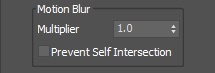
Multiplier | mbmult – Specifies a multiplier that affects the strength of the motion blur. This value can be a negative number.
Prevent Self Intersection | mbself – In certain cases, the shifted vertices might penetrate the opposite side of the geometry. When enabled, this option prevents such situations. The self-intersection analysis is expensive, so enable this parameter only when an intersection is obvious.
| UI Text Box | ||||
|---|---|---|---|---|
| ||||
Phoenix FD meshes are motion blurred in a different way than regular transforming and deforming geometries. When rendering regular meshes with motion blur, the entire mesh is moved along its transformation path back and forward in time, and so each individual vertex of the mesh follows this path. However, for each rendered frame, a new Phoenix mesh must be built from the voxel grid, and so it usually has a different number of vertices than the previous and the next frame. Because of this, individual vertices can not be traced back or forward in time between frames. Instead, motion blur of fluid meshes uses the velocity of vertices which is recorded by the simulation, and moves each vertex back and forward in time along the vertex velocity. This is why the generated liquid mesh does not support frame sub-sampling for motion blur. This may cause a mis-match between the liquid and transforming/deforming objects in your scene that interact with it. The fluid mesh is generated from data at the exact rendered frame and fluid data for the preceding or following frames is not used, unlike regular deforming meshes. As a consequence, the liquid and the objects in your scene would synchronize best if those objects do not use additional geometry samples for motion blur. |
Displacement
| UI Text Box | ||||
|---|---|---|---|---|
| ||||
Displacement is a technique intended to add detail to the simulation during the rendering. The idea of the Phoenix displacement is similar to the usual geometry displacement: a texture is sampled, and the corresponding point of the fluid volume or surface is shifted in a direction at a distance determined by the texture. You can plug any V-Ray, 3ds Max or Phoenix texture maps. |
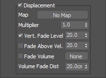
Displacement | displacement – Enables the displacement effect.
| Anchor | ||||
|---|---|---|---|---|
|
Multiplier | displmul – Specifies the displacement amount.
Vertical Fade Level | fadebylevel, displfade – How high above the Ocean Level the displacement will stop having effect. This option is needed for ocean simulations where you have liquid flying or splashing high above the ocean surface, so that the ocean displacement will affect only the calm ocean surface, but will not displace the liquid flying high above the ocean, or you would be able to see small pieces of liquid move up and down as they fly due to the ocean waves displacement. Above the Vertical Fade Level there will be no displacement at all, and below it the displacement will be strongest near the Ocean Level and will gradually be reduced moving up from the ocean surface. This parameter is a percentage of the grid height, just as the Ocean Level option.
Fade Above Velocity | fadebyvel, displvelfade – If the fluid velocity (in voxels/sec) in a voxel is higher than this value, there will be no displacement at all. When the velocity is lower than this value, the higher the velocity, the weaker the displacement will be. This allows you to suppress displacement for the fast moving parts of the fluid where the displacement would visibly disturb the motion in an unnatural manner, and thus you can have only the still ocean surface displaced with waves. This option requires the Grid Velocity channel to be exported to the simulation cache files from the Output rollout.
| UI Text Box | ||||
|---|---|---|---|---|
| ||||
The Fade Volume feature can be used when the liquid is in contact with a geometry surface such as a shore or a ship and the displacement breaks the contact by moving the liquid mesh away from, or into the geometry. |
Fade Volume | usefadeobj, fadeobj – There will be no displacement inside this geometry object, and outside it the displacement will be gradually reduced at a distance specified by the Volume Fadeout Distance parameter. This is useful if you have a geometry such as a sea vessel moving in high displaced waves, or a static geometry such as a beach into which the fluid is splashing. In these cases, you can use these geometries as fade volumes and use small Fadeout Distance around them, so the displaced liquid mesh and the objects would match precisely - otherwise the displacement may pull away the liquid from such geometries or force the liquid to penetrate them.
Volume Fadeout Distance | displgeomfade – Specifies the distance in world units around the object where the displacement will fade out going near the object.
| Viewtracker | ||||
|---|---|---|---|---|
|