Versions Compared

Key

  • This line was added.
  • This line was removed.
  • Formatting was changed.

This page provides information on the V-Ray Omni Light, also known as a Point Light.


Overview

...

The V-Ray Omni Light or Point Light is a V-Ray specific light source that can be used to create a physically accurate light. It emits light from a single location in all directions. 


UI Path: ||obj Network|| > V-RayV-Ray Omni Light


Emission

...

Section
Column
width55%

Enabled – Turns the light on and off.

Intensity – Multiplier for the light strength; this is also the light intensity in the units set by the Units parameter. For illustration, see the Intensity example below. 

Units – Specifies the light units. Using correct units is essential when using the V-Ray Physical Camera. The light automatically takes the scene's unit scale into consideration to produce the correct result for the scale you are working with. The possible values are:

Default – The color and multiplier directly determine the visible color of the light without any conversion. The light surface appears with the given color in the final image when seen directly by the camera (assuming there is no color mapping involved).
Lumens – Total emitted visible light power measured in lumens. When this setting is used, the intensity of the light does not depend on its size. A typical 100W electric bulb emits about 1500 lumens of light.
Lm/m/m/sr – Visible light surface power measured in lumens per square meter per steradian. When this setting is used, the intensity of the light depends on its size.
Watts – Total emitted visible light power measured in watts. When this setting, the intensity of the light does not depend on its size. Keep in mind that this is not the same as the electric power consumed by a light bulb for example. A typical 100W light bulb only emits between 2 and 3 watts as visible light.
W/m/m/sr – Visible light surface power measured in watts per square meter per steradian. When this setting is used, the intensity of the light depends on its size.

Color – Specifies the color of the Omni Light.

Decay – Controls the behavior of the light intensity in relation to the distance of the light source.

Illumination Mask – Specifies which objects to be affected by the V-Ray Omni Light.

LPE Tag – Allows you to specify a string tag that can be used in a Light Path Expression to isolate the contribution from this light. See the Advanced Light Path Expressions page for more information.

Column
width5%


Column
width40%


Anchor
intensity
intensity

...

...


Example: Intensity

...


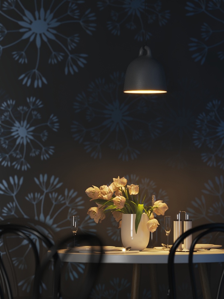
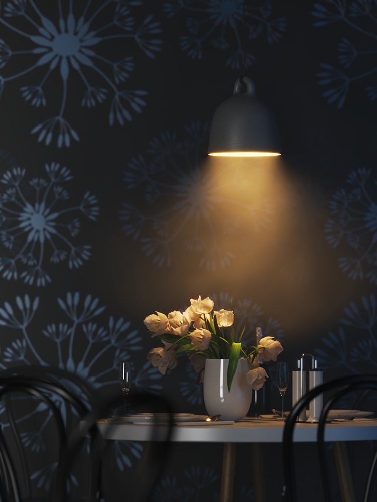
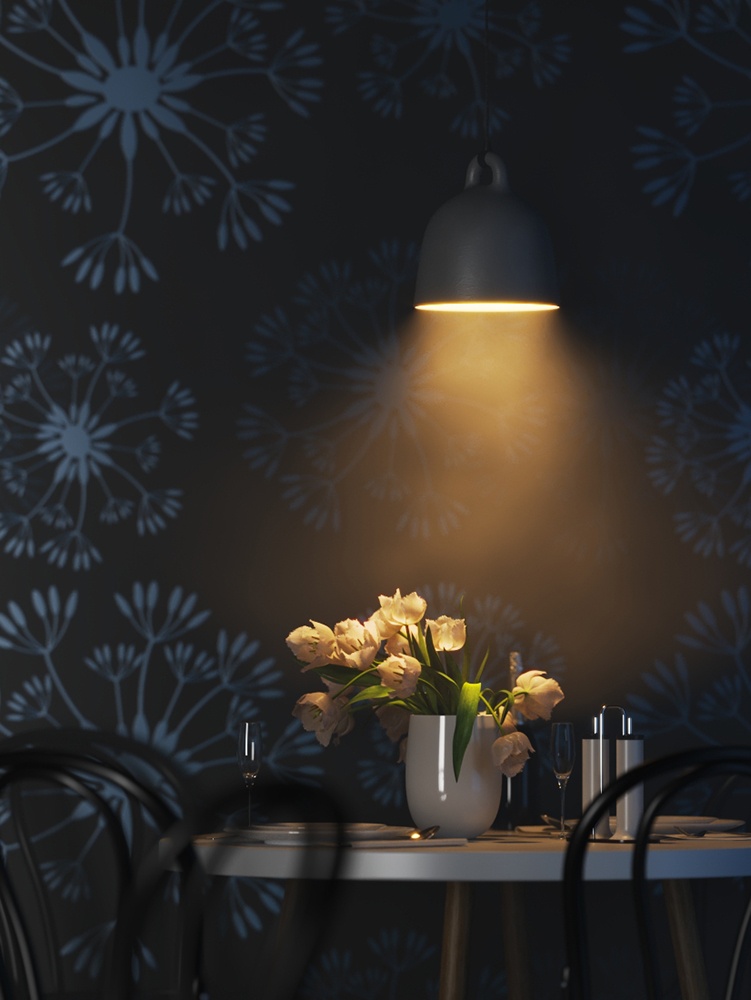
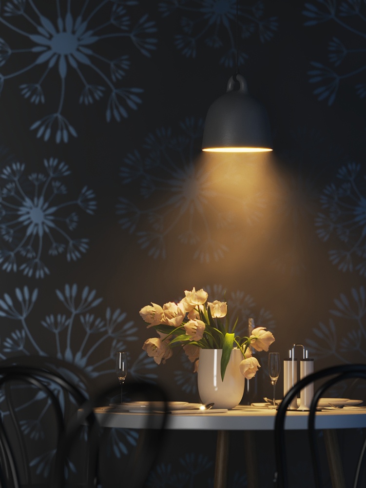
This example shows how changing the Intensity parameter changes the light in the scene. Note that the values are calculated as Lumens

Section
 
Column
width20%


Column
width60%
Image slider
minLabel1000
maxLabel7500
Panel
borderStylenone

Intensity = 1000 Lumens

Panel
borderStylenone

Intensity = 2500 Lumens

Panel
borderStylenone

Intensity = 5000 Lumens

Panel
borderStylenone

Intensity = 7500

Column
width20%


Shadows

...

Section
Column
width55%

Enabled – When enabled, the light casts shadows. Disable this option to turn off shadows for the light.

Color – Controls the color of shadows for this light. Note that anything different from black is not physically correct.

Radius – Specifies the size of the light. A value of 0.0 makes the light a point light. Larger values produce soft (area) shadows. For illustration, see the Shadow Radius example below.

Bias – Moves the shadow toward or away from the shadow-casting object (or objects). Higher values move the shadow toward the object(s) while lower values move it away. If this value is too extreme, shadows can "leak" through places they shouldn't or "detach" from an object. Other effects from extreme values include moire patterns, out-of-place dark areas on surfaces, and shadows not appearing at all in the rendering.

Shadow Mask – Specifies objects that cast shadows when light is directed at them.

Column
width5%


Column
width40%


...

Anchor
radius
radius

Example: Shadow Radius

...


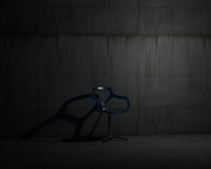
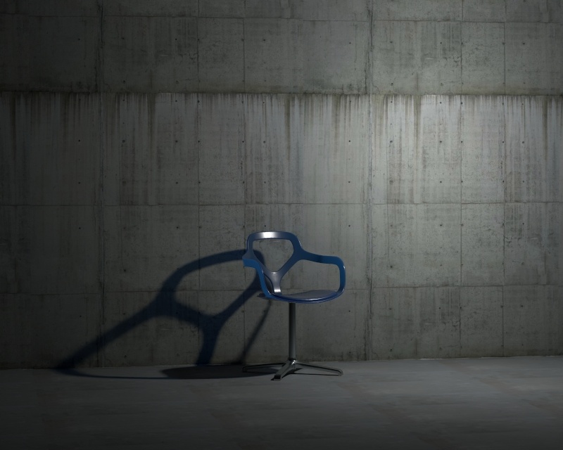
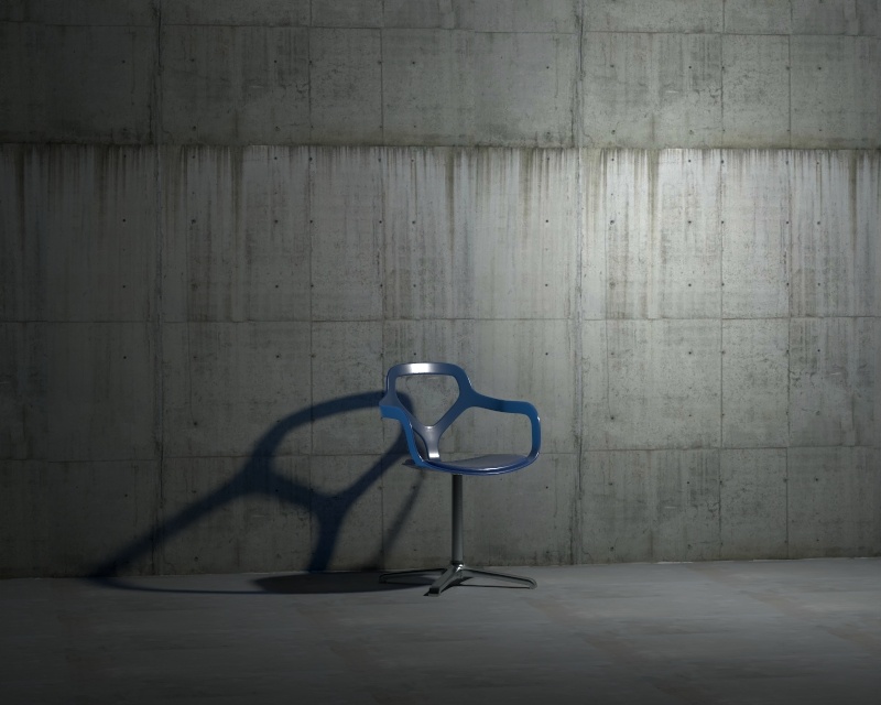
This example shows how the shadow Radius parameter affects the light in the scene. Notice how lesser values result in sharper shadows and greater values result in blurrier and elongated shadows.

Section
 
Column
width20%


Column
width60%
Image slider
Panel
borderStylenone

Radius = 0.0

Panel
borderStylenone

Radius = 0.4

Panel
borderStylenone

Radius = 1.0

Column
width20%


Textures

...

Section
Column
width55%

Emission Color – Specifies the color of the light rays and of the light source itself when visible in renderings.

Shadow Color – Specifies the color of the shadows produced by the light. 

Column
width5%


Column
width40%

...


Decay

...

The Decay parameters determine how the light fades in and out. The Near Decay determines how light fades in. The light isn't at its maximum value at its source, but instead gradually increases until it reaches the Near End. The Far Decay determines how light fades out. The light isn't at its maximum value at its end, but instead gradually decreases after the Far Start.

Decay option is useful for creating hotspots or controlling the length of a "God Rays" effect created with Environment Fog. 


Section
Column
width55%

Near Decay – Toggles near decay on and off. See the examples below for more information.

Near Start – Determines where the fade in starts. Anything before this point is rendered dark.

Near End – Determines where the fade in ends. After this threshold, the light is at its full value.

Far Decay – Toggles far decay on and off. See the examples below for more information.

Far Start – Determines where the fade off starts.

Far End – Determines where the light reaches a value of 0, i.e. completely fades off.

Column
width5%


Column
width40%


Advanced

...

Section
Column
width55%

Affect Diffuse – Determines whether the light affects the diffuse properties of the materials.

Affect Specular – Determines whether the light affects the specular of the materials. This means glossy reflections.

Affect Atmospherics – Determines whether the light influences the atmospheric effects in the scene.

Diffuse Contribution – When Affect Diffuse is enabled, specifies a multiplier for the effect of the light on the diffuse component.

Specular Contribution – When Affect Specular is enabled, specifies a multiplier for the effect of the light on the specular component.

Atmospheric Contribution – When Affect Atmospherics is enabled, this value determines the amount of involvement.

Motion Blur Samples – Specifies the number of samples used to sample the light for motion blur.

Caustics Multiplier – Specifies a multiplier for the generated caustics by the selected object. Note that this multiplier is cumulative - it does not override the multiplier in the Caustics Tab of the V-Ray Render Settings.

Caustics Subdivs – Only used when calculating Caustics. Lower values mean more noisy results, but render faster. Higher values produce smoother results but take more time.

Cut-off Threshold – Specifies a threshold for the light intensity, below which the light is not computed. This can be useful in scenes with many lights, where you want to limit the effect of the lights to some distance around them. Larger values cut away more of the light; lower values make the light range larger. When this value is 0.0, the light is calculated for all surfaces.

Store With Irradiance Map – When enabled and GI calculation is set to Irradiance map, V-Ray calculates the effects of the V-Ray Omni Light and stores them in the irradiance map. The result is that the irradiance map is computed more slowly but the rendering takes less time. The irradiance map can also be saved for later use.

Column
width5%


Column
width40%


...


Anchor
near
near

Multiexcerpt
MultiExcerptNameDecay
Section
Column
width5%

...


Column
width35%

Example: Decay Near Start

This example shows the variances achieved by changing the Near Start parameters only.

Image slider
Panel
borderStylenone

Image Modified

Near Start 10, Near End 60

Panel
borderStylenone

Image Modified

Near Start 30, Near End 60

Panel
borderStylenone

Image Modified

Near Start 50, Near End 60

Column
width10%

...


Column
width35%

Example: Decay Near End

This example shows the variances achieved by changing the Near End parameters only.

Image slider
Panel
borderStylenone

Image Modified

Near Start 0, Near End 10

Panel
borderStylenone

Image Modified

Near Start 0, Near End 30

Panel
borderStylenone

Image Modified

Near Start 0, Near End 50

Column
width5%

...


Anchor
far
far

Section
Column
width5%

...


Column
width35%

Example: Decay Far Start

This example shows the variances achieved by changing the Far Start parameters only.

Image slider
Panel
borderStylenone

Image Modified

Far Start 10, Far End 60

Panel
borderStylenone

Image Modified

Far Start 30, Far End 60

Panel
borderStylenone

Image Modified

Far Start 50, Far End 60

Column
width10%

...


Column
width35%

Example: Decay Far End

This example shows the variances achieved by changing the Far End parameters only.

Image slider
Panel
borderStylenone

Image Modified

Far Start 60, Far End 60

Panel
borderStylenone

Image Modified

Far Start 60, Far End 100

Panel
borderStylenone

Image Modified

Far Start 60, Far End 120

Column
width5%

...


...


Section
Column
width35%

...


Column
width35%

Example: Near and Far Decay

This example shows some artistic lighting results achieved by using both Near and Far decay options.

Image slider
Panel
borderStylenone

Image Modified

Near Start 0, Near End 15, Far Start 30, Far End 60

Panel
borderStylenone

Image Modified

Near Start 20, Near End 35, Far Start 40, Far End 55

Panel
borderStylenone

Image Modified

Near Start 30, Near End 60, Far Start 90, Far End 120

Column
width30%

...


...