This page provides some details in the settings available when using the VRScan Material in V-Ray.
Overview
The VRScan material allows the rendering of scanned BRDF material data stored in .vrscan files. These files are produced by Chaos Group's own internal material scanner and accompanying material creator software.
With V-Ray 6, the Scanned Material doesn't require a separate from Chaos license to work correctly.
In earlier V-Ray versions, the Scanned Material requires a separate render license to work correctly. Without a license, the material renders with a watermark.
The scanned material renders the captured appearance of an actual physical material sample, that has been scanned with special scanner hardware. The material goes beyond single-point BRDF capture and can faithfully represent the textured appearance of a large number of real-world surfaces using bidirectional texture function (BTF) approximation.
Because the scanned material simply reproduces the way a physical material responds to light, is has no notion of "diffuse" or "reflection" components, "normal" or "bump" maps.
Currently, the material can render only opaque surfaces. Also, for the moment except for some general tint control, the material is unmodifiable - i.e. you can't change glossiness, increase reflectivity etc. You can only change the overall tint of the material. In its present form, the material is targeted at users that need to match exactly a given real-world sample.
The .vrscan files tend to be quite large as they need to pack a lot of data (they need to describe the BRDF of the material over its entire surface).
For more details on VRscans, please see the Chaos Scans documentation space for information on downloadable sample scenes and Frequently Asked Questions or visit the Chaos Scans website.

UI Paths
||V-Ray Asset Editor|| > Materials (right-click) > VRScan
||V-Ray Asset Editor|| > Create Asset (left-click) > Materials > VRScan
UI Options
From the Add Attribute button, you can select additional attributes. For more information on attributes, see the Attributes section.
The context options of the Color Slot allow to Copy and Paste a color from one color slot to another, as well as to reset the color selection.
A Reset option is provided in the context menu of each Number Slider. You can reset the slider value to the default one.

Parameters
File – The file name with the data for the scanned material; usually has a .vrscan extension.
Tiling Factor – Global multiplier for U and V coordinates.
Plain Material – A strategy used for material display. It controls the visibility of textures (if present). Possible values are:
Average BRDF – Averages the BRDF and removes any anistropy. This mode can be used on objects without proper UV coordinates.
Average isotropic BRDF – Averages the BRDF and can be used to speed up the rendering for previews. Because texture details are removed, this also removes any tiling artifacts that might arise if the scanned sample does not tile very well. UV coordinates are still needed because most BRDFs are slightly anisotrpic.

Advanced Options
Two Sided – Forces the back-facing polygons to be shaded in the same way as the front-facing ones. When this option is disabled, the back-facing polygons appear black.
Transparency – Disables transparency for materials that store such information. this can be useful for speeding up the rendering, especially when the transparency produces little or no effect.
Trace Depth – Controls the number of reflection bounces. A value of -1 means that the reflection bounces are controlled by the global V-Ray trace depth in the Global switches rollout of the Renderer Settings.
Cutoff – A threshold used to speed up reflections. If the contribution of reflections falls below this threshold, the reflections are not traced. This is similar to the Cutoff threshold of the V-Ray Generic material.

Information
The section displays some useful information contained in the .vrscan file, like the actual material sample size.

Appearance
The Appearance parameters allow for further customization of the scanned material.
Filter – Enables the use of the color filter.
Filter Color – A color multiplier for the material sample and can be used to tint the material (it affects the color of the reflections as well as a post effect).
Filter Strength – Multiplies the effect of the filter.
Paint – Enables the use of Paint Color.
Paint Color – Changes the color of the material without loosing the texture or change the reflection color. For example, changing the color of wood or leather without losing their textures.
Paint Strength – Multiplies the effect of the paint.
Gamma – Adjusts the gamma of the material (including paint color and filter color if used) as a post effect.
Saturation – Controls the saturation of the material (including paint color and filter color if used) as a post effect.

Clear Coat
The clear coat parameters are similar to those found in the VRay Car Paint Material. These parameters are only available if while scanning an object, it is determined that the object possesses the properties of a material with a clear coat.
Reflection – Enables the tracing of a clear coat layer for the material's reflection.
Specular – Enables highlights from point light sources for the coat layer.
IOR – Determines the Index of Refraction of the coat layer and controls the strength of the reflections. A value of 1.0 does not produce any reflections and disables the coat layer. Higher values produce stronger clear coat reflections. The .vrscan file contains the correct value (typically 1.6) for this parameter, which is set automatically when the file is loaded but can be adjusted higher or lower if needed.
Bump Strength – The coat layer has a built-in bump map stored into the material sample file. This parameter allows control over the strength of that bump.
![]()
Type – Controls how the texture is positioned on the geometry. 2D (UV Channel) – The texture uses the object UV coordinates. UV Channel/Set – Specifies the index of the mapping channel data to use. A value of 1 takes the first available channel. Repeat U/V – Determines how many times the texture is repeated in the 0 to 1 UV square. Lock U/V Repeat – Locks the U/V Repeat. Offset U/V – Controls the texture offset in the U and V direction. Rotate – Rotates the texture (in degrees). Tile U/V – Tiles the texture in the U and V direction. If the option is disabled, the Default texture color is used outside the 0 to 1 UV square. Default color is found in Parameters > Color Manipulation. Mirror U/V – Mirrors the texture in the U and V direction separately. The option cuts the texture in the half flipping one side vertically or horizontally. This can be used to avoid seams in-between non-tileable repeated textures. 2D (UV Channel) Random Offset – Randomizes the texture offset. When rendering many instances using the same material, with this option enabled, you get a variation of the look. Random Rotate – Randomizes the material rotation from one object to another. When rendering many instances using the same material, with this option enabled, you get a variation of the look. Tri-Planar ProjectionTexture Placement
Tri-Planar Projection – The texture will be automatically projected onto the object (along the X, Y, and Z object space axis). This works similarly to the Tri-Planar texture. Use the Tiling Factor parameter to change the projected texture size.2D (UV Channel)

Tri-Planar Projection

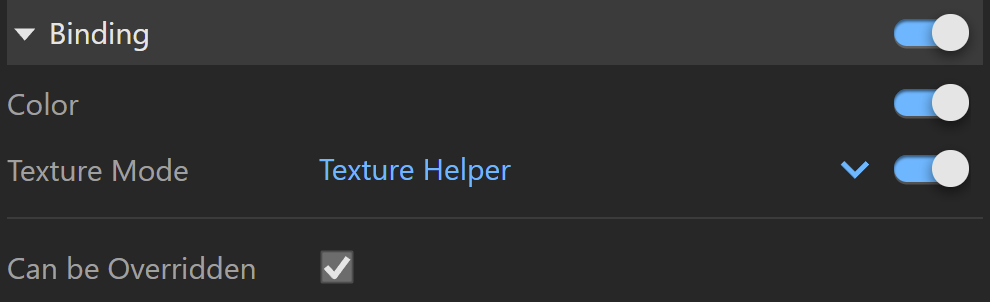
Binding
Binding – Enables connection/binding between V-Ray and the corresponding base application material.
Color – Enables color binding. Changing the V-Ray material color changes the corresponding base application material color and vice versa.
Texture Mode – Enables texture binding. Changing the V-Ray material texture changes the corresponding base application material texture and vice versa.
Auto – By default binds the Diffuse texture to the base app material.
Texture Helper – Allows the use of a helper texture as a base application material map. The same helper is used if the binded texture is a procedural map. This is useful if every time you have to set texture placement for a map that can't be displayed accurately in the base app.
Custom – Allows the use of a custom texture as base application material map. Disabling this parameter allows changing the base app material texture without affecting the V-Ray material.
Bake – In this mode complex texture networks are baked to a single image used as a viewport preview. Differences between the rendered result and the viewport preview may occur due to the fact that only the texture confined within the 0 to 1 UV square is baked. This affects most procedural patterns and textures with custom UV placement configuration. Raytraced and Tri-planar textures are not supported.
It is recommended to save all raw bitmap buffers (textures embedded in SketchUp like SketchUp library materials textures) to disk before activating the Bake mode to preserve them.
Texture – Selected textures are displayed in the viewport. Keep in mind that procedural textures are not displayed. Note that the viewport texture will not affect the way the material is rendered in V-Ray. It is mainly used for preview purposes.
Override Control
Can be Overridden – When enabled, the material can be overridden by the Material Override option in the Settings.
Attributes
The attributes from the following expandable menus are available for the VRscan material.
Raytrace Properties
Visible to Camera – When enabled, makes objects using this material visible to the camera.
Visible to Reflections – When enabled, this option makes objects using this material visible for the Reflection rays.
Visible to Refractions – When enabled, this option makes objects using this material visible for the Refraction rays.
Cast Shadows – When disabled, all objects with this material applied do not cast shadows.

Material ID
ID Number – Isolates objects as an R/G/B mask in the MultiMatte render elements.
ID Color – Allows you to specify a color to represent this material in the Material ID VFB render element.
Each material is assigned with an automatically generated ID Color.
