Overview
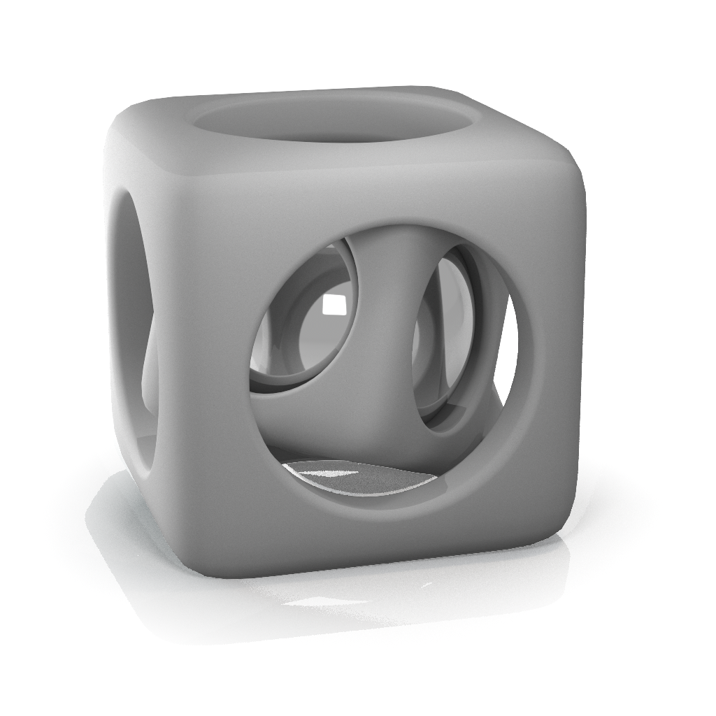
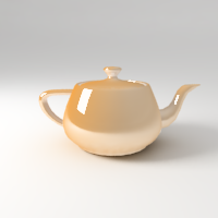
The VRayMtl is a very versatile material that allows for better physically correct illumination (energy distribution) in the scene, faster rendering, and more convenient reflection and refraction parameters. This material can be easily set up to simulate a wide variety of surfaces such as plastics, metals, glass and more by adjusting a handful of parameters.
Furthermore, with the VRayMtl you can apply different texture maps, control the reflections and refractions, add bump and displacement maps, force direct GI calculations, and choose the BRDF to determine how light interacts with the surface material.
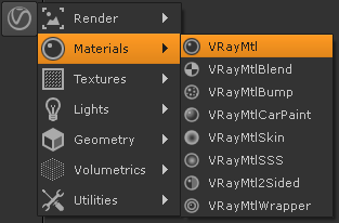
UI Path: ||Toolbar|| > V-Ray menu icon > Materials > VRayMtl
Inputs
The following parameters can be mapped with textures. To enable the input in the Node Graph, enable the tickbox next to the corresponding slider in the Properties pane.
Diffuse
Roughness
Opacity
Self-Illumination
Reflection Color
Reflect Glossiness
Anisotropy
Refraction Color
Refraction Glossiness
Translucency Color
Main Parameters Tab
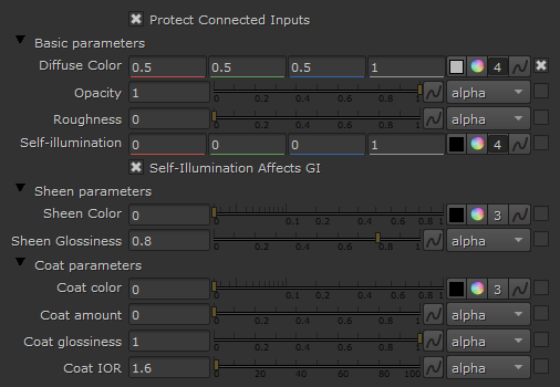
Diffuse Color – The diffuse color of the material. Note: the actual diffuse color of the surface also depends on the reflection and refraction colors.
Opacity – Allows the user to assign opacity to the material where white is completely opaque and black is completely transparent. This way you can create a material that has a non-uniform opacity.
Roughness – Used to simulate rough surfaces or surfaces covered with dust (for example, skin, or the surface of the Moon).
Self-Illumination – Controls the emission of the surface.
Self-Illumination Affects GI – When enabled, the self-illumination affects global illumination rays and allows the surface to cast light on nearby objects. Note: It may be more efficient to use area lights for this effect.
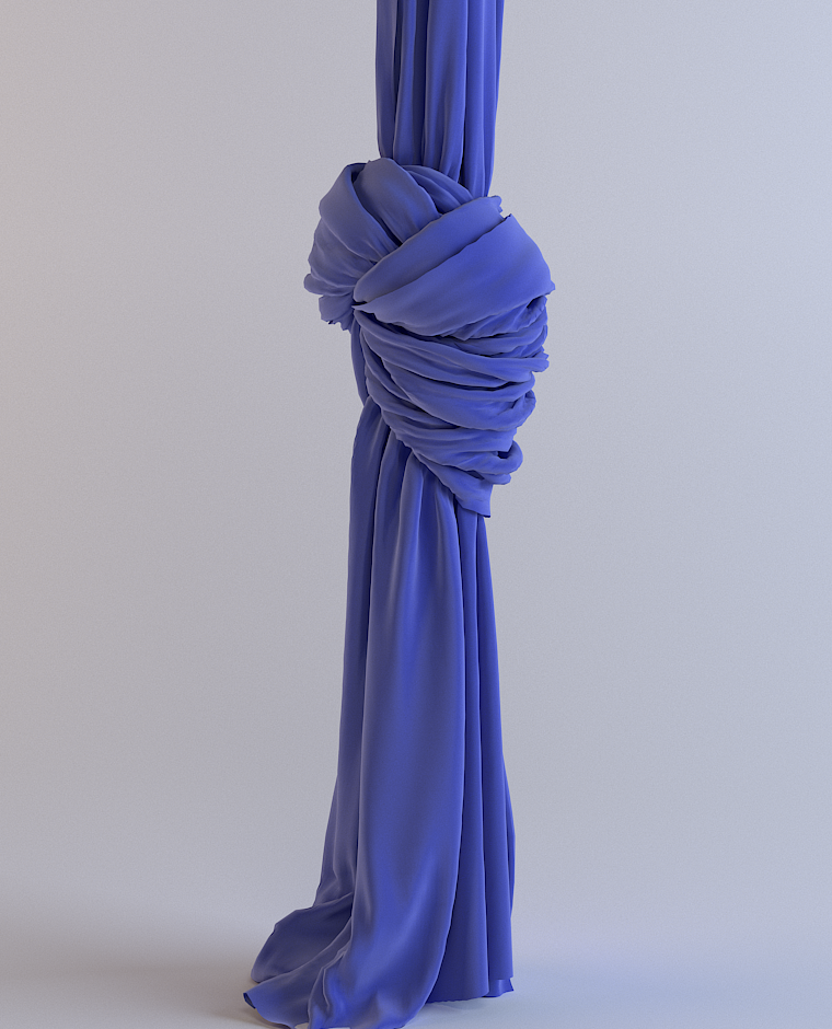
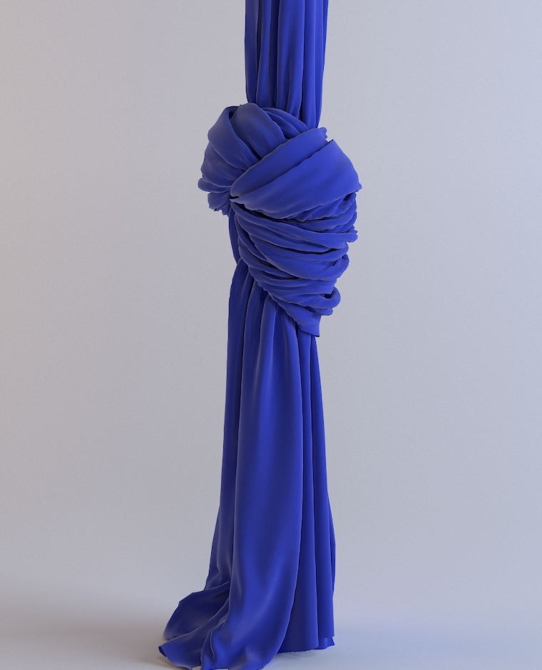
The Sheen layer can be used for creation of cloth material, such as satin.
Sheen Color – Specifies the color.
Sheen Glossiness – Controls the sharpness of reflections. A value of 1.0 means all of the light reaches the diffuse color, and when the value is smaller, the cloth material looks glossier. See the Sheen Glossiness parameter below for more information.
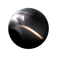
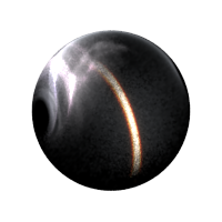
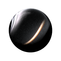
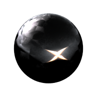
Example: Sheen Glossiness
This example shows how changing the glossiness parameter of the sheen layer affects the material. A smaller value makes the sheen layer reflect most of the light. Increasing the value allows more light to reach the diffuse component.
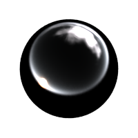
Glossiness = 0.1

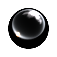
Glossiness = 0.3

Glossiness = 0.6
Glossiness = 0.8

Glossiness = 0.9
Coat Color – Determines the coat layer's color. A texture map can be used here.
Coat amount – Specifies the blending weight of the coat layer. A value of 0 does not add a coat layer, while higher values blend the coat gradually. See the Coat Amount example below for more information.
Coat glossiness – Controls the sharpness of reflection. A value of 1.0 means perfect glass-like reflection; lower values produce blurry or glossy reflections. See the Coat Glossiness example below for more information.
IOR – Specifies the Index of Refraction for the coat layer.
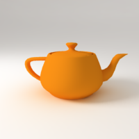
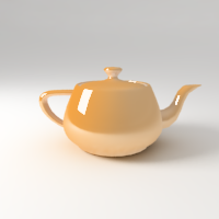
Example: Coat Amount
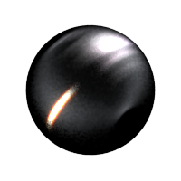
This example shows how the Amount value affects the look of the material. The base Reflection Glossiness is 0.76 and the Coat glossiness is set to 0.985. IOR is 2.2 and the Coat Color is the default white.
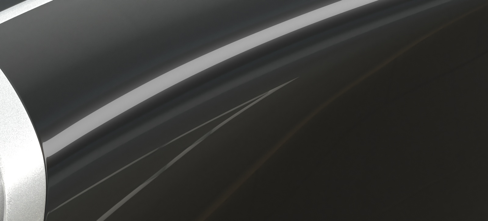
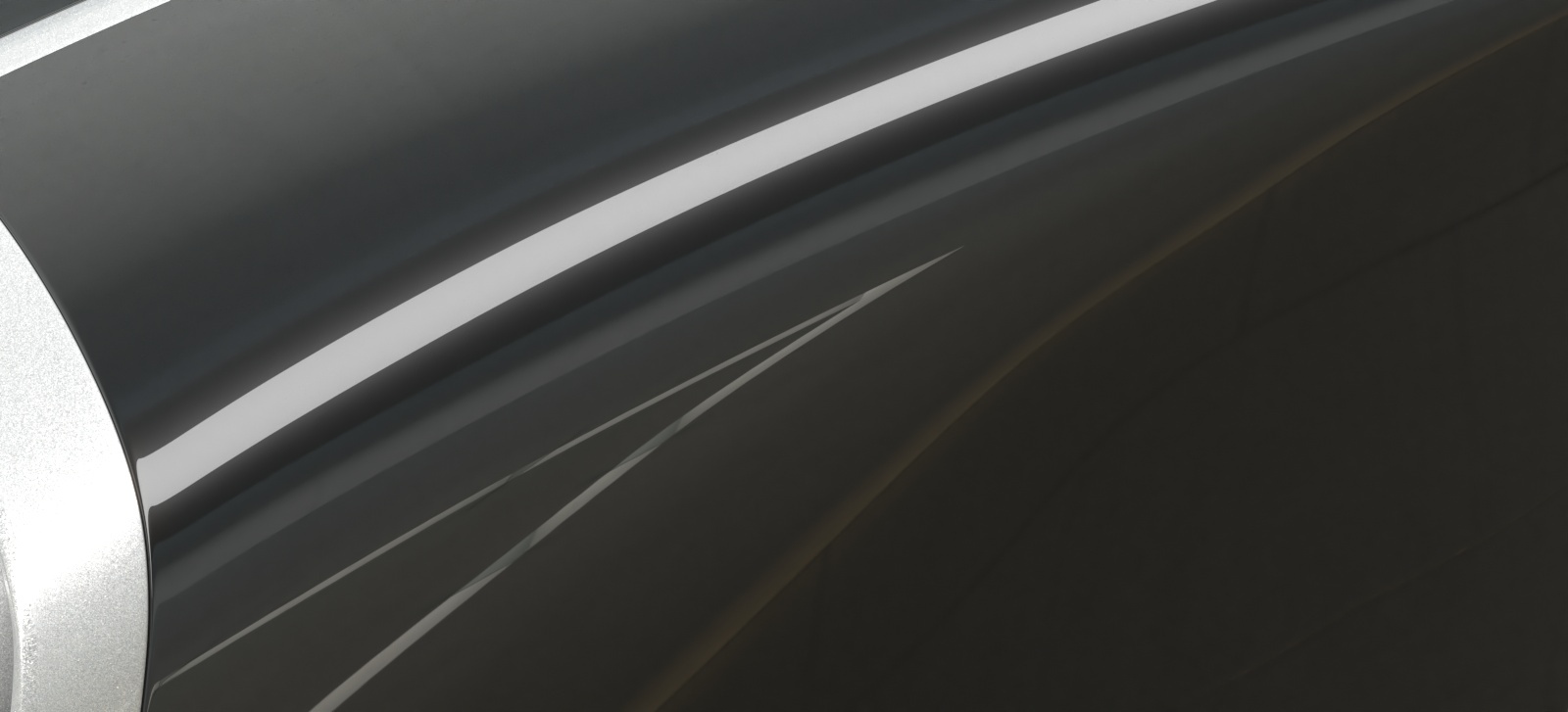
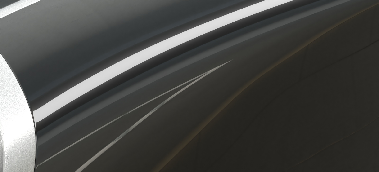
Example: Coat Glossiness
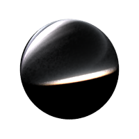
Coat glossiness controls the sharpness of the coat reflection. In this example, the base Reflection Glossiness is set to 0.76 and the Coat Amount is set to 1. IOR is 2.2 and the Coat Color is the default white. Notice how higher values produce glossier reflection and lower values make it look blurry.

Coat amount = 0

Coat amount = 0.1
Coat amount = 0.3
Coat amount = 0.5
Coat amount = 0.7

Coat amount = 1.0

Coat Clossiness = 0.2

Coat Glossiness = 0.4

Coat Glossiness = 0.6

Coat Glossiness = 0.8
Coat Glossiness = 1.0
Options Rollout
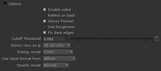
Double sided – When enabled, V-Ray will flip the normals for back-facing surfaces with this material assigned. Otherwise, the lighting on the "outer" side of the material will be computed always. You can use this to achieve a fake translucent effect for thin objects like paper.
Reflect on back – When disabled, V-Ray will calculate reflections for the front side of objects only. Checking it will make V-Ray calculate the reflections for the back sides of objects too.
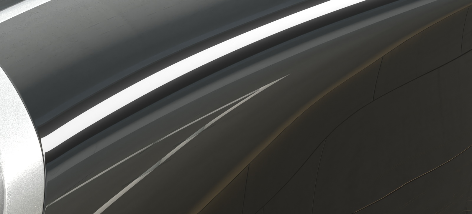
Glossy Fresnel – When enabled, uses glossy Fresnel to interpolate glossy reflections and refractions. It takes the Fresnel equation into account for each "microfacet" of the glossy reflections, rather than just the angle between the viewing ray and the surface normal. The most apparent effect is less brightening of the grazing edges as the glossiness is decreased. With the regular Fresnel, objects with low glossiness may appear to be unnaturally bright and "glowing" at the edges. The glossy Fresnel calculations make this effect more natural.
Use Roughness – When enabled, highlights/reflections will be determined by the material's Roughness, otherwise highlights/reflections will be determined by the material glossiness.
Fix dark edges – Enabling will fix dark edges that sometimes appear on objects with glossy materials.
Cutoff Threshold – This is a threshold below which reflections/refractions will not be traced. V-Ray tries to estimate the contribution of reflections/refractions to the image, and if it is below this threshold, these effects are not computed. Do not set this to 0.0 as it may cause excessively long render times in some cases.
Glossy rays as GI – Specifies on what occasions glossy rays will be treated as GI rays:
Never – Glossy rays are never treated as GI rays.
GI rays only – Glossy rays will be treated as GI rays only when GI is being evaluated. This can speed up rendering of scenes with glossy reflections and is the default.
Always – Glossy rays are always treated as GI rays. A side effect is that the Secondary GI engine will be used for glossy rays. For example, if the primary engine is irradiance map, and the secondary is light cache, the glossy rays will use the light cache (which is a lot faster).
Energy mode – Determines how the diffuse, reflection, and refraction color affect each other. V-Ray tries to keep the total amount of light reflected off a surface to be less than or equal to the light falling on the surface (as this happens in the real life). For this purpose, the following rule is applied: the reflection level dims the diffuse and refraction levels (a pure white reflection will remove any diffuse and refraction effects), and the refraction level dims the diffuse level (a pure white refraction color will remove any diffuse effects). This parameter determines whether the dimming happens separately for the RGB components or is based on the intensity:
Color – Causes dimming to be performed separately on the RGB components. For example, a pure white diffuse color and pure red reflection color will give a surface with cyan diffuse color (because the red component is already taken by the reflection).
Monochrome – Causes dimming to be performed based on the intensity of the diffuse/reflection/refraction levels.
Use input format from – Sets the material aspect ratio based on the input format of a connected texture file. This only affects 2D Card nodes that have image aspect enabled.
Opacity mode – Controls how opacity is sampled. For more information, see the Opacity mode parameter example below.
Normal – (Legacy) The opacity map is evaluated as normal: the surface lighting is computed and the ray is continued for the transparent effect. The opacity texture is filtered as normal.
Clip – (Very fast) The opacity texture is not filtered and it is clipped to either fully opaque or fully transparent based on the mid-point value. Useful when there are many transparent surfaces one behind the other like leaves.
Stochastic – (Optimal) The opacity texture is filtered and the surface is randomly shaded as either fully opaque or fully transparent for a correct average appearance.
Example: Opacity mode parameter
Opacity mode = Normal
Because the opacity texture is filtered the result is nice and smooth but very slow.

Opacity mode = Stochastic
The texture is still filtered, so the result is smooth but render times are greatly improved.
Opacity mode = Clip
The texture is forced to black or white; the render time is very fast, but the result is sharper which may increase flickering in animation.
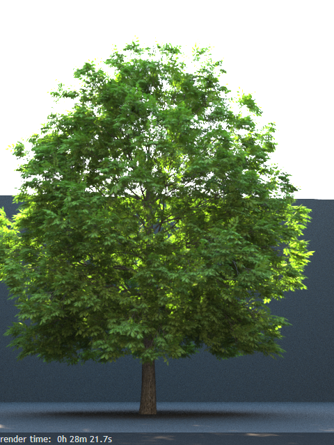
The renders below show a blow-up of the tree to better show the effect of the different modes. Note that in the first two renders the opacity is blurry because of the texture filtering.
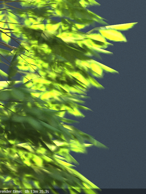
Opacity mode = Normal
Because the texture is filtered, this makes the normal-sized render smoother and reduces flickering in animation, but the render time is very slow.
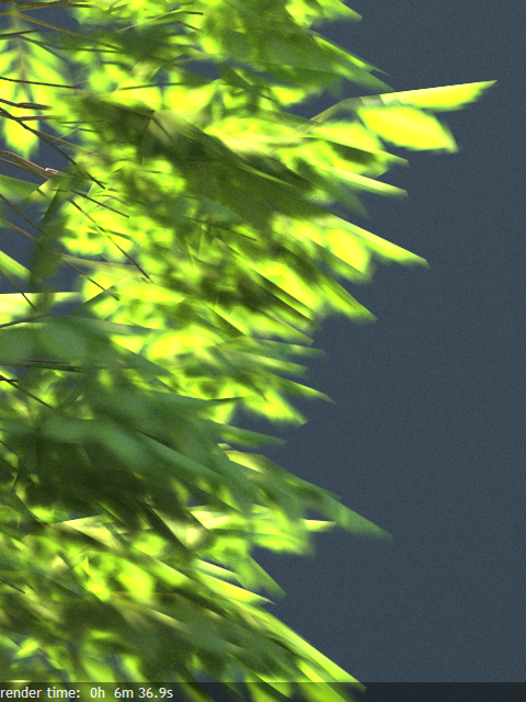
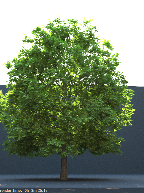
Opacity mode = Stochastic
The texture is still filtered, which keeps the normal-sized render smooth, and the render time is much better.
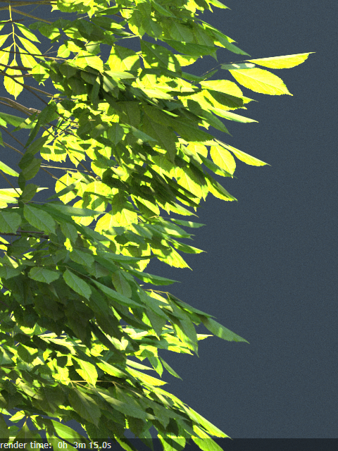
Opacity Mode = Clip
Because the opacity map is forced to either full black or white, the result is sharp. The render time is very good, but the increased sharpness can increase flickering in animations.
Reflection Parameters Tab
The BRDF parameter determines the type of the highlights and glossy reflections for the material. This parameter has an effect only if the reflection color is different from black and reflection glossiness is different from 1.0.
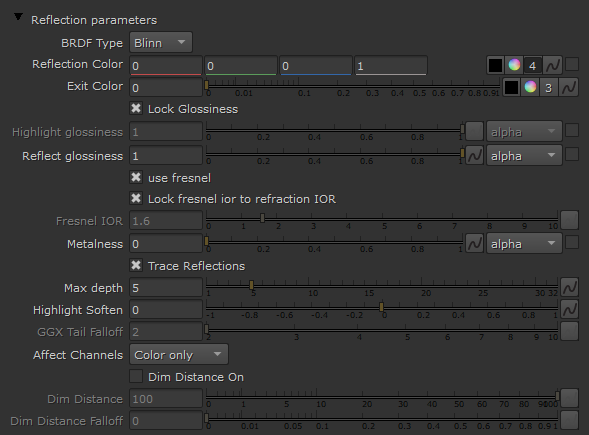
BRDF Type – Determines the type of BRDF (the shape of the highlight). For more information, see The BRDF Type example below.
Phong – Phong highlight/reflections.
Blinn – Blinn highlight/reflections.
Ward – Ward highlight/reflections.
GGX – GGX highlight/reflections.
GGX is the most modern and flexible BRDF(Bidirectional reflectance distribution function) type and is able to better represent a broad range of materials thanks to its ability to control the shape of the specular lobe.
There currently isn't any particular performance difference between models and there is little reason to choose any of the other types.
Reflection Color – Specifies the reflection color. Note that the reflection color dims the diffuse surface color. For more information, see The Reflection Color Parameter example below.
Exit Color – If a ray has reached its maximum reflection depth, this color will be returned without tracing the ray further.
Lock Glossiness – When disabled, you can enter different values for the highlight glossiness and Reflection glossiness. However, this will not produce physically correct results.
Highlight glossiness – Determines the shape of the highlight on the material. Normally this parameter is locked to the Reflection glossiness value in order to produce physically accurate results.
Reflect glossiness – Controls the sharpness of reflections. A value of 1.0 means perfect mirror-like reflection; lower values produce blurry or glossy reflections. For more information, see The Reflection Glossiness Parameter example below.
use fresnel – Enabling makes the reflection strength dependent on the viewing angle of the surface. Some materials in nature (glass etc) reflect light in this manner. Note that the Fresnel effect depends on the index of refraction as well. For more information, see The Use Fresnel Option example below.
Lock Fresnel IOR To Refraction IOR – Allows you to unlock the Fresnel IOR parameter for finer control over the reflections.
Fresnel IOR – The IOR to use when calculating Fresnel reflections. Normally this is locked to the Refraction IOR parameter, but you can unlock it for finer control.
Metalness – Controls the reflection model of the material from dielectric (metalness 0.0) to metallic (metalness 1.0). Note that intermediate values between 0.0 and 1.0 do not correspond to any physical material. This parameter can be used with PBR setups coming from other applications. The reflection color should typically be set to white for real world materials.
Trace Reflections – Check to enable reflections for the material.
Max depth – The number of times a ray can be reflected. Scenes with lots of reflective and refractive surfaces may require higher values to look correct.
Highlight soften – Soften the edge of the BRDF at light/shadow transitions.
GGX Tail Falloff – Only available when the BRDF is set to GGX. It allows us to fine tune the specular reflections by controlling the rate at which the sharp specular highlight fades out. Higher values create a highlight with sharper fade out. Lower values spread out the fade out of the highlight. Please note that this parameter does not affect the size of the actual highlight - this is controlled by the Reflect glossiness parameter.
Affect Channels – Allows you to specify which channels are going to be affected by the reflectivity of the material.
Color Only – The reflectivity will affect only the RGB channel of the final render.
Color+alpha – This will cause the material to transmit the alpha of the reflected objects, instead of displaying an opaque alpha.
All channels – All channels and render elements will be affected by the reflectivity of the material.
Dim distance On – Enables the Dim distance parameter which allows you to stop tracing reflection rays after a certain distance.
Dim distance – Specifies a distance after which the reflection rays will not be traced.
Dim distance falloff – A fall off radius for the dim distance.
Example: The BRDF Type
This example demonstrates the differences between the BRDFs available in V-Ray. Note the different highlights produced by the different BRDFs.

BRDF type is Phong
BRDF type is Blinn
BRDF type is Ward
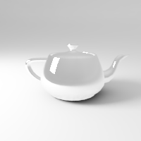
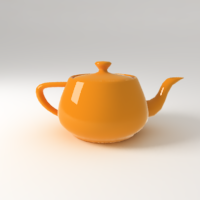
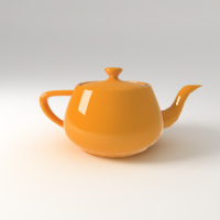
Example: The Reflection Color Parameter
This example demonstrates how the Reflection color parameter controls the reflectivity of the material. Note that this color also acts as a filter for the diffuse color (e.g. stronger reflections dim the diffuse component).
Reflection color is black (0, 0, 0)
Reflection color is medium gray (128, 128, 128)
Reflection color is white (255, 255, 255)
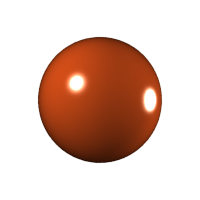
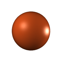
Example: The Reflection Glossiness Parameter
This example demonstrates how the Reflection glossiness and highlight glossiness parameters control the highlights and reflection blurriness of the material. The Reflection Color is white and the Use Fresnel box is checked.
Reflection/highlight Glossiness is 1.0
(perfect mirror reflections)

Reflection/highlight glossiness is 0.8
Reflection/highlight glossiness is 0.6
Example: The Use Fresnel Option
This example demonstrates the effect of the Use Fresnel option. Note how the strength of the reflection varies with the IOR of the material. For this example, the Reflection color is pure white (255, 255, 255).

Fresnel is off

Fresnel is on, IOR is 1.3
Fresnel is on, IOR is 2.0
Fresnel is on, IOR is 10.0
Anisotropy Rollout
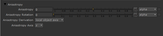
Anisotropy – Determines the shape of the highlight. A value of 0.0 means isotropic highlights. Negative and positive values simulate "brushed" surfaces. For more details, please see The Anisotropy Parameter example below.
Rotation – Determines the orientation of the anisotropic effect in a float value between 0 and 1 (where 0 is 0 degrees and 1 is 360 degrees).
Anisotropy Derivation – Specifies the method to use for deriving anisotropy axes.
local object axis – Uses the Anisotropy Axis parameter to determine Anisotropy Derivation.
uvw generator – Generates Anisotropy Derivation based on UVW.
Anisotropy Axis – Choose the local object axis to use when anisotropy_derivation is set to local object axis.
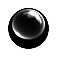
Example: The Anisotropy Parameter
This example demonstrates the effect of the Anisotropy parameter. Note how the different values stretch the reflections horizontally or vertically.
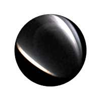
Anisotropy is -0.9
Anisotropy is -0.45
Anisotropy is 0.0 (no anisotropy)
Anisotropy is 0.45
Anisotropy is 0.9
Example: The Anisotropy Rotation Parameter
This example demonstrates the effect of the Anisotropy rotation parameter. For all the images in this example, the Anisotropy parameter itself is -0.95.
Anisotropy rotation is 0 (0.0 degrees)
Anisotropy rotation is 0.125 (45.0 degrees)
Anisotropy rotation is 0.25 (90.0 degrees)
Anisotropy rotation is 0.375 (135.0 degrees)
Bitmapped Anisotropy rotation
Refraction Parameters Tab
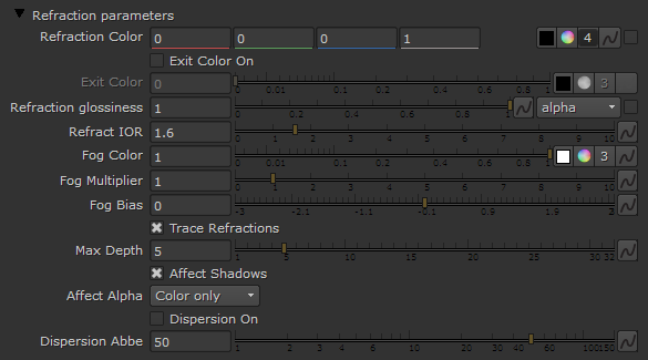
Refraction Color – Refraction color. Note that the actual refraction color depends on the reflection color as well. For more information, see The Refraction Color Parameter example below.
Exit Color On – If this is on, and a ray has reached the maximum refraction depth, the ray will be terminated and the Refraction Exit Color value returned. When this is off, the ray will not be refracted but will be continued without changes.
Exit Color – If a ray has reached its maximum depth this color will be returned instead of tracing the ray further.
Refraction glossiness – Controls the sharpness of refractions. A value of 1.0 means perfect glass-like refraction; lower values produce blurry or glossy refractions. For more information, see The Refraction Glossiness Parameter example below.
Refract IOR – Index of refraction for the material, which describes the way light bends when crossing the material surface. A value of 1.0 means the light will not change direction. For more information, see The Refraction IOR Parameter example below.
Fog Color – The attenuation of light as it passes through the material. This option helps simulate the fact that thick objects look less transparent than thin objects. Note that the effect of the fog color depends on the absolute size of the objects and is therefore scene-dependent. For more information, see The Fog Color Parameter example below.
Fog Multiplier – The strength of the fog effect. Smaller values reduce the effect of the fog, making the material more transparent. Larger values increase the fog effect, making the material more opaque. For more information, see the Fog Color Parameter example below.
Fog Bias – Changes the way the fog color is applied. Negative values make the thin parts of the objects more transparent and the thicker parts more opaque and vice-versa (positive numbers make thinner parts more opaque and thicker parts more transparent).
Trace Refractions – Check to enable refractions for the current material.
Max Depth – The number of times a ray can be refracted. Scenes with lots of refractive and reflective surfaces may require higher values to look correct.
Affect Shadows – Causes the material to cast transparent shadows to create a simple caustic effect dependent on the refraction color and the fog color. For accurate caustic calculations, disable this parameter and instead enable Caustics in the GI rollout of the VrayRenderer node. Simultaneous usage of both Caustics and Affects Shadows can be used for artistic purposes but will not produce a physically correct result.
Affect Alpha – Allows you to specify which channels are going to be affected by the transparency of the material.
Color Only – The transparency will affect only the RGB channel of the final render.
Color+alpha – This will cause the material to transmit the alpha of the refracted objects, instead of displaying an opaque alpha. Note that currently, this works only with clear (non-glossy) refractions.
All channels – All channels and render elements will be affected by the transparency of the material.
Dispersion On – Enables the calculation of true light wavelength dispersion.
Dispersion Abbe – Allows you to increase or decrease the dispersion effect. Lowering it widens the dispersion and vice versa.
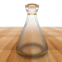
Example: The Refraction Color Parameter
This example demonstrates the effect of the Refraction color parameter to produce glass materials. For the images in this example, the material is with a gray Diffuse color, white Reflection color and Fresnel option on.
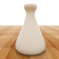
Refraction color is black (0, 0, 0) (no refraction)
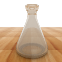
Refraction color is light gray (192, 192, 192)

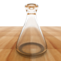
Refraction color is white (255, 255, 255)
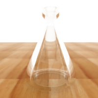
Example: The Refraction Glossiness Parameter
This example demonstrates the effect of the Refraction glossiness parameter. Note how lower Refraction glossiness values blur the refractions and cause the material to appear as frosted glass.

Refraction glossiness is 1.0
Refraction glossiness is 0.9
Refraction glossiness is 0.8
Example: The Refraction IOR Parameter
This example demonstrates the effect of the Refraction IOR parameter. Note how light bends more as the IOR deviates from 1.0. The case when the index of refraction (IOR) is 1.0 produces a transparent object. Note, however, that in the case of transparent objects, it might be better to assign an opacity map to the material, rather than use refraction.
Refraction IOR is 0.8
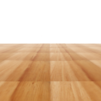
Refraction IOR is 1.0

Refraction IOR is 1.3

Refraction IOR is 1.8
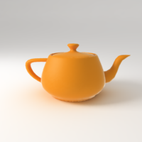
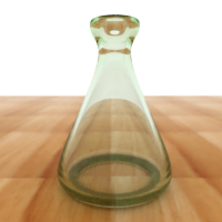
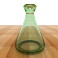
Example: The Fog Color Parameter
This example demonstrates the effect of the Fog color parameter. Notice how the thick areas of the object are darker in the two images on the right because of the light absorption of the fog.

Fog color is white (255, 255, 255) (no light absorption)

Fog color is gray (128, 128, 128)
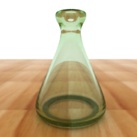
Fog color is green (116, 190, 102)
Example: The Fog Multiplier Parameter
This example demonstrates the effect of the Fog multiplier parameter. Smaller values cause less light absorption because of the fog; while higher values increase the absorption effect.
Fog multiplier is 0.5

Fog multiplier is 1.0
Fog multiplier is 1.5
Subsurface scattering Rollout
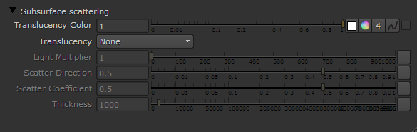
Translucency Color – Normally the color of the sub-surface scattering effect depends on the Fog color; this parameter allows you to additionally tint the SSS effect.
Translucency – Selects the algorithm for calculating translucency (also called sub-surface scattering). Note that refraction must be enabled for this effect to be visible. Currently, only single-bounce scattering is supported. The possible values are:
None – No translucency is calculated for the material;
Hard (wax) model – This model is specifically suited for hard materials like marble;
Soft (water) model – This model is mostly for compatibility with older V-Ray versions (1.09.x);
Hybrid model – This is the most realistic sss model and is suitable for simulating skin, milk, fruit juice and other translucent materials.
Light Multiplier – A multiplier for the translucent effect.
Scatter Direction – Controls the direction of scattering for a ray. 0.0 means a ray can only go forward (away from the surface, inside the object); 0.5 means that a ray has an equal chance of going forward or backward; 1.0 means a ray will be scattered backward (towards the surface, to the outside of the object).
Scatter Coefficient – The amount of scattering inside the object. 0.0 means rays will be scattered in all directions; 1.0 means a ray cannot change its direction inside the sub-surface volume.
Thickness – Limits the rays that will be traced below the surface. This is useful if you do not want or do not need to trace the whole sub-surface volume.