This page provides information about the V-Ray Scanned Material in Cinema 4D.
Overview
The Scanned Material allows the rendering of scanned BRDF material data stored in .vrscan files. These files are produced by Chaos' own internal material scanner and accompanying material creator software.
With V-Ray 6, the Scanned Material doesn't require a separate from Chaos license to work correctly.
In earlier V-Ray versions, the Scanned Material requires a separate render license to work correctly. Without a license, the material renders with a watermark.
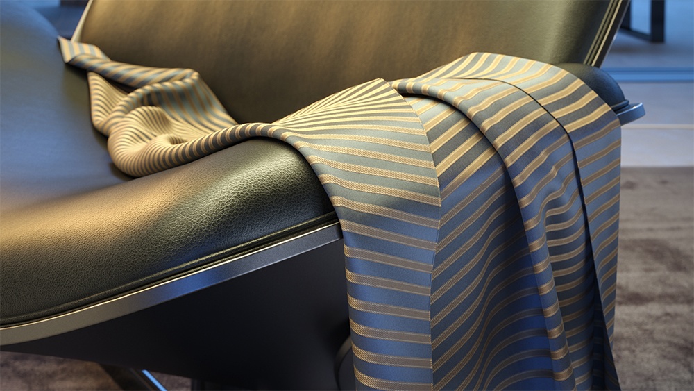
The scanned material renders the captured appearance of an actual physical material sample, that has been scanned with special scanner hardware. The material goes beyond single-point BRDF capture and can accurately represent the textured appearance of a large number of real-world surfaces, using bidirectional texture function (BTF) approximation.
Because the scanned material simply reproduces the way a physical material responds to light, is has no notion of "diffuse" or "reflection" components, "normal" or "bump" maps.
The .vrscan files tend to be quite large as they need to pack a lot of data (they need to describe the BRDF of the material over its entire surface).
For more details on VRscans, please see the Chaos Scans documentation space for information on downloadable sample scenes and Frequently Asked Questions or visit the Chaos Scans website.
UI Paths
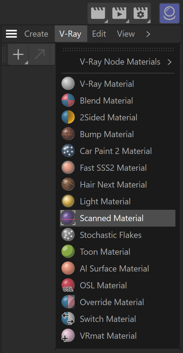
||V-Ray|| > Scanned Material
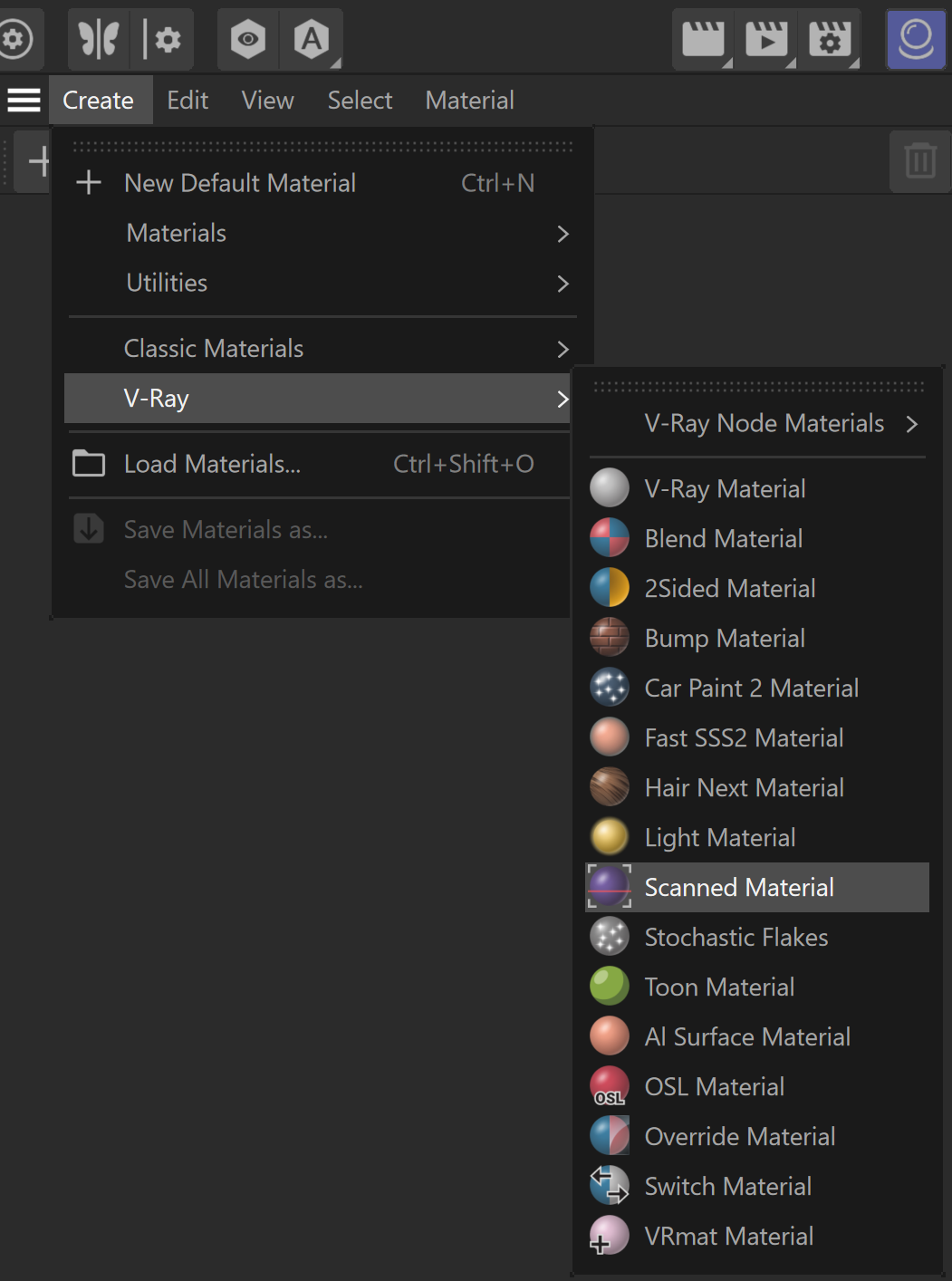
||Create|| > V-Ray > Scanned Material (disabled Separate menu for V-Ray materials)
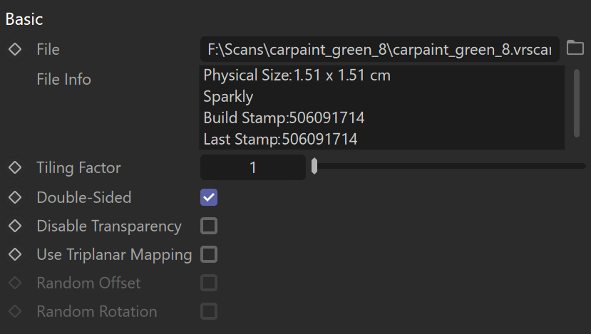
Basic
File – The file name with the data for the scanned material; files have a .vrscan extension.
File Info – Displays info about the loaded .vrscan file.
Tiling Factor – Global multiplier for U and V coordinates.
Double-Sided – Enables both sides of the material.
Disable Transparency – Turns off transparent properties of the material.
Use Triplanar Mapping – Ignores the object's default UV mapping and assigns one with U and V axes parallel to the nearest object-space axes.
Random Offset – Randomizes the material offset when Triplanar Mapping is used.
Random Rotation – Randomizes the material rotation when Triplanar Mapping is used.
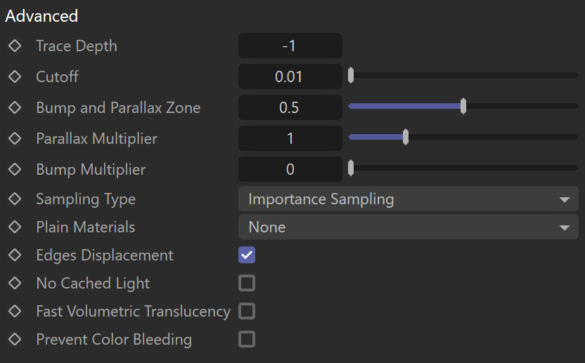
Advanced
Trace Depth – Controls the number of reflection bounces. A value of -1 means that the reflection bounces are controlled by the global V-Ray trace depth in the Global switches rollout of the Renderer Settings.
Cutoff – A threshold used to speed up reflections. If the contribution of reflections falls below this threshold, the reflections are not traced. This is similar to the Cutoff of the V-Ray Material.
Bump and Parallax Zone – Determines the point where additional bump and parallax no longer exist and only natural height effects remain. This option is especially useful in side views of the material, where it might appear flat or less detailed. A value of 0 adds no additional bump and parallax. Value of 1 adds additional bump and parallax equally, regardless of the view angle. All scanned materials by default have the most suitable value loaded for this parameter to achieve the most realistic look. If you need full control over the bump and the parallax, set the value to 1 and work with the Parallax and Bump Multipliers.
Parallax Multiplier – A multiplier for additional parallax and edge displacement strength.
Bump Multiplier – A multiplier for the additional bump.
Sampling Type – Determines which samples are taken around pixels involved in "blurry" effects such as anti-aliasing, depth of field, indirect illumination, area lights, glossy reflections/refractions, translucency, motion blur, etc.
Importance Sampling – Bases the number of samples allocated to a value on the importance of certain aspects, depending on the case. For instance, distance from the camera, if objects are too far, or if more samples are needed to render a realistic result.
Uniform sampling – The number of samples is evenly taken over the entire image.
Plain Materials – A strategy used for material display. It controls the visibility of textures, if any are present. Possible values are:
None – The full material evaluation is always used. The object must have valid UV coordinates.
Average BRDF – Averages the BRDF and can be used to speed up the rendering for previews. Because texture details are removed, this also removes any tiling artifacts that might arise if the scanned sample does not tile very well. UV coordinates are still needed because most BRDFs are slightly anisotropic.
Average Symmetric BRDF – Smooth representation of the material with no maps visible.
Scramble –
Edges Displacement – Uses a special technique that makes the edges of the geometry appear slightly jagged inwards. This option is useful when rendering close-ups of materials with bumps. It is faster than actual displacement and helps to achieve better realism.
No Cached Light – Allows you to disable the cached light for the material, ensuring physical accuracy without the need to switch off GI of the entire scene. Disabling this option results in faster, but less physically accurate render.
Fast Volumetric Translucency – Relevant only to volumetric translucent V-Ray scanned materials. When this option is enabled, the calculation of the volumetric translucency is fast, but less accurate.
Prevent Color Bleeding – When enabled, the indirect GI/glossy rays see the material as gray, thus preventing coloring of the near objects.
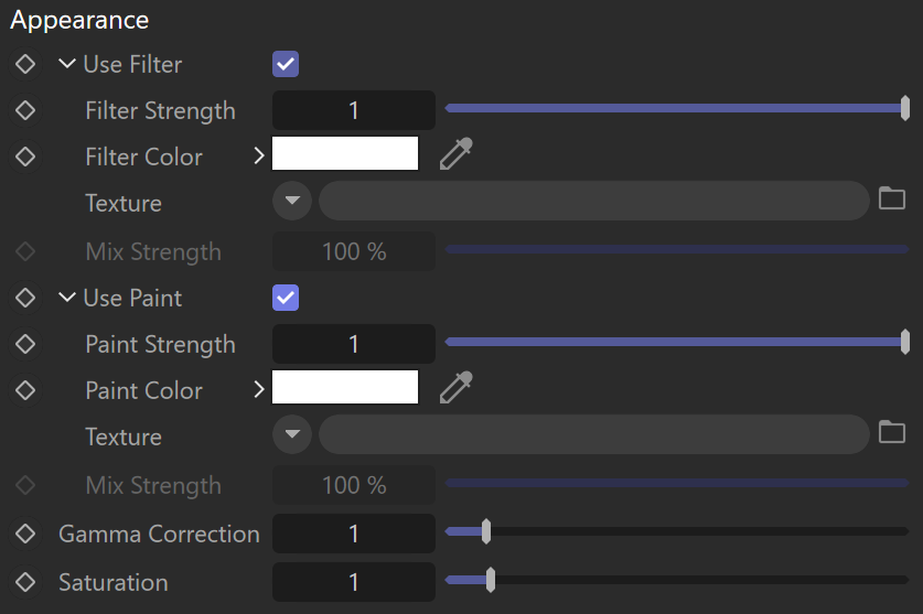
Appearance
Filter Strength – Multiplies the effect of the filter.
Filter Color – A color multiplier for the material sample that can be used to tint the material. Keep in mind that it affects the color of the reflections as well as the post effects. A Texture can also be applied and blended with the color, using the Mix Strength option.
Use Paint – Enables the use of Paint Color.
Paint Strength – Multiplies the effect of the paint.
Paint Color – Changes the color of the material without loosing the texture or changing the reflection color. For example, changing the color of wood or leather without losing their textures.
Gamma Correction – Adjusts the gamma of the material (including paint color and filter color, if used) as a post effect.
Saturation – Controls the saturation of the material (including paint color and filter color, if used) as a post effect.
Clear Coat
Enable – Enables the tracing of a clear coat layer for the material.
Highlights – Enables highlights from point light sources for the coat layer.
Strength – Specifies the strength of the coat reflections.
IOR – Determines the Index of Refraction of the coat layer and controls the strength of the reflections. A value of 1.0 does not produce any reflections and disables the coat layer. Higher values produce stronger clear coat reflections. The .vrscan file contains the correct value (typically 1.6) for this parameter, which is set automatically when the file is loaded but can be adjusted higher or lower if needed.
Bump multiplier – The coat layer has a built-in bump map stored in the material sample file. This allows you to control the strength of that bump.
Coloring – Turns the coat reflections colored.
![]()
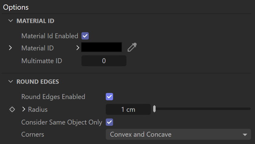
Options
Material ID – The color used by the Material ID render element. You can also use a shader here.
Multimatte ID – The integer ID of the material to be used by the Multi Matte render element.
Round Edges Enabled – Enables the round edges effect which uses bump mapping to smooth out the edges of the geometry during render time.
Radius – Specify a radius (in world units) for the round edges effect. Since the actual geometry is not being changed and only the normals of the faces are affected, large values here may produce undesirable effects.
Consider Same Object Only – When enabled, the rounded corners are produced only along edges that belong to the same object which has the attribute applied. When disabled, rounded corners are produced along edges formed when the object with the attribute intersects other objects in the scene.
Corners – Choose which edges are considered in the calculation. Possible options are:
Covex and Concave – Considers all edges.
Convex Only – Only applies Round Edges effect to edges with convex angles.
Concave Only – Only applies Round Edges effect to edges with concave angles.
Notes
Scanned Material can make use of some of the Render Elements. Here is a list of those elements:
- Clear coat reflections stored in Reflection Render Element;
- Direct Light Contribution stored in Lighting Render Element;
- Indirect lighting by spawned rays stored in Global Illumination (GI) Render Element;
- Material Opacity stored in Alpha Render Element;
- Received caustics stored in Caustics Render Element;
- Diffuse in the Bump and Normal Render Elements.